1
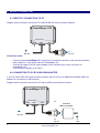
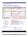
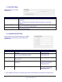
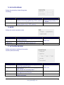
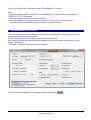
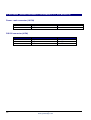
GuardMagic VF1-VF2 programming tool – manual 0.01
GuardMagic VF1-VF2
Programming Tool
(GM2.037)
User Manual
2013
01-05-2013
Table of contents:
1.
2.
1.1
1.2
1.3
3.
4.
5.
5.1.
5.2.
5.3.
5.4.
6.
6.1.
6.2.
7.
7.1.
7.2.
7.3.
7.4.
7.5.
7.6.
7.7.
7.8.
8.
9.
10.
2
INTRODUCTION........................................................................................................... 3
PACKAGES .................................................................................................................. 3
STANDARD PACKAGE ................................................................................................ 3
OPTIONAL (order in additional) .................................................................................... 3
PACKAGE..................................................................................................................... 3
OVERWIEV OF MAIN COMPONENTS ........................................................................ 4
SYSTEM REQUIREMENTS.......................................................................................... 4
NECESSARY INFORMATION FOR MODULE PROGRAMMING................................ 5
NECESSERY INFORMATION FROM YOUR LOCAL GSM PROVIDER...................... 5
NECESSERY INFORMATION FROM YOUR MONITORING STATION....................... 5
NECESSERY INFORMATION TO YOUR MONITORING STATION ............................ 5
ADDITIONAL NAME ..................................................................................................... 5
MODULE CONNECTION.............................................................................................. 6
DIRECTLY CONNECTION TO PC................................................................................ 6
CONNECTION TO PC BY USB-COM ADAPTER......................................................... 6
PROGRAM OVERVIEW .............................................................................................. 7
START THE PROGRAM............................................................................................... 7
UNIT DATA ................................................................................................................... 7
UNIT SETTINGS ........................................................................................................... 8
CONNECTION SETTING.............................................................................................. 8
DATA RECORDING...................................................................................................... 9
MODE ........................................................................................................................... 9
ACTIVATED RECORD.................................................................................................. 9
CONTROL BUTTONS................................................................................................. 10
STARTING OPERATION WITH SOFTWARE
10
PROGRAMMING PROCEDURE ................................................................................ 11
APPENDIX (WIRING DIAGRAM OF GUARDMAGIC VF1, VF2 MODULES) ............ 12
GuardMagic
www.guardmagic.com
1. INTRODUCTION
"GuardMagic VF1-VF2 programming tool” is the special technological complete set and
intended for customer programming and change the setting of GuardMagic VF1 and
GuardMagic VF2 modules by Personal Computer.
In additional "GuardMagic DLLS-DLLE programming tool” utility allows to carry out fuel
tank calibration procedure.
Fuel tank calibration procedure is carried by Personal Computer (Notebook).
2. PACKAGES
1.1
STANDARD PACKAGE
•
•
•
•
1.2
AC/DC (220V/12V) power adapter with cable
Connection cable: VF module – PC (GM4.013)
“GuardMagic VF1-VF2 programming tool” User Guide
CD disk with manuals and software (GM9.211-102)
- 1 pc.
- 1 pc
-1 book
-1 CD
OPTIONAL (order in additional)
• USB-Com adapter
(for connection VF1, VF2 modules to USB port in PC)
1.3
PACKAGE
The complete set is packed into a box from a corrugated cardboard
GuardMagic
www.guardmagic.com
3
3. OVERWIEV OF MAIN COMPONENTS
Connection cable VF1-VF2
modules – PC (GM4.013)
(for connection to: GuardMagic VF1
and VF2 modules to PC by RS-232
communication interface
CD disk
with manuals and software
GM4.013
AC/DC (220V/12V) power adapter
with cable
CD disk contents:
• VF1-VF2 programming software;
• “GuardMagic VF1-VF2 programming tool” User
Manual
4. SYSTEM REQUIREMENTS
System requirements to the PC:
- MS Windows XP, MS Windows Vista, MS Windows 7;
- Intel Pentium IV 600 or above (or AMD analogue);
- Main memory 256MB or above;
- 10 free space on a hard disk;
- Mouse and keyboard;
- RS-232 port (or USB port*);
- Video adapter and color monitor with the resolution not less than 800 x 600;
- CD or DVD ROM.
Note:
If your PC has only USB interface in additional will be need to use standard USB-Com
adapter.
4
GuardMagic
www.guardmagic.com
5. NECESSARY INFORMATION FOR MODULE PROGRAMMING
5.1. NECESSERY INFORMATION FROM YOUR LOCAL GSM PROVIDER
Before carrying out of the module programming, it is necessary to get information from your
GSM operator:
parameters of GPRS at yours GSM the provider, namely:
- access point name/APN - APN server of yours GSM provider;
- name (Login)* – user name for access to a server of yours GSM the provider;
- password* – password for access to the server of yours GSM the provider;
* - often GSM provider has not (and don’t give) Name and Password to access to its GPRS
server.
This information will be entering in module during programming procedure.
5.2. NECESSERY INFORMATION FROM YOUR MONITORING STATION
For the module connection to monitoring station you have to get data from monitoring station
(monitoring software), namely:
- IP address of monitoring station (server IP address);
- port number of monitoring station server.
If monitoring station (monitoring software) has an additional module name in system you have
to get this information.
You also have to inform monitoring station about type of module and module factory number.
This information will be entering in module during programming procedure.
5.3. NECESSERY INFORMATION TO YOUR MONITORING STATION
For connection module to monitoring station (monitoring software) also will be needed to
enter your module (information about your module) in to monitoring software.
This base information is:
- type of module (code of module type),
- factory number of your module.
5.4. ADDITIONAL NAME
GuardMagic VF modules also support so named “additional module name” in system.
If the monitoring station (or monitoring software) supports this function, “additional module
name” can be programming in module and necessary has be taken to monitoring station
(entering in monitoring software).
GuardMagic
www.guardmagic.com
5
6. MODULE CONNECTION
6.1. DIRECTLY CONNECTION TO PC
Diagram show connection structure to PC that has RS-232 communication interface
GuardMagic VF2
Connectors:
GSM
Main
GPS
PC
RS-232
DC 12V
Connection order:
-
Connect module GuardMagic VF to serial port of personal computer by the special connection
cable (GM4.013 - connection cable PC-GuardMagic VF);
Connect the cable of AC/DC power adapter (from complete set) to 4 pin connector on
GuardMagic VB;
Connect power adapter to AC 220 V.
6.2. CONNECTION TO PC BY USB-COM ADAPTER
If your PC has not RS-232 communication interface will be need to use additional standard USB-Com
adapter for connection to USB interface.
Diagram show connection structure to PC that by USB communication interface
GuardMagic VF2
Connectors:
GSM
Main
PC
GPS
Standard
USB-com adapter
DC 12V
PC
RS-232
6
GuardMagic
www.guardmagic.com
PC
USB
7. PROGRAM OVERVIEW
7.1. START THE PROGRAM
Copy program “GM VF programmer ” from CD to hard disk of yours PC.
Start the program “GM VF programmer” (VF-programmer.exe).
After start the program on the screen will open the basic form, shown on figure.
2
1
4
6
3
5
7
1. - Unit Data
2. - Unit Setting
3. - Connection Setting
4.
5.
6.
7.
-
Data recording
Mode
Activated Records
Control buttons
Module main information:
Module name and module factory number
Additional setting of module
Setting module connection parameters for GPRS connection
and connection to monitoring server
Setting the periodicity of data fixing (data recording)
Setting the module operation mode
Setting of additional information records (information data)
Buttons for operation with software
7.2. UNIT DATA
Show the main information about module (Only
Read):
NAME
Unit type
Unit SN
FIELD DESCRIPTION
Module name and module Firmware version
Module factory number
GuardMagic
www.guardmagic.com
7
7.3. UNIT SETTINGS
Additional setting of module
(Read/Write):
NAME
Unit Name
FIELD DESCRIPTION
GuardMagic VF unit additional name in system. Use like additional
password.
Baud Rate GPS
Engine Blocking Status
Enter / Change. Not necessarily, depend of system or monitoring
software
Baud Rate with “GPS Antenna-Receiver”. Can be 4800 or 9600.
Depenf of GPS antenna Baud Rate.
Service. Show status of Engine Blocking output (Lock/Unlock).
Recommend unlock it.
7.4. CONNECTION SETTING
Setting module connection parameters for GPRS
connection and connection to monitoring server
(Read/Write):
NAME
FIELD DESCRIPTION
access point name - APN server of yours GSM
provider;
GPRS User Name - user name for access to a
server of your GSM the provider
NOTE
Given by GSM provider;
Necessary field
Given by GSM provider;
Necessary field
Password *
password for access to the server of your GSM
the provider;
Given by GSM provider;
Host IP
IP address of monitoring station (server IP
address);
Given by monitoring station
(monitoring software);
Necessary field
Host Port
port number of Main monitoring station server.
Given by monitoring station
(monitoring software);
Necessary field
APN
User Name *
* - often GSM provider has not (and don’t give) Name and Password to access to its GPRS server.
8
GuardMagic
www.guardmagic.com
7.5. DATA RECORDING
Setting the periodicity of data fixing (data
recording)
NAME
Data fixing
FIELD DESCRIPTION
Periodicity the data fixing (trip fixing), when
vehicle is in moving (Ignition key in “On” position)
Active Standby
Periodicity the data fixing , when vehicle is
parking (Ignition key in “Off” position)
NOTE
Select one from list
Recommend periodicty: 15
….30 sec
Select one from list
7.6. MODE
Setting the module operation mode.
NAME
Transport
Special
Machinery
Adaptive speed
FIELD DESCRIPTION
Mode for vehicle etc. (moving tehcnics and
moving machinery)
Mode for slow moving or not moving machinery
(for example like: crane, doozer etc.)
Activate adaptive data fixing by speed change.
NOTE
Select one
On-Off
7.7. ACTIVATED RECORD
Setting (activated) of additional information
records (information data)
NAME
Analog Fuel
Digital Fuel
FSt code
Service record
FIELD DESCRIPTION
“analog fuel” fixing and transmitting (fuel level
sensor with analog output)
“digital fuel” fixing and transmitting (digital fuel
level sensor).
Also activate the necessary tanks
fixing and transmitting temperature information
from digital fuel level sensors
Activate transmittion additional information about
vehicel movement
GuardMagic
www.guardmagic.com
NOTE
Select one
Acceleration-deceleration
9
7.8. CONTROL BUTTONS
Operation with software is carried out by control buttons
1
2
3
4
5
1
Get Log
Service button.
(Allow to receive service log of module status)
2
4800
Communication speed with module
Select the necessary communication speed with module
3
COM
Select with necessory communication com port
(Number of RS-232 port to which module is connected)
4
5
Read Data
Save Data
Read module setting
Write new module setting
8. STARTING OPERATION WITH SOFTWARE
After start the program it is necessary to choose COM PORT, select communication speed
and to press button "Read Data".
After pressing the button “Read Data” will open “Base Setting” and will appear the information
like this:
10
GuardMagic
www.guardmagic.com
In the “Unit Data” will be information about GuardMagic VF module.
Note:
1. At the first reading the configuration of GuardMagic VF in some fields can appear the
“ZERO” or “FFFF” information
2. Record interval can be mark like “Read Only”.
It will be necessary to change all “record intervals” to the “correct” record interval.
The correct Record Intervals select from the list of record interval
9. PROGRAMMING PROCEDURE
The module programming procedure is consistently completing the required fields on the
persistence and saving entered data.
For the data saving it is necessary to push button “Save Data”.
After saving data for the checking will be needed to read new module configuration (push
button “Read Data”).
Samples of programming data are shown below.
For exit from the program it is necessary to press the button "
GuardMagic
www.guardmagic.com
".
11
10. APPENDIX (WIRING DIAGRAM OF GUARDMAGIC VF1, VF2 MODULES)
Power - main connector (10 PIN)
PIN
1
6
NAME
DESCRIPTION
DC Power +12 V
Ground
NAME
DESCRIPTION
Ground
Data RX
Data TX
+12 V
GND
RS-232 connector (4 PIN)
PIN
1
3
4
12
GND
RXD
TXD
GuardMagic
www.guardmagic.com


![[ENG] – User Manual – Fun3](http://vs1.manualzilla.com/store/data/005923067_1-4196d0dc74f449cecdfaee0ba5cc5697-150x150.png)