1
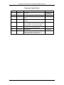
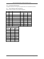
DATA PRODUCT SPECIFICATION FOR MEAN POINT WATER VELOCITY Version 1-01 Document Control Number 1341-00790 2013-08-29 Consortium for Ocean Leadership th 1201 New York Ave NW, 4 Floor, Washington DC 20005 www.OceanLeadership.org in Cooperation with University of California, San Diego University of Washington Woods Hole Oceanographic Institution Oregon State University Scripps Institution of Oceanography Rutgers University Data Product Specification for Mean Point Water Velocity Document Control Sheet Version 0-01 Date 2012-05-31 Description Initial Draft 0-02 0-03 2012-06-01 2012-06-20 0-04 2012-07-02 0-05 2012-07-06 0-06 2012-07-18 1-00 1-01 2012-07-20 2013-08-29 Added accuracy requirements in App B. Incorporated comments from focused review. Clarified where the L0 VELPTMN product is captured. Added note to clarify the current lack of code to transform transmit pulse length and blanking distance from counts to meters. Minor correction to highlighting. Added parameter names and descriptions. Initial Release Updates to description of source of magnetic declination estimate in Section 4.3 and test data set in Section 4.6. Ver 1-01 1341-00790 Author A.Plueddemann, J. Fredericks S. Webster J. Fredericks S. Webster S. Webster S. Webster E. Chapman S. Pearce i Data Product Specification for Mean Point Water Velocity Signature Page This document has been reviewed and approved for release to Configuration Management. OOI Senior Systems Engineer: Date:2012-07-20 This document has been reviewed and meets the needs of the OOI Cyberinfrastructure for the purpose of coding and implementation. OOI CI Signing Authority: Date: 2012-07-20 Ver 1-01 1341-00790 ii Data Product Specification for Mean Point Water Velocity Table of Contents 1 2 Abstract .......................................................................................................................1 Introduction .................................................................................................................1 2.1 Author Contact Information ................................................................................1 2.2 Metadata Information .........................................................................................1 2.3 Instruments.........................................................................................................3 2.4 Literature and Reference Documents ................................................................3 2.5 Terminology........................................................................................................3 3 Theory .........................................................................................................................4 3.1 Description .........................................................................................................4 3.2 Mathematical Theory ..........................................................................................4 3.3 Known Theoretical Limitations ...........................................................................4 3.4 Revision History .................................................................................................4 4 Implementation ...........................................................................................................4 4.1 Overview ............................................................................................................4 4.2 Inputs ..................................................................................................................5 4.3 Processing Flow ...............................................................................................11 4.4 Outputs .............................................................................................................12 4.5 Computational and Numerical Considerations .................................................12 4.6 Code Verification and Test Data Set ................................................................13 Appendix A Example Code .............................................................................................1 Appendix B Aquadopp System Specifications ................................................................1 Appendix C Sensor Calibration Effects ...........................................................................1 Appendix D Matlab Example Code .................................................................................1 Ver 1-01 1341-00790 iii Data Product Specification for Mean Point Water Velocity 1 Abstract This document describes the computation used to calculate the OOI Level 1 Mean Point Water Velocity (VELPTMN) core data product, which is calculated using data from Nortek Aquadopp current meter instruments. This document is intended to be used by OOI programmers to construct appropriate processes to create the L1a velocity point mean product. 2 2.1 Introduction Author Contact Information Please contact Al Plueddeman ([email protected]), Janet Fredericks ([email protected]) or the Data Product Specification lead ([email protected]) for more information concerning the computation and other items in this document. 2.2 Metadata Information 2.2.1 Data Product Name The OOI Core Data Product Name for this product is - VELPTMN The OOI Core Data Product Descriptive Name for this product is - Mean Point Water Velocity The VELPTMN data product is comprised of 3 parameters: Identifier Name Description L0 Units VELPTMN-VLE eastward sea water velocity East component* mm/s VELPTMN-VLN northward sea water velocity North component* mm/s VELPTMN-VLU upward sea water velocity Up component* mm/s * in earth coordinates relative to North True (magnetic variation accounted for) L1 Units m/s m/s m/s 2.2.2 Data Product Abstract (for Metadata) The OOI Level 1a Mean Point Water Velocity core data product characterizes the mean water velocity at a "point" (a volume of several square meters in this case). The mean is created by averaging over time-scales associated with surface gravity waves. The instrument estimates water velocity by measuring the Doppler shift of acoustic signals reflected by particles in the water. The assumption is that the particle is moving with the water and therefore represents the water velocity. 2.2.3 Computation Name N/A 2.2.4 Computation Abstract (for Metadata) The OOI Level 1a Mean Point Water Velocity core data product for water velocity is computed by decoding data ensembles in binary format from the Aquadopp current meter into velocity in units of m/s, in earth coordinates. The velocity components are adjusted to compensate for the earth’s magnetic field effect on the compass heading at the location of the observation. 2.2.5 Instrument-Specific Metadata and Ancillary Data For each deployment, the following metadata from the Hardware Configuration and the Head Configuration structures (described in Sec 4.2) are required: Ver 1-01 1341-00790 Page 1 of 13 Data Product Specification for Mean Point Water Velocity Hardware (Instrument) Serial Number, PIC code version number, HW revision, FirmWare version Recorder Size (in bytes), Velocity Range (Normal or High) Head frequency (kHz), Head type, Head Serial Number, Number of beams, Head configuration, Cell Size (always 1.5 meters) Each velocity record has an associated user configuration record, which includes instrumentspecific metadata. Since the instrument may be reconfigured in the field, the metadata must be associated with each observation. These metadata from the User Configuration include: Average interval (seconds), MeasurementInterval (seconds) Transmit pulse length** (m), Blanking distance** (m) Compass update rate (s), Orientation (up or down), Cell Size (fixed at 1.5m) Sound Speed (measured or assigned in m/s) Salinity (PPT)—note that this is not measured, it is set by the operator prior to deployment (used for sound speed, if it is computed, as recommended) DiagnosticInterval (seconds), NsampDiag, NPingsDiag Measurement load (%) Software version Deployment name ** These parameters are provided in the User Configuration in the units of counts, highlighted in cyan. When it becomes available the code to transform these values from counts to meters will be added to this DPS. Along with the user configuration data, ancillary data from the Velocity Data record can be used to assess data quality or provide supporting information. The following data should be available: Instrument Clock Time Error code (1 Byte-hex) (See description below.) Status code (1 Byte-hex) Battery Voltage (V) Amplitude (counts) SoundSpeed (m/s) Heading, Pitch, Roll (degrees) Pressure (dbar) Temperature (degrees C) Finally, the Aquadopp Diagnostic Data records, if specified in the configuration, should be decoded and available as ancillary data for use in quality assessment. Diagnostic Data have a unique header (see Sec. 4.2) with the rest of the record unpacked according to the Aquadopp Velocity data structure. Diagnostic data include a series of high frequency observations. The first diagnostic data record, if available, can be used to generate a background BeamNoise for each beam, which should be available as time-stamped metadata. The other data in the first diagnostic data record will be meaningless because the transducer is passively recording background noise. The remainder of the diagnostic records, when available, should be stored as an auxiliary data stream, which will look similar to the VELPTMN, but be observed as a high frequency intermittent (perhaps daily) data stream. 2.2.6 Data Product Synonyms Synonyms for this data product are - Ocean Current - Water Velocity 2.2.7 Similar Data Products Velocity Profile (VELPROF) Ver 1-01 1341-00790 Page 2 of 13 Data Product Specification for Mean Point Water Velocity Echo Intensity (ECHOINT) Turbulent Point Water Velocity (VELPTTU) 2.3 Instruments The Data Processing Flow document (DCN 1342-00790) for Aquadopp current meter instruments describes the flow of velocity data from Aquadopps through all of the relevant QC, data product computations and procedures. Please see the Instrument Application in the SAF for specifics of instrument locations and platforms. 2.4 Literature and Reference Documents The electronic file of the reference is stored on Alfresco under REFERENCE>Data Product Specification Artifacts (1341-00790_VELPT). Nortek AS, “System Integrator Manual”, September 2011 Nortek AS, “Aquadopp Current Meter User Manual”, Document No: N3009-100 Revision C 2.5 Terminology 2.5.1 Definitions Definitions of general OOI terminology are contained in the Level 2 Reference Module in the OOI requirements database (DOORS). The following terms are defined here for use throughout this document. Earth (geographic or geodetic) coordinates: Using onboard software, velocity is converted into north, east and up components by using the system compass heading and tilt. The earth coordinates are then referenced to North True by applying a correction for the effect of the magnetic variance on the compass at the specific deployment location at the time of the observation. Data ensemble: A data ensemble consists of the data collected and averaged during the ensemble interval. A data ensemble can contains a header, date, error code, analog input, input voltage, sound speed, compass heading, tilt, pressure, status code, temperature, velocity, signal strength, and a checksum. Signal Strength (amplitude): Backscatter Signal Strength is encoded in counts for each beam. This reflects the concentration of backscattering particles in the sample volume and also can be used to assess the quality of the observation. BCD format: Binary coded decimal is an encoding for decimal numbers in which each digit is represented by its own binary sequence. Four bits are used per digit. The binary sequence is shown in hex. Measurement Load: The Aquadopp current meter can sample at up to 23Hz. A Measurement Load (ping density) of 13% indicates that sampling is 13% of 23 Hz or 3 pings/second throughout the Average Interval. 2.5.2 Acronyms, Abbreviations and Notations General OOI acronyms, abbreviations and notations are contained in the Level 2 Reference Module in the OOI requirements database (DOORS). Ver 1-01 1341-00790 Page 3 of 13 Data Product Specification for Mean Point Water Velocity 2.5.3 Variables and Symbols None 3 3.1 Theory Description Aquadopp instruments characterize velocity by measuring the Doppler shift of acoustic signals reflected by particles in the water. The assumption is that the particle is moving with the water and therefore represents the water velocity. An Aquadopp has three acoustic beams, as well as sensors measuring pressure, temperature, compass heading and tilt. Each beam measures a single velocity component parallel to the beam. Velocity components from the three beams are combined using knowledge of beam geometry, along with measured heading, pitch and roll to create east, north and vertical velocity components. The instrument can be deployed in either upward (e.g. on a multi-function node (MFN)) or downward (e.g. on a near-surface instrument frame (NSIF)) orientation. The internal sensors will detect and compensate appropriately for the instrument orientation. The output data format of an Aquadopp can be either ASCII or binary. For the OOI DPS 134100790, we are describing the binary format product. The L0 mean point water velocity data product output from the Aquadopp driver requires decoding of the binary data and correction for the magnetic field effect on the compass heading to provide the L1a mean point water velocity data product in m/s. 3.2 Mathematical Theory Not applicable. 3.3 Known Theoretical Limitations Too few or too many scattering particles can limit the performance of the Aquadopp. The Aquadopp cannot measure currents if the particles are moving perpendicular to the beam. 3.4 Revision History No revisions to date. 4 4.1 Implementation Overview Appendix A includes example code for unpacking Aquadopp hexadecimal data ensembles from an L0 velocity data product to the L1a velocity data product in units of mm/s. The data stream will include transducer head and hardware configuration files, which should remain constant throughout the deployment. Each velocity data record will have an associated user configuration record. The user configuration record may change, since OOI instruments may be reconfigured during deployment to meet the needs of varying objectives and field conditions. Periodically, a diagnostic record will be generated to enable the assessment of instrument performance (e.g. mooring vibration, which can degrade the quality of the velocity observation). The diagnostic data will be carried forward as ancillary data for potential use in assessment of data quality. When present, a diagnostic data record will have an associated header record with metadata relating to how to read the diagnostic data records that will follow the header. Diagnostic records are typically less frequent than velocity records, although the sampling is at a higher frequency (e.g., 1 Hz for 2 minutes once per day). Ver 1-01 1341-00790 Page 4 of 13 Data Product Specification for Mean Point Water Velocity The instruments shall be configured to always generate data in earth coordinates, which are converted from beam coordinates using the manufacturer’s onboard software. The flow direction is reported in “oceanographic convention” for direction – i.e. “direction to”, as in “North” is flow towards the north. The compass heading is affected by the earth’s magnetic field. As part of the generation of the L1a core product, a rotation on the vector will be applied. 4.2 Inputs Inputs are: L0 VELPTMN velocity data product output from the Aquadopp driver Magnetic Variance (See section 4.3 Step 3b below.) Input Data Formats: Data records are decoded according to formats according to each Sync ID. The Sync ID is described for each record type in the tables below. The Aquadopp point data stream may contain any of the following types of records: SYNC ID STRUCTURE DESCRIPTION A5 00 User Configuration A5 01 Aquadopp Velocity Data A5 04 Head Configuration A5 05 Hardware Configuration A5 06 Aquadopp Diagnostics Data Header A5 80 Aquadopp Diagnostics Data Aquadopp instruments binary record formats for each record type are described below (Nortek AS System Integrator Manual – 2011). Variables that are the L0 VELPTMN data product are highlighted in green. Variables that are directly stored as metadata are highlighted in yellow. Data used for derived metadata are highlighted in cyan. Head Configuration (224 bytes): Size 1 1 2 Name Sync Id Size Offset 0 1 2 2 Config 4 Ver 1-01 Description A5 (hex) 04 (hex) Size of structure in words (2 bytes/word) Head Configuration: bit 0: Pressure sensor* bit 1: Magnetometer* bit 2: Tilt sensor* bit 3: Tilt sensor mounting (0=up, 1=down)a 1341-00790 Page 5 of 13 Data Product Specification for Mean Point Water Velocity 2 2 12 176 22 2 2 Frequency Type SeralNo System Spare NBeams Checksum 6 8 10 22 198 220 222 Head frequency (kHz) Head type Head serial number System Data Spare Number of Beams = B58C (hex) + sum of all bytes in structure * 0=no, 1=yes Hardware Configuration (48 bytes): Size 1 1 2 14 2 2 2 2 2 2 12 4 2 Name Sync Format_ID Size SerialNo Config Frequency PICversion HWrevision RecSize Status Spare FWversion Checksum Offset 0 1 3 4 18 20 22 24 26 28 30 42 46 Description A5 (hex) 05 (hex) Size of structure in words (2 bytes/word) Instrument type/serial number Board configuration: bit 0: recorder installed (0=no, 1= yes) bit 1: compass installed (0=no, 1=yes) Board frequency [kHz] acoustic signal PIC code version number Hardware revision Recorder size (*65536 bytes) Bit 0: Velocity Range (0=normal, 1=high)* Spare Firmware version = B58C(hex) + sum of all bytes in structure User Configuration (512 bytes): Size Name 1 1 2 2 2 2 2 2 2 2 2 Ver 1-01 Description Sync Id Size Offse t 0 1 2 T1 T2 T3 T4 T5 NPings AvgInterval Nbeams 4 6 8 10 12 14 16 18 Transmit pulse length (counts) Blanking distance (counts) Receive length (counts) Time between pings (counts) Time between burst sequences (counts) Number of beam sequences/burst Average interval (seconds) Number of beams (3) A5 (hex) 00 (hex) Size of structure in words (2 bytes/word) 1341-00790 Page 6 of 13 Data Product Specification for Mean Point Water Velocity 2 2 2 2 2 2 2 2 2 2 6 2 6 4 Tim CtrlReg PwrCtrlReg A1 B0 B1 CompassUpdRate RefSys NBins BinLength MeasInt DepName WrapMode clockDeploy DiagInterval 20 22 24 26 28 30 32 34 36 38 40 46 48 54 2 2 Mode AdjSounSpeed 58 60 Timing cotroller mode Power control register Not used Not used Not used Compass update rate (seconds) Coordinate system (0=ENU) Number of cells (1) Cell size (1.5 m for Aquadopp) Measurement Interval (seconds) DeploymentName (0=NoWrap,1=wrap when full) Deployment start time Number of seconds between diagnostic measurements *Mode (see below) User input sound speed adjustment factor 2 NsampDiag 62 # samples in diagnotics mode 2 NbeamsCellDiag 64 2 NpingsDiag 66 #beams/cell no. to measure in diagnostics mode # pings in diagnostics/wave mode 2 2 ModeTest AnalnAddr 68 70 N/A Analog input address 2 2 180 SWVersion Spare VelAdjTable 72 74 76 Software Version Spare Velocity adjustment table 180 2 2 Comments Mode DynPercPos 256 436 438 File comments Wave measurement mode % for wave cell positioning (N/A) 2 2 2 WT1 WT2 WT3 440 442 444 Wave transmit pulse Fixed wave blanking distance (counts) N/A) Wave measurement cell size (N/A) 2 Nsamp 446 Number of diagnostics/wave samples 2 A1 448 Not used 2 B0 450 Not used 2 B1 452 Not used 2 Spare 454 Spare 2 AnaOutScale 456 2 CorrThresh 458 2 Spare 460 Analog output scale factor (16384=1.0, max=4.0) Correlation threshold for resolving ambiguities Spare Ver 1-01 1341-00790 Page 7 of 13 Data Product Specification for Mean Point Water Velocity 2 TiLag2 462 Transmit pulse length (counts) second lag 30 Spare 464 Spare 16 QualConst 494 Stage match filter constants (EZQ) 2 Checksum 510 = B58C (hex) + sum of all bytes in structure *Mode Ver 1-01 58 mode: bit 0: use user specified sound speed (0=no, 1=yes) bit 1: diagnostics/wave mode 0=disable, 1=enable) bit 2: analog output mode (0=disable, 1=enable) bit 3: output format (0=Vector, 1=ADV) bit 4: scaling (0=1 mm, 1=0.1 mm) bit 5: serial output (0=disable, 1=enable) bit 6: reserved EasyQ bit 7: stage (0=disable, 1=enable) bit 8: output power for analog input (0=disable, 1=enable) 1341-00790 Page 8 of 13 Data Product Specification for Mean Point Water Velocity AQUADOPP DIAGNOSTICS DATA HEADER (36 bytes): Size 1 1 2 Name Sync Id Size Offset 0 1 2 Description A5 (hex) 06 (hex) Size of structure in words (2 bytes/word) 2 Records 4 Number of diagnostics samples to follow 2 Cell 6 Cell number of stored diagnostics data 1 Noise1 8 Noise amplitude beam 1 (counts) 1 Noise2 9 Noise amplitude beam 2 (counts) 1 Noise3 10 Noise amplitude beam 3 (counts) 1 2 Noise4 ProcMagn1 11 12 N/A Processing magnitude beam 1 2 ProcMagn2 14 Processing magnitude beam 1 2 ProcMagn3 16 Processing magnitude beam 1 2 2 2 2 2 6 2 ProcMagn4 Distance1 Distance2 Distance3 Distance4 Spare Checksum 18 20 22 24 26 28 34 N/A Distance beam 1 Distance beam 2 Distance beam 3 N/A Spare = B58C (hex) + sum of all bytes in structure Ver 1-01 1341-00790 Page 9 of 13 Data Product Specification for Mean Point Water Velocity AQUADOPP VELOCITY DATA (42 bytes) Aquadopp Diagnostics Data Same as Aquadopp Velocity Data, except Id = 0x80. Size 1 1 2 Name Sync Id Size Offset 0 1 2 1 1 1 1 1 1 2 2 2 2 2 Minute Second Day Hour Year Month Error Analn1 Power SoundSpeed Heading 4 5 6 7 8 9 10 12 14 16 18 2 2 1 1 2 2 2 2 2 1 1 1 1 2 Pitch Roll PressMSB Status PressLSB Temperature VelEastward VelNorthward Upward AmpB1 AmpB2 AmpB3 Fill Checksum 20 22 24 25 26 28 30 32 34 36 37 38 39 40 Description A5 (hex) 01 (hex) Size of structure in number of words (2 bytes/word) Minute (BCD) Second (BCD) Day (BCD) Hour (BCD) Year (BCD) Month (BCD) Error Code (see below) Analog Input 1 Battery voltage (0.1 V) Speed of sound (0.1 m/s) Compass heading (0.1 Degrees) Pitch (0.1 Degrees) Roll (0.1 Degrees) Pressure MSB * Status Code (see below) Pressure LSW* Temperature (0.01 DegC) Eastward flow (mm/s) Northward flow (mm/s) Upward flow (mm/s) Beam1-amp (counts) Beam2-amp (counts) Beam3-amp (counts) Fill byte B58C(hex) + sum of all bytes in structure *Pressure (0.001 dbar) = 65536*PressMSB + PressLSB AQUADOPP ERROR*: Bit 7 Bit 6 Coord CT Transf Sensor 0 = ok, 1= error Bit 5 Beam Number Bit 4 Flash Bit 3 Tag bit Bit 2 Sensor Data Bit 1 Measurement data Bit 0 Compass AQUADOPP STATUS: Bit 7-6 Power level 00= high 3=low (0->3 =6dB) Ver 1-01 Bit 5-4 WakeUp state Bit 3 Roll Bit 2 Pitch Bit 1 Scaling 00=bad 01=power applied 10=break 11=RTC alarm 0=ok 1=out of range 0=ok 1=out of range 0=mm/s 1=0.1mm/s 1341-00790 Bit 0 Orientation 0=up 1=down Page 10 of 13 Data Product Specification for Mean Point Water Velocity 4.3 Processing Flow All data record types have a specific and unique ID number, as noted above. Each record has an associated CHECKSUM. To validate a record, insuring that you have a complete record, a CHECKSUM test should be conducted. Calculate the “checksum” by summing the total number of bytes in the ensemble excluding the 2-bytes with the checksum and add to the value 0x5B8C (hex). Then read the 2-byte checksum at the end of the ensemble and compare it to the calculated value. If they match, then the data ensemble is valid. If they do not match, search for the next header ID number occurrence. The term “decoded” below indicates that all units should be adjusted according to the recommended specifications. The processing flow for the velocity point mean from the Aquadopp is as follows: Step 1: Locate, validate and decode the hardware and head configuration records, when available, to confirm that the deployment has not changed. If it has, then the header and hardware configuration metadata need to be time-stamped and archived. Step 2: The user configuration record should be located, validated and decoded. (Section 2.2.5) should be archived and made available. Associated metadata The RefSys should always be zero (NEU). If the reference system is non-zero, then an error should alert a user that the velocity vectors are not in earth coordinates. Additionally, an operations manager should be notified. Velocity range (scaling bit from the Status word) should always be zero. If the scaling bit is nonzero, the velocity conversion to engineering units will be in error. An operations manager should be notified if the Status Velocity Range bit is set. It is recommended that the sound speed should be calculated, rather than fixed. If the User Configuration Mode indicates that the sound speed is fixed (bit 0 = 1), an operations manager should be alerted. User Configuration metadata will not change frequently, so can be stored with a timestamp to be available for corresponding data records. E.g., a user request data from time 1 – time 2, the user configuration(s) for that time need to be available. Step 3: The velocity data record should be located, validated and decoded. All parameters should be converted to appropriate units, as specified in Section 2.2.5. The parameters VelEastward, VelNorthward, Upward (highlighted in green) should be saved as the L0 VELPTMN data product (units are mm/s). 3a) Health Checks: Instrument Range checks should be conducted from the manufacturer’s specification. The temperature should not be below -4 degC or greater than 40 degC. There should be no velocity component with an absolute velocity greater than 5 meters/second. Also, if the Roll or Pitch bits are set in the STATUS byte, data may be suspect. If the Orientation bit differs from the expected orientation from the Head Configuration, a problem may exist. If the Or if the Scaling bit is not zero, there is a problem. If any of these conditions occur, an instrument health check flag (IH_qcflag) should be set. IH_qcflag should be a structure such as: Ver 1-01 1341-00790 Page 11 of 13 Data Product Specification for Mean Point Water Velocity bit 0: bit 1: bit 2: bit 3: bit 4: bit 5: Orientation (Masked so it’s zero if it matches the Head defined orientation) Scaling (should be zero) Pitch (should be zero) Roll (should be zero) TempQC (set to 1 if range check fails) VelocityQC (set to 1 if velocity range check fails) The Error Byte can be left as is and available as metadata. 3b) The magnetic variation correction must be applied to the velocity components. The magnetic declination estimate for each deployment will be calculated from the World Magnetic Model (WMM) using Latitude, Longitude, and the data time stamp. The WMM is implemented directly in the Ocean Observatories Initiative Network (OOIN) for automated calculation of magnetic declination. For more information on the WMM, go to http://ngdc.noaa.gov/geomag/WMM/DoDWMM.shtml. Positive magnetic variation means that magnetic north is east of true north and negative one means that magnetic north is west of true north. Inputs are horizontal velocity profiles in earth coordinates, eastward flow and northward flow relative to magnetic north, and the magnetic variation. Example code is provided in Appendix D Archive and publish the rotated core L1 product, mean velocity in m/s. 3c) Archive and make available all associated auxiliary data (Section 2.2.5). Step 4: Locate and validate the diagnostics data header, when available. the diagnostic data. This will be used to interpret Step 5: Locate, validate and decode the diagnostics data, when available. Diagnostic data can be processed identically to the data record described in Step 3, above, but it should be treated as ancillary data for quality assessment. For the first A5-80 diagnostic data record the sensors passively listen. This provides a background acoustic noise level that can be used in the computation of a signal to noise ratio (SNR). Therefore, a time-stamped value for BeamNoise (counts) for each of the three beams should be part of the auxiliary diagnostic data. The rest of the first record can be discarded. The following A5-80 records should be treated identically to the Velocity Data Record (Step 3, above). 4.4 Outputs The outputs of the VELPTMN computation are L1 VELPTMN Northward, Eastward and Upward (relative to North True) velocity point mean in m/s The metadata and ancillary data requirements are listed in Section 2.2.5 and highlighted in the “Inputs” tables of record formatting (Section 4.2). See Appendix B for a discussion of the accuracy of the output. 4.5 Computational and Numerical Considerations 4.5.1 Numerical Programming Considerations There are no numerical programming considerations for this computation. No special numerical methods are used. Ver 1-01 1341-00790 Page 12 of 13 Data Product Specification for Mean Point Water Velocity 4.5.2 Computational Requirements Computation estimates are not required for algorithms that are not computationally intensive. 4.6 Code Verification and Test Data Set Below is a table of test data to use for testing the algorithm. L0 VELPTMN Inputs Lat Lon Date Time East Velocity North Velocity Upward Velocity 14.685 -51.044 2005-03-11 21:00:00 -3.2 18.2 -1.1 14.685 -51.044 2005-03-11 22:00:00 0.1 9.9 -0.6 14.685 -51.044 2005-03-11 23:00:00 0 12 -1.4 14.685 -51.044 2005-03-12 00:00:00 2.3 6.6 -2.0 14.685 -51.044 2005-03-12 01:00:00 -0.1 7.4 -1.7 14.685 -51.044 2005-03-12 02:00:00 5.6 3.4 -2.0 14.685 -51.044 2005-03-12 03:00:00 5.1 -2.6 1.3 14.685 -51.044 2005-03-12 04:00:00 5.8 0.2 -1.6 14.685 -51.044 2005-03-12 05:00:00 8.8 -1.5 -1.1 14.685 -51.044 2005-03-12 06:00:00 10.3 4.1 -4.5 L1 VELPTMN Outputs East Velocity North Velocity Upward Velocity -0.085136 0.164012 -0.011 -0.028752 0.094738 -0.006 -0.036007 0.114471 -0.014 0.002136 0.06986 -0.02 -0.023158 0.07029 -0.017 0.043218 0.049237 -0.02 0.056451 -0.009499 0.013 0.054727 0.019311 -0.016 0.088446 0.012096 -0.011 0.085952 0.070017 -0.045 Ver 1-01 1341-00790 Page 13 of 13 Data Product Specification for Mean Point Water Velocity Appendix A Example Code This Appendix contains C code for reading raw binary Aquadopp data files. the Nortek AS, “System Integrator Manual”, September 2011 A-1. It was taken from Structure Definitions #define PD_MAX_BEAMS 3 #define PD_MAX_BINS 128 #define PD_MAX_STAGECELLS 1024 #pragma pack(push) #pragma pack(1) // 1 byte struct member alignment used in firmware /////////////////////////////////////////////////////////////////////// /////// // Clock data (6 bytes) NOTE! BCD format typedef struct { unsigned char cMinute; // minute unsigned char cSecond; // second unsigned char cDay; // day unsigned char cHour; // hour unsigned char cYear; // year unsigned char cMonth; // month } PdClock; /////////////////////////////////////////////////////////////////////// /////// // Aquadopp diagnostics header data typedef struct { unsigned char cSync; // sync = 0xa5 unsigned char cId; // identification = 0x06 unsigned short hSize; // total size of structure (words) unsigned short nRecords; // number of diagnostics samples to follow unsigned short nCell; // cell number of stored diagnostics data unsigned char cNoise[4]; // noise amplitude (counts) PdClock clock; // date and time unsigned short hSpare1; unsigned short hDistance[4]; // distance unsigned short hSpare[3]; short hChecksum; // checksum } PdDiagHead; /////////////////////////////////////////////////////////////////////// /////// // Aquadopp velocity data 3 beams typedef struct { unsigned char cSync; // sync = 0xa5 unsigned char cId; // identification (0x01=normal, 0x80=diag) unsigned short hSize; // size of structure (words) PdClock clock; // date and time short hError; // error code: // bit 0: compass (0=ok, 1=error) // bit 1: measurement data (0=ok, 1=error) // bit 2: sensor data (0=ok, 1=error) // bit 3: tag bit (0=ok, 1=error) // bit 4: flash (0=ok, 1=error) // bit 5: // bit 6: serial CT sensor read (0=ok, 1=error) unsigned short hAnaIn1; // analog input 1 Ver 1-01 1341-00790 Appendix Page A-1 Data Product Specification for Mean Point Water Velocity unsigned short hBattery; // battery voltage (0.1 V) union { unsigned short hSoundSpeed; // speed of sound (0.1 m/s) unsigned short hAnaIn2; // analog input 2 } u; short hHeading; // compass heading (0.1 deg) short hPitch; // compass pitch (0.1 deg) short hRoll; // compass roll (0.1 deg) unsigned char cPressureMSB; // pressure MSB char cStatus; // status: // bit 0: orientation (0=up, 1=down) // bit 1: scaling (0=mm/s, 1=0.1mm/s) // bit 2: pitch (0=ok, 1=out of range) // bit 3: roll (0=ok, 1=out of range) // bit 4: wakeup state: //bit 5:(00=bad power,01=break,10=power applied,11=RTC alarm) // bit 6: power level: // bit 7: (00=0(high), 01=1, 10=2, 11=3(low)) unsigned short hPressureLSW; // pressure LSW short hTemperature; // temperature (0.01 deg C) short hVel[3]; // velocity unsigned char cAmp[3]; // amplitude char cFill; short hChecksum; // checksum } PdMeas; A-2. Sample code for decoding the Aquadopp data structure typedef struct { unsigned char cSync; // sync = 0xa5 unsigned char cId; // identification (0x01=normal, 0x80=diag) unsigned short hSize; // size of structure (words) PdClock clock; // date and time short hError; // error code short hSpare; unsigned short hBattery; // battery voltage (0.1 V) unsigned short hSoundSpeed; // speed of sound (0.1 m/s) short hHeading; // compass heading (0.1 deg) short hPitch; // compass pitch (0.1 deg) short hRoll; // compass roll (0.1 deg) unsigned char cMSB; // pressure MSB char cStatus; // status code unsigned short hLSW; // pressure LSW short hTemperature; // temperature (0.01 deg C) short hVel[3]; // velocity (mm/s) unsigned char cAmp[3]; // amplitude (counts) char cFill; short hChecksum; // checksum } PdMeas; { . . . Ver 1-01 1341-00790 Appendix Page A-2 Data Product Specification for Mean Point Water Velocity PdMeas meas; SYSTEMTIME st; double dVel[3]; double dAmp[3]; short hChecksum; double dPressure; double dBattery; double dHeading; double dPitch; double dRoll; double dTemperature; // Assuming three beams // Checksum control if (meas.hChecksum != Checksum((short *)&meas,meas.hSize - 1)) { // Handle the error. } st = ClockToSystemTime(meas.clock); dVel[0] = (double)meas.hVel[0] * 0.001; dVel[1] = (double)meas.hVel[1] * 0.001; dVel[2] = (double)meas.hVel[2] * 0.001; dAmp[0] = (double)meas.cAmp[0]; dAmp[1] = (double)meas.cAmp[1]; dAmp[2] = (double)meas.cAmp[2]; dPressure = (65536.0*(double)meas.cMSB + (double)meas.hLSW)*0.001; dBattery = (double)meas.hBattery * 0.1; dHeading = (double)meas.hHeading * 0.1; dPitch = (double)meas.hPitch * 0.1; dRoll = (double)meas.hRoll * 0.1; dTemperature = (double)meas.hTemperature * 0.01; . . }////////////////////////////////////////////////////////////////////// / // Convert from BCD time to system time SYSTEMTIME ClockToSystemTime(PdClock clock) { SYSTEMTIME systime; WORD wYear; wYear = (WORD)BCDToChar(clock.cYear); if (wYear >= 90) { wYear += 1900; } else { wYear += 2000; } systime.wYear = wYear; systime.wMonth = (WORD)BCDToChar(clock.cMonth); systime.wDay = (WORD)BCDToChar(clock.cDay); systime.wHour = (WORD)BCDToChar(clock.cHour); systime.wMinute = (WORD)BCDToChar(clock.cMinute); systime.wSecond = (WORD)BCDToChar(clock.cSecond); systime.wMilliseconds = 0; return systime; } /////////////////////////////////////////////////////////////////////// Ver 1-01 1341-00790 Appendix Page A-3 Data Product Specification for Mean Point Water Velocity // Convert from BCD to char unsigned char BCDToChar(unsigned char cBCD) { unsigned char c; cBCD = min(cBCD,0x99); c = (cBCD & 0x0f); c += 10 * (cBCD >> 4); return c; } /////////////////////////////////////////////////////////////////////// // Compute checksum short Checksum(short *phBuff,int n) { int i; short hChecksum = 0xb58c; for (i=0; i<n; i++) hChecksum += phBuff[i]; return hChecksum; } Ver 1-01 1341-00790 Appendix Page A-4 Data Product Specification for Mean Point Water Velocity Appendix B Aquadopp System Specifications The algorithm output accuracy for the OOI L1a VELPTMN core data product calculated by this algorithm is equivalent to the accuracy of the instrument. The manufacturer, Nortek-AS, provides accuracy as stated below (from Aquadopp User Manual): Velocity Measurement: Range: +- 5 m/s Accuracy: 1% of measured value +- 0.5 cm/s Max sampling rate (output): 1 second Internal sampling rate: 23Hz Temperature (thermistor embedded in head): Range: -4 DegC – 40 DegC Accuracy/Resolution: 0.1 DegC/0.01DegC Time response: 10 minutes Compass (flux-gate with liquid tilt) Maximum tilt: 30 Degrees Accuracy/Resolution: 2 Deg/0.1 Deg Time response: user defined Tilt (liquid level) Accuracy/Resolution: 0.2 Deg/0.1 Deg Up or down: Automatic detect Pressure (piezoresistive) Range: 0-200 m (standard) Accuracy: 0.25% Resolution: Better than 0.005% of full scale/sample Relevant requirements from The OOI requirements database (DOORS, L2_Science_Requirements_ReferenceOnly_Baseline_Version_2.24 exported from DOORS SL CCB 2012-05-02) are listed below. L2-SR-RQ-3274 L2-SR-RQ-3736 L2-SR-RQ-3737 L2-SR-RQ-3739 L2-SR-RQ-3740 L2-SR-RQ-3158 L4-CG-IP-RQ-248 L4-CG-IP-RQ-250 L4-CG-IP-RQ-484 L4-CG-IP-RQ-256 L4-CG-IP-RQ-257 Ver 1-01 Single Point Water Velocity shall be measured with a speed accuracy of +/-1% of measured value +/-1 cm/s. Single Point Water Velocity shall be measured with a speed resolution of 0.1 cm/s. Single Point Water Velocity shall be measured with a single sample speed precision of 3 cm/s. Single Point Water Velocity shall be measured with a direction accuracy of +/-2 degrees. Single Point Water Velocity shall be measured with a direction resolution of 0.1 degrees. Mean Point water velocity at the seafloor shall be measured to a value no less than 200 cm/s. Single Point Water Velocity instruments shall have a speed accuracy of +/-1% of measured value +/-1 cm s-1. Single Point Water Velocity instruments shall have a speed resolution of 0.1 cm s-1. Single Point Water Velocity instruments shall have a single sample speed precision of no greater than 3 cm s-1. Single Point Water Velocity instruments shall have an absolute direction accuracy of +/- 2 degrees. Single Point Water Velocity instruments shall have a direction resolution of 0.1 degrees. 1341-00790 Appendix Page B-1 Data Product Specification for Mean Point Water Velocity Appendix C Sensor Calibration Effects None. Appendix D Matlab Example Code Matlab example code for transformation to correct for magnetic variance: % Apply magnetic variation ‘Degrees’ (see Section 4.3 Step 3b) % Note: use of atan2 changes heading range from 0-360 to +/-180. % Note: example data provided used magvar=-17.6 % east/north are velocities relative to magnetic north magvar = Degrees * pi/180; % convert to radians i = sqrt(-1); unit_vec = sin(hd*pi/180) + i* cos(hd*pi/180); u = real(unit_vec)*cos(magvar) + imag(unit_vec)*sin(magvar); v = imag(unit_vec)*cos(magvar) - real(unit_vec)*sin(magvar); hd = atan2( u, v ) * 180/pi; u = east*cos(magvar) + north*sin(magvar); v = north*cos(magvar) - east*sin(magvar); east_rotated = u; north_rotated = v; magvar = magvar * 180/pi; % save value in degrees Ver 1-01 1341-00790 Appendix Page C-1