1
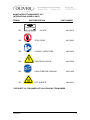
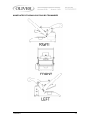
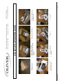
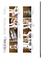
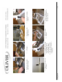
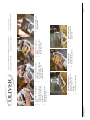
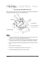
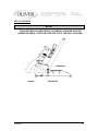
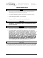
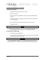
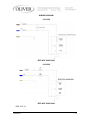
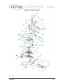
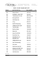
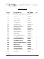
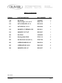
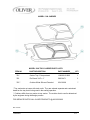
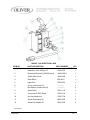
Walker, Michigan, U.S.A. 49534-7564 USER’S OPERATING AND INSTRUCTION MANUAL MODEL 1308-C & 1308-N HEAT SEALER 1308S20000CV1 INDEX Section Description Document No. Page No. DESCRIPTION/SPECIFICATIONS ----------------------------1308S20013 ------------------------- 1-1 Description ------------------------------------------------------------------------------------------------- 1-1 Specifications----------------------------------------------------------------------------------------------- 1-1 GENERAL SAFETY INSTRUCTIONS-------------------------1308S20014-------------------------- 2-1 Lockout-Tag out-------------------------------------------------------------------------------------------- 2-1 NAMEPLATE/PICTOGRAMS PART LIST--------------------1308S20015-------------------------- 3-1 Nameplate/Pictogram Locations by Item Number------------------------------------------------ 3-2 SETUP AND OPERATION GUIDE-----------------------------1308S20036-------------------------- 4-1 Set up continued------------------------------------------------------------------------------------------- 4-2 OPERATING PROCEDURES-----------------------------------1308S20017--------------------------- 5-1 Adjustment and Quality ---------------------------------------------------------------------------------- 5-2 TECHNICAL SPECIFICATIONS------------------------------- 1308S20018--------------------------- 6-1 CLEANING PROCEDURES-------------------------------------1308S20019---------------------------- 7-1 Cleaning Procedures-------------------------------------------------------------------------------------- 7-2 Cleaning Cutter Blade------------------------------------------------------------------------------------ 7-2 Replacing and Checking Gaskets---------------------------------------------------------------------- 7-3 Disposal Procedure---------------------------------------------------------------------------------------- 7-3 TROUBLE SHOOTING---------------------------------------------1308S20020---------------------------8-1 WIRING DIAGRAM--------------------------------------------------1308S20021---------------------------9-1 1308-C HEAT SEALER---------------------------------------------1308S20022--------------------------10-1 1308 Heat Sealer Parts Lists----------------------------------------------------------------------------10-2 1308 Heat Sealer Parts Lists Con’t--------------------------------------------------------------------10-3 1308 Tray Carrier-------------------------------------------------------------------------------------------10-4 1308 Tray Carrier Parts List------- ----------------------------------------------------------------------10-4 WARRANTY ------------------------------------------------------- GEN 050816 WARRANTY PROCEDURE------------------------------------ GEN 050817 RETURNED PARTS POLICY --------------------------------- GEN 050818 REV. 1/26/09 1308S20012 0-1 THIS PAGE WAS INTENTIONALLY LEFT BLANK. GEN020319 DESCRIPTION/SPECIFICATIONS Description The Oliver Model 1308 Heat Sealer is designed and manufactured to ensure a user friendly operation of producing film lidded trays with a cost effective approach. The manually operated machine operates with either a 120 or 230 V.A.C. outlet. The machine was designed to be compact to limit the amount of table space needed to operate. Specifications Space Requirements, (Shown with standard options) Model 1308-C & 1308-N (All dimensions are shown approximate) Shipping Weight – 65 lbs (30 Kg) (approximate) Net Weight – 60 lbs (27 Kg) (approximate) 1308S20013 1-1 THIS PAGE WAS INTENTIONALLY LEFT BLANK. GEN020319 GENERAL SAFETY INSTRUCTIONS WARNING IT IS ESSENTIAL THAT ALL OPERATORS AND MAINTENANCE PERSONNEL OBSERVE THE FOLLOWING SAFETY PRECAUTIONS. IMPROPER INSTALLATION, MAINTENANCE, OR OPERATION OF THIS EQUIPMENT MAY CAUSE SERIOUS INJURY. 1. Read this manual before attempting to operate your heat sealer. Never allow an untrained person to operate or service this unit. 2. Observe all caution and warning labels affixed to the machine. 3. Always unplug the machine before cleaning or servicing. 4. Do not submerge in water. Do not hose down. 5. Use original replacement parts. 6. Wear proper, personal, protective, safety equipment if necessary. 7. Keep hands away from moving parts of the machine while it is operating. 8. In addition to these general safety instructions, please follow the more specific safety instructions provided throughout the rest of this operating and instruction manual. WARNING TO PROVIDE CONTINUED PROTECTION FROM ELECTRICAL SHOCK, CONNECT TO PROPERLY GROUNDED OUTLETS ONLY. LOCKOUT-TAGOUT It is very important that the unit should be free of any unexpected energization, or be able to release hazardous energy during service or maintenance activities. Therefore, always switch the machine off before unplugging the power cord from BOTH the unit and the wall. 1308S20014 2-1 NAMEPLATE/PICTOGRAM PARTS LIST (INTERNATIONAL MODELS ONLY) ITEM NO PART DESCRIPTION BAKERY PRODUCTS BV MODEL NO. 601 PART NUMBER Spurkt 3 35804 AR Venray, The Netherlands SERIAL NO. VOLTAGE CYCLE KW MFG’D PHASE MASS AMPS “OLIVER” 6401-5076 603 “STAY CLEAR” 6401-9043 604 “CONSULT OPERATORS…..” 6400-3039 605 “ELECTRICAL SHOCK” 6400-5009 606 “UNPLUG BEFORE OPENING” 6402-1028 607 “HOT SURFACE” 6400-8021 **SEE SHEET 3-2 FOR NAMEPLATE LOCATIONS BY ITEM NUMBER 1308S20015 3-1 NAMEPLATE/PICTOGRAM LOCATIONS BY ITEM NUMBER 1308S20015 3-2 1308S20034 Shipping carton Snip the plastic ties on the electrical cord Install Counterweight Step One Open carton as shown Remove parts and packing material Step Two Remove the 1308 Unit 1308 SETUP & OPERATION GUIDE Step Three Place the 1308 Unit on a table or cart 3-1 1308S20034 Step Four Install holder and knob on other side Install Holder Step One Install the two counterweight holders and plastic knobs Install Plastic Knob and tighten Step Two Install holder Step One Showing the counterweight installed Install Plastic Knob and tighten 3-2 1308S20034 Plug power cord in 115V wall socket Hold down on the handle and remove the strap Lift Handle With handle in the upright position push in on the rocker switch to the “I” position (POWER ON) Allow 30 minutes for the heater platen to heat up to temperature Install tray carrier Step One Handle shown in the upright position Using the locating pins in the tray carrier and holes in the frame as shown Install power cord plug as shown 3-3 1308S20034 Place a tray in the tray carrier Pull the film forward ¼” beyond edge of tray Lift handle to the upright position Remove the sealed tray Pull the film from the top of the roll Lift up the black film pinch roller and slid the film under it as shown Pull the handle down all the way to this position and hold it down for ½ to 1 seconds The film is cut at this time Install film roll in back of unit Pull the film from the top of the roll towards the front of the unit Placing it between the two white guide rollers Using both hands pull the handle down Shown in the upright position ready to seal another tray 3-4 OPERATING PROCEDURES 1. CAUTION – To provide continued protection against risk of electric shock, connect only to properly grounded outlets only. Avoid the use of extension cords. NOTE: It should take approximately 15 minutes for the machine to warm up to operating temperature. 2. Place tray carrier in its designated area with the dowel pins facing down 3. Place filled tray in tray carrier. Make sure the food in the tray is not higher than the flange of the tray 4. Grasp the corners of the film and pull it straight across the tray going a ¼ inch past the flange of the tray 5. Pull handle down with both hands until it stops. Hold the handle down for approximately 2 seconds. 6. Lift the handle to its upright position. 7. Remove tray from tray carrier. 8. Repeat steps 4 thru 8 CAUTION IT IS NOT RECOMMENDED TO LEAVE THE MACHINE ON WHEN IT WILL BE OUT OF OPERATION FOR AN EXTENDED PERIOD OF TIME. Rev 7-28-2015 1308S20017 5-1 ADJUSTMENT AND QUALITY Your OLIVER Model 1308 was tested at the factory using Oliver trays and film. NOTE THE TEMPERATURE CANNOT BE ADJUSTED BY THE OPERATOR The heater platen temperature is factory set at approximately 300°F (Approx. 150°C). Contact the Oliver Service Department if you suspect the heated platen temperature is not correct. It is necessary to periodically check for a proper seal. This can be done by pull the film over an empty tray carrier, sealing it like normal and peeling the film. If there is a proper seal, the pattern on the film should be a complete outline of gasket material provided. A poor seal will occur if the product in the tray contaminates the tray flange or the pressure generated by the sealing mechanism is less than 15lbs. The pressure can be adjusted by removing the acorn nut atop the center arm and giving a few turns to the nut on the heater adjustment bolt. This will expose more threads between the casting and the sealing mechanism, therefore, generating more pressure. Under different operating conditions, it may be necessary to increase or decrease the sealing time. This is done by varying the length of time the operating handle is in the down position. Holding the handle down longer makes the seals stronger. Although a stronger seal may cause shredding or tearing of the film when removing film from tray. REV. 7-10-15 1308S20017 5-2 THIS PAGE WAS INTENTIONALLY LEFT BLANK. GEN020319 BASIC MACHINE COMPONENTS AND SET UP Before proceeding further, take a moment to familiarize yourself with the identification of the machine components as shown in the illustration below. SET UP 1. Carefully remove the Model 1308 from the box. Check to make sure the order is complete, and it has not been damaged during shipment. 2. Place the unit in a suitable location which provides an adequate working space. The location must be sturdy, level, and capable of holding 60lbs. per machine. 3. Remove all packaging materials and shipping restraints such as plastic ties and tape. 4. Raise the handle to full extension. 5. Place film roll in designated area towards the rear of the unit. 6. Thread film through the film pinch roller as shown below. 1308S20016 4-1 SET UP CONTIUED NOTE: FILM SUPPLIED BY OLIVER PRODUCTS COMPANY IS WOUND WITH THE ADHEASIVE SIDE IN. FEED FILM FROM THE TOP OF THE ROLL AS SHOWN. 1308S20016 4-2 CLEANING AND MAINTENANCE NOTE • These cleaning recommendations are not meant to replace plant standard manufacturing procedures or regulatory requirements. • If the machine has been in operation, allow the unit to cool before cleaning. • Do not submerge unit in water. Do not wash down. • Tray carrier is NOT recommended for automatic dishwashers CAUTION • CAUTION HOT: The heated platen is HOT! Caution must be used to prevent injury from heated platen. WARNING • Make sure the unit has been unplugged for a minimum one hour before cleaning. • It is important that the surface of the heater platen is kept clean and smooth. Regularly clean the OLIVER Model 1308 with a mild cleaner and a damp cloth. If food product comes in contact with the surface of the platen, it tends to burn on and become hard. This results in an irregular surface on the face of the platen which can result in poor seals. If this happens, it will be necessary to remove this contaminate material. When cleaning care must be taken to avoid scratching or gouging the surface of the platen. DO NOT SCRAPE THE SURFACE OF THE PLATEN WITH SHARP OBJECTS AND AVOID THE USE OF METAL TOOLS. The use of plastic or soft-metal scouring pads such as SCOTCH BRITE™ or CHORE BOY® provides a safe and effective means of cleaning the platen. Be sure to wipe all surfaces with a sanitizing agent after cleaning. CAUTION IF CLEANING THE HEATER PLATEN WHILE THE UNIT IS STILL ON, MAKE SURE THAT HAND PROTECTION IS WORN AT ALL TIMES TO PREVENT SKIN CONTACT. 1308S20019 7-1 CLEANING AND MAINTENANCE CONTINUED CLEANING PROCEDURES 1. Unplug the unit and allow one hour for cooling. 2. Remove tray carrier. 3. Place tray carrier in the dishwasher or wipe down with a standard cleaning solution. 4. Lift operating handle to expose the bottom side of the heater, and then wipe off the heater platen. 5. Use a sanitizing solution to spray and wipe down the rest of the unit. 6. Replace tray carrier NOTE THE DELRIN LINKS LOCATED ATOP THE UNIT SHOULD BE LUBRICATED WITH A FOOD GRADE MATERIAL ONCE A MONTH TO PREVENT WEARING. CLEANING THE CUTTER BLADE 1. Lift handle up to its resting position. 2. Use a damp cloth with sanitizing solution to wipe off any access food particles located on the back of the cutter blade. CAUTION THE CUTTER BLADE IS SHARP. USE A PROTECTIVE GLOVE TO DO THIS CLEAING OPERATION. FAILURE TO DO SO MAY RESULT IN SERIOUS INJURY. 1308S20019 7-2 CLEANING AND MAINTENANCE CONTINUED REPLACING AND CHECKING GASKETS • If there are any gouges, cuts or gaps in the gasket, the gasket will have to be replaced. • Be sure to replace all the gaskets not just the piece that is damaged. • When reinstalling gaskets, the gasket must be seated all the way down in the groove. • Do not stretch gasket when reinstalling. • After the new gaskets are installed, place the tray carrier up side down on a flat surface and check to see if the newly installed gasket is even. • If not even, depress or lift gasket to provide an even heat sealing surface. • It is necessary to periodically check for a proper seal. This can be done by pull the film over the empty tray carrier, sealing it like normal and pulling the film. If there is a proper seal, the pattern on the film should be a complete outline of the edges of the tray. DISPOSAL PROCEDURE When considering disposing of your unit, please contact local authorities for any special instructions. 1308S20019 7-3 THIS PAGE WAS INTENTIONALLY LEFT BLANK. GEN020319 WIRING DIAGRAM 1-60-120V REF. W/D 1308C12002 1-60-230V REF. W/D 1308C12000 REV. 4-27-12 1308S20021 9-1 MODEL 1308 HEAT SEALER Rev 1/31/12 1308S20022 10-1 MODEL 1308 HEAT SEALER PARTS LISTS ITEM NO 001 PART DESCRIPTION Base PART NUMBER______QTY 1308-0015-301 1 002 Bumper-Rubber 5902-0035 6 003 PIN-DOWEL 1/4X3/4" STST 5835-6475 4 004 Tube-Aluminum 7/8” O.D. 4639-1414-1116 1 005 Bearing-Roll End 5252-3002 2 006 Guide-Roller Film 1908-0041 2 007 O-ring 6909-3211 2 008 Rod-Film Dispensing 1308-0018 1 009 SCREW-SOCSET CUPPT 5842-6120 4 010 Tube-Film Shaft 1308-0016 1 011 Rod Pinch Roller 1308-0048-1 1 012 Washer flat 5851-9306 2 013 Spacer-Pinch Roller 1308-0049-1 2 014 Pinch Roller Tube 1308-0050 1 015 WASHER-#10 FLAT 5851-9302 2 016 WASHER-LOCK 5851-9394 2 017 SCREW-HEX HD 10-24 5843-1231 2 018 (See Third Assembly) ------------- 101 Arm-Center 1308-0014 1 102 Shaft-Center Arm Link 1308-0001 1 103 BEARING-SINT BRZ FLNG 5254-3215 4 104 Clip-E Style (3/4” Shaft) 5840-2841 8 105 Link-Center Arm 5502-1900 2 Rev 1/31/12 1308S20022 10-2 PARTS LIST CONTINUED ITEM NO PART DESCRIPTION PART NUMBER______QTY 106 Shaft-Mid Pivot 1308-0002 1 108 PLUG-HOLE DOME WHITE 3/16" 5769-3000 4 109 Weight-Counter 1308-0042-1 1 110 Counter Weight 1308-0065 2 111 COVER-CLAMP 1908-0262 2 201 Assembly-Handle 1308-0500-1 1 202 Shaft-Handle Pivot 1308-0007-001 2 203 BEARING SINT BRZ SLV 5254-0306 2 301 301 Platen-120V Heater Platen-230V Heater 1308-0061-1 1308-0061-002 1 1 302 Spring-Compression 7015-2200 6 303 Blade-Cutting 1308-0011-1 1 304 Plate-Cutting Blade Mounting 1308-0056 1 305 Spacer-Blade Mounting 1308-0024-001 3 306 NUT-HEX MACHINE #10-24 5832-0578 3 307 Screw-Shoulder 1/4 x 3/8 5842-8997 3 308 WASHER-NATURAL NYLON FLAT 5851-8120 3 309 WASHER-LOCK 5851-9355 3 310 Spring-Compression 2” 7014-4203 2 311 Channel-Spring Backer 1308-0055 1 312 Screw-Shoulder ¼-28 x 3/4 4560-0908-1201 4 313 Cover-Heater 1308-0058 1 Rev 1/31/12 1308S20022 10-3 PARTS LIST CONTINUED ITEM NO PART DESCRIPTION PART NUMBER______QTY 314 Bar-Pusher 1308-0057 1 315 Bolt-Carriage ½-13 x 4-1/2” 5804-1722 1 316 NUT-ACORN STD 1/2"-13 5831-8100 1 317 NUT-HEX FULL 1/2-13 5832-0524 2 318 WASHER-1/2" SPRING LOCK 5851-9011 1 319 WASHER-7/16" FLAT 5851-9307 1 320 Box-Relief 1308-0059 1 321 Bushing-Strain Relief 5765-1110 2 322 Nut-Hex Head Lock (PG-11) 5766-7786 2 323 SCREW-ROUND HD 6-32 5843-5210 4 325 SCREW-HEX HD 1/4-20 5843-1005 2 326 WASHER-LOCK 1/4" 5851-9357 2 Rev 1/31/12 1308S20022 10-4 MODEL 1308 CARRIER MODEL 1308 TRAY CARRIER PARTS LISTS ITEM NO PART DESCRIPTION PART NUMBER______QTY 701* Carrier-Tray 3 Compartment 1308-0013-0003 1 702 Pin-Dowel 3/16” x 1” 5835-6471 2 703** Cushion-White Silicone Extruded 6516-0028 ** * Tray carries do not come with stock units. They are ordered separate and customized based on the tray that is being used in the sealing operation. ** Cushions differ from tray carrier to tray carrier. The cushion that is used is determined by the engineer during the design process. FOR SERVICE PARTS CALL OLIVER PRODUCTS @ 800-253-3893 Rev 1/31/12 1308S20022 10-5 MODEL 1308 ELECTRICAL BOX ITEM NO PART DESCRIPTION PART NUMBER______QTY 1 Assembly- Cord & Plug 6 FT 5765-8374 1 2 Enclosure-Electrical (1308-CE) small 1308-0060-2 1 3 Switch Plate Cover 1308-0066 1 4 Plate-Elbow 5 Light-Pilot 5709-0021 1 6 Cover (comes with #1) ------------ 1 7 Box Screws (comes with #1) ------------- 4 8 Strain Relief 5765-1110 1 9 Connector-90 PVC Elbow 5765-6312 1 10 Nut-Hex Head Lock 5766-7786 1 11 Screw-Flat Head 4-40 5843-5022 2 12 Screw-Pan Head 4-40 5543-5520 2 1308-0071 1 Rev 4/27/12 1308S20022 10-6 WARRANTY PROCEDURE 1. If a problem should occur, either the dealer or the end user must contact the Customer Service Department and explain the problem. 2. The Customer Service Manager will determine if the warranty will apply to this particular problem. 3. If the Customer Service Manager approves, a Work Authorization Number will be generated, and the appropriate service agency will perform the service. 4. The service dealer will then complete an invoice and send it to the Customer Service Department at Oliver Packaging & Equipment Company. 5. The Customer Service Manager of Oliver Packaging & Equipment Company will review the invoice and returned parts, if applicable, and approve for payment. GEN 050817 RETURNED PARTS POLICY This policy applies to all parts returned to the factory whether for warranted credit, replacement, repair or re-stocking. Oliver Packaging & Equipment Company requires that the customer obtain a Return Material Authorization (RMA) number before returning any part. This number should appear on the shipping label and inside the shipping carton as well. All parts are to be returned prepaid. Following this procedure will insure prompt handling of all returned parts. To obtain an RMA number contact the Repair Parts Deptartment toll free at (800) 253-3893. Parts returned for re-stocking are subject to a RE-STOCKING CHARGE. Thank you for your cooperation, Repair Parts Manager Oliver Packaging & Equipment Company GEN 050818