1
Procedure #1: Digital Circuits
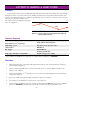
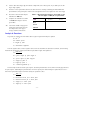
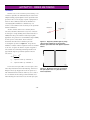
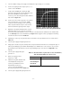
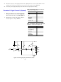
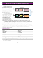
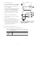
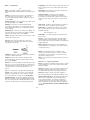
The word "digital" in fiber optics means much the same as it does in electronics. Digital gates, circuits or systems are
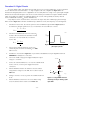
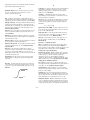
those in which there are two defined states — a "high" or digital 1, and "low", a digital 0. See Figure 8.2 for an
illustration. In all digital systems a "low" or digital 0 does not necessarily mean zero voltage or zero optical signal. A digital
0 means a lower state than the digital 1 state. In the electronics industry, the definitions of a digital 1 and 0 are defined
within a logic family. For example, the established limits for the electronic TTL logic family are that Vhigh must be
between 2.0 and 5.0 volts and V low between 0 and 0.8 volts.
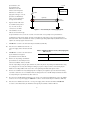
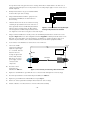
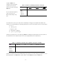
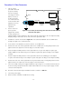
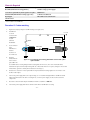
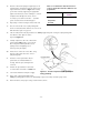
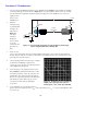
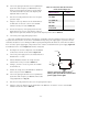
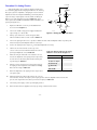
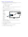
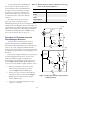
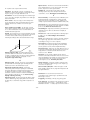
A very simple electronic circuit that can be connected to the output of any TTL or CMOS logic gate for driving a
LED is shown in Figure 8.3. It will drive an LED with up to 50 mA of current, and a frequency of several megahertz.
1.
Calculate the resistor value, Rc, needed to permit a current of 20 mA through the LED in Figure 8.3 when
the transistor is saturated. Assume the Vce(sat)=.2 volts and the Vf for the LED to be 1.8 volts.
Rc =
2.
5 − Vf −Vce(sat )
Ic
Calculate the maximum value of the base resistor, Rb,
needed to drive the transistor into saturation if Vi was
connected to + 5 volts. Assume Vbe=.7 volts and
h fe(min)= 50.
Rb =
5 − Vbe(sat )
high
low
Ic
hfe
Figure 8.2 The two states of digital and
fiber optic systems.
3.
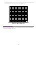
Choose resistors from the kit that are closest to the
calculated Rc and one-half the calculated R b. See Table
1.2 for choices.
4.
Assemble the circuit shown in Figure 8.3 on your solderless breadboard. Use the pin diagrams found in the
APPENDIX to identify device connections.
5.
Turn on the variable voltage power supply and adjust the output
voltage to + 5 volts DC.
6.
Connect the end of R b marked Vi to + 5 volts. The red LED should
now be on. If not, check the power supply and electrical
connections.
7.
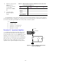
With the multimeter measure the transistor collector-to-emitter
voltage and the voltage across the LED, then record the results in
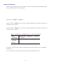
Table 8.1.
+ 5 volts
Rc
Red
LED
Vi
2N3904
Rb
8.
Change V i from the + 5 volts to ground. The red LED should now
be off.
9.
With the multimeter, measure the collector-to-emitter voltage
across the transistor and record the result in Table 8.1.
- 36 -
1475.eps
Figure 8.3 Single NPN transistor
switching circuit for driving a fiber
optic LED.