1
1.
2.
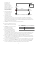
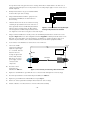
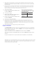
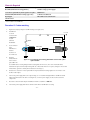
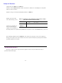
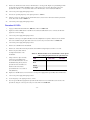
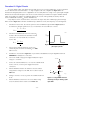
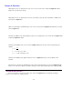
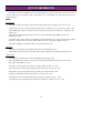
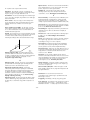
Replace the simple resistor located on the
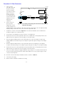
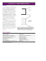
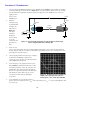
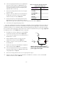
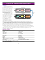
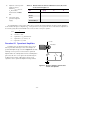
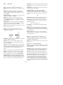
breadboard with the circuit shown in Figure
9.4. (Ignore Cl for now.)
4.
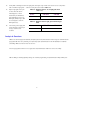
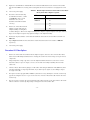
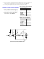
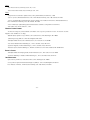
For the three values of R f listed in Table 9.2,
measure Vp-p, tr and tf with an oscilloscope.
Record the measured results in Table 9.2.
7.
3
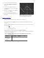
Place one end of the .001 µf capacitor (C1) at
the output of the operational amplifier and the
other end to ground as shown in the dashed
outline in Figure 9.4.
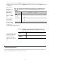
Record in the last row of
Table 9.2 Vp-p, tr and tf of
this receiver circuit with the
added load capacitance.
2
-
7
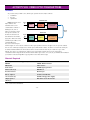
LM741
Turn on the signal generator.
6.
+5 volts
Turn on the power supply and adjust its output
to provide a voltage of +/- 5 volts DC.
3.
5.
Rf
Photodiode
+
Vo
6
4
C1
1 kΩ
1525.eps
-5 volts
Figure 9.4 Non-inverting fiber optic receiver using an
operational amplifier.
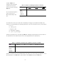
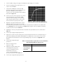
Table 9.2 Measured data for various termination resistors, Rf, in the
circuit shown in Figure 9.4.
Turn off the signal generator
and power supply.
Rf
V p-p
tr
tf
100 kΩ
47 kΩ
10 kΩ
10 kΩ ||.001 µf
Procedure #3: Discrete Designs
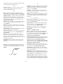
Although operational amplifiers are readily available and easy to use, they sometimes lack the required frequency
bandwidth for some applications. For these applications, discrete transistor amplifiers are often the answer. Examples of
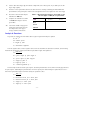
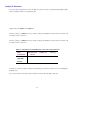
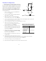
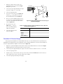
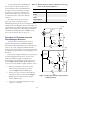
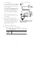
two discrete bipolar-transistor amplifier circuits are shown in Figure 9.5.
1.
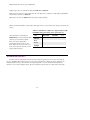
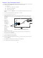
Replace the operational amplifier and associated circuitry on the breadboard with the circuit shown in Figure
9.5 (a). Reposition the photodiode and device mount as needed.
2.
Turn on the power supply and adjust the output connected to the discrete transistor receiver to + 5 volts DC.
3.
Turn on the signal generator.
4.
Measure the Vp-p, tr and tf with an oscilloscope for the values of Rf listed in Table 9.3. Record the results. (It
will be helpful if you set your oscilloscope input for AC coupling.)
5.
Turn off the signal generator and power supply.
- 45 -