1
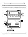
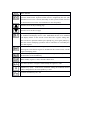
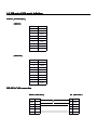
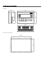
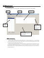
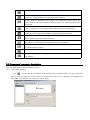
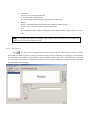
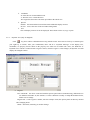
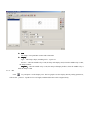
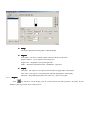
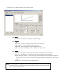
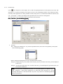
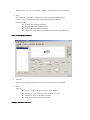
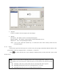
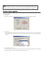
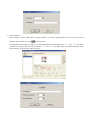
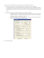
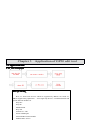
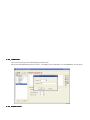
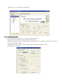
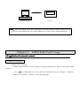
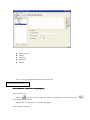
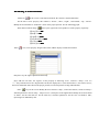
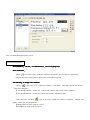
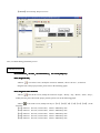
Electronic
MP series mini touch screen
Operate Manual
Xinje Electronic Co., Ltd.
Chapter 1
Summary
1-1. Function
MP330 is an operate panel with touch function. Via text and indicate lamp, monitor or modify the value and
status of PLC’s interior register and relay. In this way the operator can control the machine easily! It has OP series
operate panels’ all function, at the same time it support touch function!
MP330 has the advantages of following items
items:
� Via edit tool OP20, edit your program on your computer, you can input the letters and set PLC ID freely, use
COM ports to download the screens.
� The communication protocol will be downloaded to the model along with screen data, PLC needn’t compile
communication program.
� Can connect with nearly all PLCs popular in the current market, such as Mitsubishi FX series、Omron C series、
Siemens S7-200 series、Koyo SG series etc.
� With password protection function
� With alarm list function, real time display the current alarm information line by line.
� 26 function keys, each function key can be defined freely
� Add touch function which make control more easily
� Freely choose communication format, any one of RS232/RS422/RS485
� Add vector text and vector buttons which make the project screen more expressive
� With backlight STN LCD display, normally it can display 24 ASC×4 lines. If use the vector units, it can display
more information!
� The display’s surface is IP65 structure, water-proof, oil-proof
1-2General Specification
1. Electric Specification
Input Voltage
DC12V-DC24V
Power
Below 4W (TYP2.0W)
Momentary power cut allowance
Below 20ms
Voltage Endurance
AC1000V-10mA
Insulate impedance
DC500V-about 10MΩ (signal and time)
1 minute (signal and time)
2.Ambient Condition
Operate temperature
0~50℃
Store temperature
–10~60℃
Ambient humidity
20~85% (No dew)
Vibration endurance
10~25Hz (X,Y,Z each direction 2G per 30 minutes)
Anti-interfere
Voltage noise: 1000Vp-p
Ambient air
No canker gas
Protect structure
Fit IP65
1-3 Each part
part’’s name
Besides LCD display part on MP330
MP330’s front side, there are also 26 film buttons. Which give you nice touch feelings, also
have advantages of long life, safe and liability. The direction keys can rapidly turn to any screen and check the screen
status; the number keys can easily realize number input and modify. About the function keys, they not only have self’s
basic functions, the user can also freely define their functions when designing the project screens.
LCD
Function
keys
1
2
3
4
5
6
7
8
6
7
8
9
2
3
4
5
1
0
Number
keypad
Label
MODE:
SN:
DATE:
COM
port
XP3-18R
20060502118
20060510
无锡市信捷科技电子有限公司
Label
Terminals
1-4 Button
Button’’s basic function table
RS485
Button
Basic function
No matter what status the panel is, once press this key, it will return the
system’s initial screen. System’s initial screen is assigned by the user (the
defaulted screen is No.1 screen) Generally set the system’s initial screen to
be main menu screen or the screen which uses most frequently!
Turn the screen to the preceding page
Turn the screen to the next page
Press this key to modify the register’s value, the current register window to
be modified will display inverse color. Meanwhile the bit to be modified
will display flicker. If the current screen don’t have register setting unit,
then execute no operation. Before press [ENT] key, press again [SET] key,
then the current modifying operation will be cancelled. Go on modify the
next data register.
Write the modified data into the register, then continue to modify the next
data register. After the last register is modified in the current screen, exit the
register modifying status.
Alarm list key. After setting the alarm list function, press this key to shift to
the alarm list screen immediately.
When modify register’s value, clear the chosen area.
Set value’s positive or negative when modify the register’s value.
Number keys (0-9),in the status of number setting, the modified number
will be changed to be the correspond key’s value.
Common function keys F1~F8
1-5 MP series COM port
port’’s definition
download port
PORT1
PORT1(download
port)
[ MP330 ]
PIN ID
Definition
1
NC
2
RXD
3
TXD
4
NC
5
GND
6
NC
7
RTC
8
NC
9
NC
PIN ID
Definition
1
TD+
2
RXD
3
TXD
4
Vacant
5
GND
6
TD-
7
Vacant
8
RD-
9
RD+
[ MP330-S ]
DP-SYS-CAB connection
9PIN hole
DP210
DP210(9PIN
hole)
9PIN hole
PC
PC(9PIN
hole)
RXD
2
2
RXD
TXD
3
3
TXD
RTS
7
7
CTS
GND
5
5
GND
1-6 Dimension and installation
Dimension:
56.5
1
2
3
4
5
6
7
8
6
7
8
9
2
3
4
5
1
0
121
111
172
162
The hole size when installing:
113
164
Items to note when installing
installing:
1、The installation hole’s dimension should be fit, there should be certain space, shouldn’t be tight to
void damage the panel. Please refer to the following graph.
2、The fix screw shouldn’t be tight to avoid damage the panel.
3、The four fix screws should under equality pressure.
4、When installing, it’s better add airproof ring in the airproof groove.
Chapter 2
Edit tool OP20
2-1 Basic summary of OP20
OP20 is the edit tool for OP series operate panels. It is run under Windows98/NT. This edit tool is easy to learn,
convenient to use, and any language can be input and display.
2-1-1 The installation and un-installation of this edit tool
OP20 is green edit tool which needn’t to be installed. Copy the software folder offered by the supplier to your
disk, then execute OP20.EXE will be OK. When you need to uninstall, just delete this software folder. This edit
toll can work smoothly under Windows98/NT.
2-1-1-22 About the project and screen
To a product, all the screens the user compiled are saved in one project. The base factors of a project are screens.
Via designing each screen, realize some certain function, realize the jump among different screens freely. All the
screens together is the application project made by the designer.
2-1-1-33 The screen
screen’’s content
After click OP20.EXE, the user can new create or open the screen. Each screen can place text、indicate lamp、
switch、data display set window、jump key、bar graph、fold-line graph、bit graph、dynamic text etc. Screen jump
are freely between two screens. The operator can realize data monitor, parameter setting, switch control, alarm list
monitor etc.
2-12-1-44 Using flow of OP20
Basic using flow of OP20:
Run the panel
Download the screen
Save the project
Edit the screen
Choose PLC type
Choose panel type
Create or open a project
Open the edit tool
2-2 Edit environment
2-2-1 The main screen
After running OP20 edit tool, there will be a screen shown below in the center of the computer.
Menu
Tool Bar
Working area
Screen
manager
Unit bar, if not
choose
the
model, no units
will appear
Property setting
If not choose the model, this
bar is invisible.
Edit environment
environment:
In the top of the edit tool, there are menus and tool bar;In the left column, there are screen ID and
screen description, at the bottom of this column, there is two icons [New] and [delete], they are used
to create new screen or delete the current screen.
In the center of this edit tool, there is an edit area. There are light gray dots in the display area (can
be cancelled). When the designer place or move the components, refer to the near dot’s position,
this will make it easy to snap to grid. When the designer drag the component, the move distance is
the integer times of 4.
2-3 Component description
The following, we describe some keys and their functions
functions:
Keys
Functions
Create a new project
Open a saved project
Save the editing project
Cut the text in the display area
Copy the text in the display area
Paste the text in the display area
Create a new screen, it’s function is the same with [New]
Show the current screen’s attribution content
Copy a screen to another screen
Delete the current screen
Enter alarm list information, every piece of alarm information corresponds with a
middle relay
Assign the system’s initial screen. When the model is working, press this key to return
directly to the initial screen. Generally the screen is the main menu screen ot the screen
which used mostly; Set the system’s password; Set the alternate control register’s ID.
Set whole bureau function keys
Via computer’s RS232 port, download the edited project to MP330 model.
The following is the brief introduction of 13 components in the left
left:
Component
Function
Text, can input Chinese, English and some special signals.
Register, place data monitor window or data setting window (The object is PLC data
register)
Indicate lamp, show PLC’s interior middle relay’s ON/OFF status.
Function key, the 26 keys on MP330 can be all defined to be function keys. The
function key’s usage include screen jump and switch control etc.
Fold-line graph, in industrial control graph, some parameters change slowly, the
operator wants to know the parameter’s changing process, the fold-line graph is most
ideal format
Bar graph, bar graph is used to display analog parameter directly, such as flow ﹑
pressure﹑liquid level etc. Its height, width and direction can be assigned freely.
Bit graph, can display machine’s graph, this make the operator easy to understand, can
also display factory Logo, factory badge to prompt the products appearance.
Dynamic text, via dynamic text to display the machine’s status, this make the operator
easy to operate, improve the produce efficiency.
True type text (support all language), the size can be modified via the font regulation.
This make the screen display more information. (Effective to MP330).
Dynamic true type text (support all language). The function is the same with dynamic
text, add font modify property.
Data component, when this property is set ON, it supports touch function and input.
Victor touch key (support all language). The size can be modified, it also have indicate
lamp function.
2-5 Component
Component’’s property description
Here, we mainly describe unit part and property part.
2-5-1. Text (only for Englist)
Press
key, there will be a rectangle moving with the mouse. Confirm to place it via click your mouse’s
left key, click your right key to cancel. After you confirm, there will be a text “Message” in the display area.
Meanwhile, in the property area, its property will be shown.
�
�
�
Coordinate
X: show the text’s horizontal direction.
Y: show the text’s vertical direction.
The origin dot’s direction is the most up-left dot in the whole area.
Special
Double:the horizontal and vertical direction both double display in times.
Inverse:inverse the color of the text and its background.
Text
The real display content. Chinese and English can be displayed. This column can be cut, copy or
paste.
Note : To all units, they all have “coordinate” and “special” these two items. So in the following
chapter, we will not mention these two items.
2-5-2. True type text
Press
key, there will be a rectangle frame moving with your mouse! Confirm with your mouse’s left key,
cancel with your mouse’s right key. After your confirmation, there will be a “Message” in the display area. Meanwhile,
in the attribution area, display this text’s property. This component is similar with “Text”. The difference is, “True type
text” can modify the font and size. Meanwhile, the display area can also be modified by modifying the font. This brings
lots of flexibility for the designer.
�
�
�
Coordinate
X: show the text’s horizontal direction.
Y: show the text’s vertical direction.
The origin dot’s direction is the most up-left dot in the whole area.
Special
Double:the horizontal and vertical direction both double display in times.
Inverse:inverse the color of the text and its background.
Text
The real display content. all can be displayed. This column can be cut, copy or paste.
2-5-3. Dynamic Text (only for English)
Click
key, there will be a dashed frame moving with the mouse. Press mouse’s left key to confirm (press
your right key to cancel). After your confirmation, there will be a “Dynamic Message” in the display area,
meanwhile, it’s property will be shown in the property area. This icon is similar with “Text”, the difference is:
Dynamic text’s content is connected with a register. That is, when the register’s value changes, the dynamic text with
display the changed content!
�
Register
PLC station ID:the device connected with this operate panel. When communicating, different device
use different station ID. So, this station’s set value is different. Usually we adopt the defaulted value,
needn’t user to change.
Register ID:set the register’s number, take the example of D0, the operate panel can directly monitor
value changing in D0.
Mode:data mode, normally you needn’t change.
�
Display:add the display content directly in the content column. When D0 is 1, display “manual status”.
2-5-4. Dynamic True Type Text
Press
key, add a dynamic true type text. There will be a defaulted “Dynamic Text” in the display area.
Meanwhile, in the property area its property will be shown. Dynamic True Type Text is similar with Dynamic Text
Text,
the difference is: Dynamic True Type Text can change the font and display area while Dynamic Text cannot. This
makes the project more flexible to design.
2-5-5. Lamp
Press
key and place it in the display area. In the property area, you could see “Coil” and “Display” this
two items. The lamp is used frequently in the project, it can be used as status indication, alarm indication, message
indication etc.
�
Coil
The lamp’s correspond PLC station and coil number
� Display
Type:The lamp’s shape, including circle、square etc.
Positive:when the middle relay is ON, the lamp will display solid; when the middle relay is OFF,
the lamp is hollow.
Negative
Negative:when the middle relay is ON, the lamp will display hollow; when the middle relay is
OFF, the lamp is solid.
2-5-6. Bar
Click
key and place it in the display area. The bar graph is used to display directly analog parameters,
such as flux﹑pressure﹑liquid level etc. Its height, width and direction can be assigned freely.
�
Range
The values determines the bar graph’s width and height
�
Register
PLC station:the device’s address which connects with the operate panel
Register number:Use as sequence data storage area
Register No.:Bar graph’s correspond register ID
Mode:data format (include Decimal、HEX/BCD,signed etc)
�
Display
Full value:The register’s correspond value when the bar graph 100% scale display
Zero value:The register’s correspond value when the bar graph 0% scale display
Direction:Bar graph’s display direction, can be Up﹑down or left, right
2-5-7. Register
Click
key and place it in the display area. In a control system, the data operation is necessary. So this
“Register” place a great role in the control system!
�
Register
PLC station:the device connected with this panel. When communicate with different device, the station is
also different. Generally we adopt the defaulted value. The user needn’t change.
Register number:Set this register’s number. Take D0 as the example, the panel can directly monitor the
changing of value in D0.
When choose “Set”, then this register will also have set function, there will be also two items: Encrypt and
low (up) limit.
Encrypt: To improve the device’s safety, all the set parameters can be protected by the password. For the
password setting and modifying, please refer to the next chapter.
Up/Low limit:The designer can set Up/low limit, this will make the data which exceeds this limit invalid.
This could protect the device when input too large or too low data. For example, when set the up value as
9000, the low value as 0. Only when 0<the set value<9000, the set value could be written into PLC;or
else wait for the next valid value.
�
Display
Here, set the register’s display nits and decimal bit, at the same time choose the display mode.
Note
Note:
When activate the register’s “Set”, it means this component has not only monitor
function but also set function. At the same time, support “Touch” function make this
register function better performance in the project.
2-5-8. Trend
Click
key and place it in the display area. Set its property in the property area. In the industrial control
area, some parameters change slowly. The operator wants to know these parameter’s changing process within a
certain time. Choose the trend graph is the most idea format.
�
Range
These values determine the trend graph’s width and height.
�
Register
PLC station:The device’s address which connects with the panel
Register number:Used as sequence data storage area
Register ID:The trend graph’s correspond register address
Mode:data format (including Decimal、HEX/BCD,signed or not)
�
Display
Full Value:The register’s correspond value when the trend graph 100% scale display.
Zero value:The register’s correspond value when the trend graph 0% scale display.
Sample data (point number):From left to right, all the sample points the whole trend graph has.
The larger this value, the more detailed the trend graph changes (Meanwhile the time will be
longer)
Sample cycle:The time space of two sample points
Note
Note:One trend graph can only display one curve. If the project needs many curves, you could
create more screens, in each screen, add a trend graph. At the same time add screen jump
key to screen to different screen.
2-5-9. Function Key
Click
key and place it in the display area. Set the correspond parameters in the property area freely. The
function key is used most frequently in the project. It has a close relationship with the system function control.
Generally in the application, use along with the text units, lamp unit etc. It contains three different functions (Set
coil、screen jump、set data). According to the requirement, the user can choose among them.
The following, we give detailed descriptions about these three functions:
Set coil
see the following graph
First,
First,“Set
coil”(see
graph)
�
Function
Key:display the defaulted “F1” key, click the pull-down menu, choose the correspond key on the panel
(See the following graph)
Hand:Display the hand graph or not, the defaulted format is display.
Disappear:Display this key or not. When choose this key, the key’s function is the same, just not displayed
in the screen.
Encrypt:Need to input password or not. If choose this item, you should input the password before you
execute the set functions.
Note
Note:the function key with different function, its correspond parameter is different. Key、
hand 、 disappear 、 encrypt these parameters are valid with all the function keys. So the
following description, we will not introduce any more. Our point lies in introducing different
function’s parameters.
Function item:set coil、screen jump、set data;the defaulted is “Set coil” function
�
Coil
PLC station ID:The address of the device which is connected with the panel
Coil No.:PLC’s interior coil number correspond with this function key.
Function items:
� Set ON (the coil keep ON status)
� Set OFF (the coil keep OFF status)
� Inverse (the coil alternate working)
� Momentary ON (make the coil momentary activate a program cycle)
” function
Now, “screen jump
jump”
�
Function
If choose “Screen Jump” function, you could see in the property area changed.
�
Screen
Jump to:
�
�
�
�
Screen:Jump to the object screen’s screen number
Password:Jump to the password “open/close” screen
Alarm list:Jump to the alarm list screen
Data/Time: Jump to the time set screen
” function
Finally, “Set Data
Data”
�
Function
If choose “Set Data” item, the property area also changes.
�
Register
PLC station:The address of device connected with the panel
Register number:The sequence register number of data which needs to be set
Register No.:PLC’s correspond register address
Value : the set value, when this function key is executed, this value will be directly written into the
correspond register.
2-5-10. Picture
Pictures play a great role in the project. It is used in screen, flow, prompt, introduction and other function. The
general behave forms are company LOGO、art characters、art fonts etc.
Click
key, there will come out a “open” dialog box. Find the picture you want, then click “open” to add
into the screen.
Note
Note: There are some skills in using this picture unit. In project application, usually use some
picture dispose tools to edit the picture. Make the proper size and contrast, then add to the project
screen.
� Normally, to OP series operate panels, the size is not larger than 180×60 pixels
� Regarding LOGO pictures, the size is not larger than 35×35 pixels
� Regarding the pictures, the size is not larger than 60×60 pixels
2-5-11. Touch
Press
key and place it in the display area. Regarding usage, this unit is the same with the function key.
The difference is: this unit is a vector key. The font and size can be changed; it also support touch function.
�
�
Function (please refer to the function key)
Coil (please refer to the function key)
Skills
Skills:When using the touch key to design the screen, we know we could change the touch key’s size via
change the character’s size. However, the size changes with proportion (the height and width changes at
the same time). How to hold the height while change the width? We could add “space” to change.
2-6 System window
window’’s application
For OP series operate panel’s description, please refer to the manual of《OP series operate panel user manual》. Here we
mainly describe MP330.
� Select model
When create a new project, you should choose a model, here we choose MP330 (XMP) as our model.
�
PLC selection
After choosing the panel model, please choose the connection device (generally is PLC device). In the PLC column,
you could choose PLC model. If no your choice, you could also choose via other way (e.g. choose RS485) to
connect.
�
Set Communication parameters
Usually, user needn’t set this parameter. After choose your device (PLC), adopt your defaulted setting. According to
your defined setting, you could set according to the communication protocol.
�
Choose COM port
After finish editing your screen, you will download your screen to the panel, so you need to choose the COM port.
�
New create a screen
Open method: choose “Menu—Tool—New”; or directly choose “New”
;or click
in the tool bar.
Using method:According to your requirement, you could add screens freely. Each screen corresponds with a screen
number, it can only be changed when the screen is created. Screen description is used as a brief introduction or
prompt or Memo, you could also make no description.
�
Screen Attribute
Open method : Choose “Menu-Tool”-“Screen Attribute”; Or directly double-click the screen in the left screen
manage column; Or directly click
in the top menu.
Using method: In this property window, you could change the screen description. Key“∧” and “∨” are usually
used for screen jump. In the screen, if you add key“∧”or key“∨”,also make some correspond setting, then in the
screen property, these two keys will be of no use.
�
Alarm list
The alarm list plays a great role in one project. OP20 software integrate OP series、MP series、XP series abnormal
alarm system.
Open method: Choose “Menu-Tool”-“Alarm List”; or directly choose
in the tool bar.
Using method: In “Alarm Content”, input alarm information. Then, in “Coil” column, the correspond coil will appear.
These coils will be used to be drive coil of alarm information appear! The defaulted coil is M0. At the same time,
PLC station number and coil number will display brightly, it means they could be modified. See the following graph:
When running, if PLC interior coil M0 is ON status, then the textile display will show alarm screen, say
“temperature too high”. If M1 is ON status, the screen will show “level reaches”.
�
Set OP series
Open method: Choose “Menu-Tool”-“Set OP series”; Or choose
directly.
Using method: This part includes two small parts (see the following graph): OP Series Parameter、OP Series Control
OP Series Parameter:
� Master Screen ID: After the assigned project starts, display correspond screen’s set value. Usually defaulted
No.1 screen as the master screen;
� Password: To some projects which need to be protected, set password to manage the operation of different user;
� Screen Save: Set the screen protection modes. There are two modes: display screen and turn off backlight. The
user can set freely in the using process. If set “display screen”, choose a defined screen as the screen protection,
when time reaches, they system will automatic jump to this screen. If set as “turn off backlight”, then when the
time reaches, the system will automatic turn off the backlight. According to the requirement, modify the screen
save time. The defaulted time is 3 minutes, if set “never”, the backlight will light all along.
OP Series Control:
In the defaulted condition, PLC station and Register No. will display in gray. It means can’t be used. If choose any
item in “Interactive Control” or “Peripheral Control”, these two items will display brightly, it means they can be
modified! Via modify register No., modify the correspond register (If choose PLC type as Xinje XC series, the
defaulted register number is D0); Generally PLC station number use the defaulted value, needn’t change. Only if
many PLC online communication, then according to the actual requirement, modify this item.
� Interactive Control: Includes “Auto Change Display Screen” and “Report Current Screen Number”.
Auto Change Display Screen: This item corresponds with register D0. That is, if D0 is changed in PLC program,
then the display screen will jump to D0 value’s screen number. “Report Current Screen Number”, this item
correspond register D1, that is, if the screen refresh, value in D1 will refresh promptly to the current screen
number.
�
�
Peripheral Control: Includes “Analog Input/Output” and “Use Data/Time Module”.
“Analog Input/Output”: According to modules number (According to the actual project requirement,
defaulted one module. I.e. 8 channels, each module engrosses 2 registers.), they correspond a
continual register area from register D2 to register D17.
Use Data/Time Module: Correspond D18 register. I.e., the panel’s real-time clock information is
written into 6 continual register area from D18 register.
Set General Function Key
Open method: Choose “Menu-Tool”—“Set General Function Key”; or click
icon directly.
Using method: In the defaulted condition, all the function keys could be defined separately. If some function keys are
set as general function keys, then no matter which screen displayed, all response these keys and their defined general
functions. They are same with shortcut keys. This brings more flexibility to the project items. E.g.: set F1 as general
screen jump function key, see the following graph: set screen as 2, click “OK”, then no matter which is the current
screen, after press F1 key, the screen will jump to screen 2.
Chapter 3
Application of OP20 edit tool
3-1 Application flow
New create project
3-1-1
3-1-1.New
PLC type choosing
choosing:
Here, we listed some devices which are supported by MP330. We could see,
MP330 support most popular PLC、 some single-chip devices、self-defined models and
special function modules etc.
Xinje XC
Xinje FC
Mitsubishi FX
Koyo SG
Siemens S7-200
Omron CPM/CQM
Schneider Micro/Neza/Twindo
Modbus RTU(Slave)
Add Screens
3-1-2
3-1-2.Add
After create your project, the following thing is add screens.
The system will defaulted to generate screen 1, according to your requirement, you could add more screens freely.
Edit the screen
3-1-3
3-1-3.Edit
“Edit screen” is very important in a project design.
Set System Parameter
3-1-4
3-1-4.Set
Here, set master screen number as 1, i.e. set screen1 as the start screen.
If password is not necessary in the project, then set password as 0.
Defaulted screen protect time as 3 minutes. Here we modify the time as 15 minutes, meanwhile, set screen save
mode as “Turn Off Back-Light”.
To “Interactive Control”, here we needn’t setting, so adopt the defaulted setting (not choose).
After setting, save the project.
Recommendation
Recommendation:
In the design process, some in-expected accident may happen, such as power cut, operating system
problem, system break down or other accidents which cause close of edit tool, this will lead our projects
not saved. So, we suggest you often save the project.
建议:
在设计过程中难免会出现一些意外的情况,比如说断电、操作系统出问题、系统崩溃等其他因素导
致软件的关闭,这样使我们的劳动成果没有及时保存下来,带来很大的麻烦。
因此,大家在设计过程中,经常对所做的工作及时保存。这会是一个良好的习惯。
System Password
3-1-5
3-1-5.System
System password set the different operating limitation for different operator. To the whole project, this
measure places a great role for the safety and reliability. After setting the system password, the system will have
encrypt and open the password function. Only after you open the password could you use some protected
operations.
After set function keys and touch keys in the screen, in the function key’s property frame, choose “Screen
Jump” function, the screen will jump to “Password”.
In the “Password” screen, after input password, click “Open Password” key. If the password is correct, it will
prompt “Password Open”, then back to the operating screen; If password is wrong, then please input again or
cancel.
After executing the operation, please remember to close the password, or the system password will be in the
status of open. In this way, operator limited can also operate.
Download The Screen
3-1-6
3-1-6.Download
After finish designing the project, please download it into the panel. This is also the last step.
Connect the panel and the computer with a download cable, then click “Download” key.
COM PUTER
M P320
Note
Note:When downloading, please don’t cut the power to prevent the data not totally transferred to the
panel. Or system abnormal will occur. If this condition occurs, please connect and download again
Chapter 4
OP20 Edit Tool Usage
4-1Application of automatic control
Add and Set screen property
Modify screen 1 property:
Double click the screen 1 in screen manage area. In the pop out dialog box, add screen description “Master
Control”.
Click
key, add another four screens, add screen description one by one: “Monitor”, “Parameter”,
“Manual” and “Automatic”, “Manual”. See the following graph:
�
�
�
�
�
Master Control
Monitor
Parameter
Automatic
Manual
Here, we give some detailed information about each screen:
Edit The Master Control Screen
Screen Elements: a title, four screen jump keys
First, design the title:
Add one
icon in the screen, change the content as “Automation Control System”; click
key to modify the font and size.
Drag the title to a proper place, see the following graph.
Then, design the menu key:
Place four
keys in the screens, separately each text content and property: “Manual”, “Automatic”,
“Monitor” and Parameter”. Set each font.
Set each touch key’s function and parameter:
【Manual】Function: Screen jump; jump to screen 5
【Automatic】Function: Screen jump; jump to screen 4
【Monitor】Function: Screen jump; jump to screen 2
【Parameter】Function: Screen jump; jump to screen 3
Here, we finished editing [Master Control] screen.
Edit the Monitor Screen
Screen Elements: one title, nine textual description, six indicate lamps, one data monitor unit, one
dynamic indicate unit and one screen jump key
First, set the title:
Place one
key in the screen, change the value as “Monitor Screen”, Choose “Inverse”, click
key to modify it.
Drag the title to the proper place. ℃
The following, we set the left elements:
Add seven
in the screen, set the font and content, the content is “Status Indication”.
Set the left six texts’ property: The content is: “Power”, “Run”, “Light”, “Auto Wind”, “Up”, “Down”.
Modify the font and choose “Underline”. Place in the proper position. See the following graph:
Then add six indicate lamps
, place by the right of the correspond text. Set the property separately:
【Power】coil M0
【Run】coil M1
【Light】coil M10
【Auto Wind】coil M11
【Up】coil M12
【Down】coil M13
Add a
icon, set its property: Register ID is D10; add the display content shown below
then place it by the right of【Status Indication:】
Next, add two text units, one register, set the property as following: Text 1 content is “Temp.”, Text 2 is
“ ℃”,they both choose inverse. Register ID is D 100, the display bits is 4, the decimal bit is 1, also choose inverse,
the left are defaulted. Place them in the proper position, used as temperature testing and indication.
Place
keys in the screen. Modify the first content as “Stop”, set the font and size; Set the touch key’s
function parameters: Screen Jump;Jump to screen 1, then place in the right bottom. Modify the second content
as “Back”. Set the font and size. Set the touch key’s function parameters: Set the coil; Coil number: M51;
Operating item: Momentary ON.
Here, finish editing [Monitor] screen
Edit Parameter Screen
Screen Elements: a title, four text description, four unit description, four data setting units and one
screen jump key
First, design the title
title:
Add one
in the screen, modify the content as “Parameter”, choose “Inverse”, set the font.
Drag the title to the proper position, refer to the following graph.
Next, design the other elements:
Add four
icons, set the property and content: “ Frequency”, “Flow Setting”, “Temperature Setting”,
“Length Setting”; Modify the font. Please refer to the following graph:
Add four “Register” icons, set separately their properties: Register ID separately are: D 500、D 502、D504、
D508;Digit is 4; Decimal is 1; At the same time choose【Set】, the left are defaulted; Place them in the proper
position
Then, add four
icons in the screen, set the content as “Hz”, “%”, “℃”, “m”; modify the font, place
them in the proper position, see the following graph:
Add one
icon in the screen, modify the content as “Back”, set the font; set its functions as screen
jump, jump to screen 1, then place in the right bottom.
Here, we finish editing [Parameter] screen.
Edit Automatic Screen
one title
two function keys
two screen jump keys
Screen Element
Element:one
title、two
keys、two
First, set the title
title:
Add an
icon in the screen, modify the content as “Automatic”, choose “Inverse”; Set the font.
Drag this title to the proper position, please refer to the following graph:
The following, we design other elements:
Add two
icons in the screen, modify the content as “ Auto Start”, “Auto Stop”; Set the font and size,
then set the functions:
【Auto Start】Function:Set the coil;Coil No. M2; Choose “Force ON”, Choose “Indicate”.
【Auto Stop】Function:Set the coil; Coil No. M3; Choose “Momentary ON”
At the same time, add three
icons in the screen, modify the content as “Monitor”, “Manual” and
“Back”, Set the font; Set the functions:
【Monitor】Screen Jump; Jump to screen 2
【Back】Screen Jump; Jump to screen 1
【Manual】Screen Jump, Jump to screen 5
Here, we finish editing [Automatic] screen.
Edit Manual Screen
one title
two function keys
two screen jump keys
Screen Elements
Elements:one
title、two
keys、two
First, design the title
title:
Add one
icon in the screen, modify the content as “Manual”, choose “Inverse”, set the font.
Drag the title to the proper position, please refer to the following graph:
Next, design the other elements:
Add six
icons in the screen, modify the content as “Light”, “Pump”, “Up”, “Down”, “Start”, “Stop”;
modify the font, place them in the proper position, please refer to the following graph:
Add six
icons in the screen, modify each key as:【 F1】、【 F2】、【 F3】、【 F4】、【 F5】、【 F6】, set the
functions:
【F1】Function:Set Coil, Coil No. M21;Choose “Momentary ON”.
【F2】Function:Set Coil, Coil No. M22;Choose “Momentary ON”.
【F3】Function:Set Coil, Coil No. M23;Choose “Momentary ON”.
【F4】Function:Set Coil, Coil No. M24;Choose “Momentary ON”.
【F5】Function:Set Coil, Coil No. M25;Choose “Momentary ON”.
【F6】Function:Set Coil, Coil No. M26;Choose “Momentary ON”.
Finally, add six
keys in the screen, modify the content separately as “Monitor”, “Back”, “Automatic”,
“Power”, “Stop”; set the font and functions:
【Monitor】Screen Jump; Jump to screen 2
【Back】Screen Jump; Jump to screen 1
【Manual】Screen Jump; Jump to screen 4
【Power】Set Coil; Coil No.:M50;Choose “Inverse”
【Stop】Set Coil; Coil No.:M51;Choose “Momentary ON”
Here, we finish editing [Manual] screen.