1
US006231560B1
(12) United States Patent
(10) Patent N0.:
(45) Date of Patent:
Bui et al.
(54)
May 15, 2001
“Block Medical: Growing With Home Infusion Therapy,”
taken from Invivo, The Business and Medicine Report, Apr.,
1991; pp. 7—9.
“IEEE—488 and VXIbus Control, Data Acquisition, and
METHOD AND APPARATUS FOR
AUTOMATICALLY CONTROLLING THE
LEVEL OF MEDICATION
(75) Inventors: Tuan Bui, Green Oaks; D0r0n Levitas,
Analysis . . . the Most Choices,” select pages taken from
Chicago; Stephen L. Axel, Deer?eld,
National Instruments, Application Software Products and
all of IL (US)
Application Software Overview, (1991) 17 pages.
“LabView®2 User Manual; Chapter 2, The Front Panel,”
taken from National Instruments Corporation, Jan., 1990;
(73) Assignee: Baxter International Inc, Deer?eld, IL
(Us)
Notice:
US 6,231,560 B1
pp. 1—36.
J. C. Crone, Jaromir Belic and Roger W. Jelliffe, M.D., “A
Programmable Infusion Pump Controller,” taken from 30th
Subject to any disclaimer, the term of this
patent is extended or adjusted under 35
Annual Conference on Engineering in Medicine and Biol
U.S.C. 154(b) by 0 days.
ogy, Nov. 5—9, 1977; pp. A—35827 through A—35837.
Selective portions of Chapter 9 of Mayhew, “Principles and
(21) Appl. No.: 09/248,492
Feb. 10, 1999
(22) Filed:
(51) Int. Cl.7 .................................................. .. A61M 25/00
(52) US. Cl. ........................... .. 604/500; 604/503; 604/66
(58) Field of Search ................................ .. 604/65, 66, 67,
Guidelines In Software User Interface Design,” Prentice
Hall PTR, Englewood Cliffs, New Jerssey, 1992.
Electronic’s Article of Feb., 1990, by Jack Shandle, entitled
“Who Will Dominate the Desktop in the ’90s,” pp. 48—50.
Chapter 5 entitled “Direct Manipulation” from Shneiderman
“Designing the User Interface: Strategies for Effective
Human—Computer Interaction,” Addison—Wesley Publish
604/30, 31, 131, 151, 500, 503; 417/2,
ing Company, Second Edition, @1992, reprinted with cor
53, 63
rections 1993.
Literature of Baxter’s MultiPlexTM Series 100 Fluid Man
agement System, 2 pp., no date listed.
References Cited
(56)
U.S. PATENT DOCUMENTS
3,739,943
3,858,574
6/1973
1/1975
Literature of Baxter “Introducing MultiPlexTM Series 100
Fluid Management System,” copyright 1988.
Wilhelmson et a1. ............... .. 222/59
Page ............................... .. 128/205T
Literature describing Baxter’s Flo—Gard® 6201 Volumetric
Infusion Pump, copyright 1992.
(List continued on next page.)
(List continued on next page.)
FOREIGN PATENT DOCUMENTS
WO 98/19734
Primary Examiner—John D. Yasko
(74) Attorney, Agent, or Firm—Wallenstein & Wagner, Ltd.
5/1998 (WO) .
OTHER PUBLICATIONS
(57)
ABSTRACT
A.H. McMorris, J .L. Kelleway, B. Tapadia and E. L. Dohm
A method and apparatus which captures relevant informa
tion pertaining to a patient’s physiological conditions, auto
matically adjusts the amount of medication to optimize the
ann, “Are Process Control Rooms Obsolete?”, taken from
Control Engineering, pp. 42—47, Jul., 1971.
Abbott Laboratories, The Blue Line System, Lifecare, copy
right, 1990.
LC. Sheppard, “Computer Based Clinical Systems: Auto
mation and Integration,” taken from 39th ACEMB, Sep.
13—16, 1986; pp. 73—75.
treatment of pain and improve the patient’s quality of life is
described.
18 Claims, 7 Drawing Sheets
M
264
num
LEIIS
mm
um
mu m:
mun
04
US 6,231,560 B1
Page 2
US. PATENT DOCUMENTS
3,910,257
10/1975
4,173,971
11/1979 KarZ ................................... .. 128/702
4,392,849
4,413,314
4,449,538
4,531,527
Fletcher er a1- ----------------- -- 128/2-1A
7/1983 P999 er 9111/1983 Slater et al. ....................... .. 364/188
5/1984 Corbin er a1
7/1985 Reinhold, Jr. et al.
4,551,133
11/1985 Zegeers d9 Beyl 9t 91- -
4,561,443
12/1985
4,586,260
Hogrefe er a1- ----- --
11/1986 Arimond
6/1987 H9ws9n ---- -
4,696,671
9/1987 Epstem er al-
4,731,051
3/1988 Flschell
4,756,706
7/1988 Kerns er a1-
4,797,840
1/1989 Fraden
4,803,625
2/1989 F11 er a1
4,810,243
4,828,545
3/1989 Howson .... ..
5/1989 Epstein et al. .
4,850,972
7/1989
4,865,584
9/1989 Epstein et al.
schulman er a1- -
5/1994 Coutré et al. ...................... .. 364/413
8/1994 Blomquist .............................. .. 417/2
11/1994 Hall et al. .......................... .. 128/633
573687562
11/1994 nlomquist et a1
5,376,070
12/1994 Pun/is et al
5378231
604/65
604/31
1/1995 Johnson et a1 _
604/67
-- 128/760
5,395,321
3/1995 Kawahara e161.
604/67
128/696
5395329
3/1995 Fleitschhackor et at
604/95
5,400,246
3/1995 Wilson et al. ....... ..
. 364/146
-- 128/419 PG
5,412,400
5/1995
6/1995 Uhala _
5/1986 Baxter et al. ..
4,624,661
4,676,776
5,317,506
5,338,157
5,361,758
33/125 C
574237748
-- 604/151
604/31
5,429,602
5,469,855
Takahara et al. .................. .. 345/119
7/1995 Hauser ................................. .. 604/65
11/1995 Pompeietal. ..
. 128/664
604/67
5,482,446
1/1996 Williamson et al.
- 606/67
5,485,408
1/1996 Blomquist
604/66
5,509,422
4/1996 Fukami ..... ..
. 128/670
-- 364/557
5,522,396
6/1996 Langeretal.
. 128/696
364/413-03
5,544,651
8/1996
. 128/633
604/31
604/66
575587638
5573506
9/1996 Evers et at
11/1996 Vasko
-- 604/151
5,582,593
12/1996
604/67
576437212
-- 364/200
417/474
. 364/578
Wilk .......... ..
604/66
604/65
Hultman
.................. .. 604/65
7/1997 Coutré et at _
4,901,221
2/1990 Kodosky 9t 91-
4,925,444
5/1990 Orkm 9t a1~
4,933,843
6/1990 Scheller 9t 91-
4,942,514
4,952,928
4,995,268
7/1990 Miyagaki et al. .
364/190
8/1990 Carroll et al. .
340/825.54
2/1991 Ash et al. ....................... .. 73/861.05
5,002,055
3/1991
5,038,800
8/1991 Oba .................................... .. 128/904
Llterature 0f I—F10W Corporation advertising its Vivus 4000
5,069,668
5,078,683
12/1991 Boydman .
1/1992 Sancoff et al. ....................... .. 604/67
Infusion System.
One_page article by Jerry Hirsch entitled “Portable IV Frees
Merki et al. .
3/1992 EPSteln ct a1~ -
604/67
5/1992 Goodman e161
.. 128/633
5 115 133
5/1992 Kn d
5,116,312
5/1992 Blankenship et al. ............... .. 604/66
,
5,137,023
u
son
............................ ..
250/341
.. 604/66X
5,935,099 *
8/1999 Peterson e161. ..................... .. 604/65
670107483
H2000 Spencer _
OTHER PUBLICATIONS
_
571007380
............... .. 604/151
5,840,026 * 11/1998 Uber, III et al.
364/413-01
5,109,849
,
5,681,285 * 10/1997 Ford et al.
604/80
_
_
_
_
_
Patients,” printed in The Orange County Register, D section,
NOV‘ 21’ 1991'
“
.
.
Be‘ider’ et a1“ C0,,“ Analylslsfof ,TWO {implantable Narconc
5,152,296
5,153,827
8/1992 Mendelson et al. ..
.. 128/633
10/1992 Simons .............................. .. 128/670
10/1992 Coutré et al. ................. .. 364/413.02
De lvery Systems> Jouma 0 Palm an Symptom Manage‘
ment, V01- 6, NO- 6>A1lg-> 1991, PP- 368—373
Peter Lord, Hossein Allami, Mark Davis, Raul Dias, Patrice
5,155,693
10/1992 Altmayer et al.
364/550
Heck, and Robert Fischell, pp. 66—71 from book chapter
5,165,874
11/1992 Sancoff et al. ..................... .. 417/474
entitled “MiniMed Technologies Programmable Implantable
Seacord et al. .................... .
5,191,891
3/1993 Righter ...... ..
5,207,642
5/1993 Orkln et al. ......................... .. 604/65
5,213,099
5/1993
572267425
7/1993 Righter
5,230,623
5,256,157
5,291,190
.. 128/710
rrIMED®StamsTM
Infusion System,” describing
Infusion Management
Clinical trials System,”
from NOV‘,6 page
brochure IMED CO
Tripp, Jr. ............................ .. 128/633
__ 128/710
7/1993 Guthrie et al. ....................... .. 433/72
10/1993 Samiotes et al. .................. .. 604/246
3/1994 Scarola et al. .
340/825.06
5,295,062
3/1994
5,297,554
3/1994 Glynn et al. ....................... .. 128/665
’
James
oration San Die 0 CA no datehsted
rp
_ ’
g
’
'
Foley and Andries Van Dam Fundamentals of
Interac?ve Computer Graph1Cs,”s919Ct9d pages from Chap
ters 1 and 2, Addison—Wesley Publishing Company, @1982,
reprinted With corrections 1983,
Fukushima ......................... .. 364/188
* cited by examiner
U.S. Patent
May 15, 2001
78
US 6,231,560 B1
Sheet 1 0f 7
70
12
42
43
54
g®@ ®@ hw m
15
17
11
10
l7—— PATIENT j
13
L9.
U.S. Patent
May 15, 2001
US 6,231,560 B1
Sheet 2 0f 7
236
'-—————> AMP é—————>®'\51
230
5
;
264
ALARM
e20
21(2/_
234
LEDS A
A222
‘
220
ZGOL wATcl-mm;
BACKLIGHT f
232
DISPLAY
250
4 I 252 262
CONTROLLER
1
16
E
AID
~2OOA
276
<./ 270 {2'74
L L 6’ L'
2L72 L '"
300
sw
m"
308
C Am
D
K
E3,02K
K’ ['[c
EASISSEER ?
%
8w
'2312
320
HALL
seuson
4
304
sw
r‘
31/0
V/R — sw
3/80 290
288
L/
ONIOFF
28(2- BA"
294
/ 330
CASSETTE
season
1 8 34E“
a.‘ [_ 5W
4325 sgggn
‘
i
h32
IIO INTERFACE
'
EPRDM
RAM
DOOR
332
g
K V 9
N
l/LA
31 4
<
Bows
‘ ‘1%
KEYPAD
29A
r208
1 RS232
221
214
S
BATT
‘——'\
HEALTIME
_-_|/
CLOCK
N21 0
Fig.2.
U.S. Patent
May 15,2001
Sheet 3 0f 7
US 6,231,560 B1
400
j
3
mnmuzmou a. SELFT EST
F
J 404
ANY REMAINING VOL on TIME?
412
YES
406
no F
"0
LOCKOUT MODE?
41 4
YES
YES
"0
PROGRAMMABLE?
_)
YES
N0
420
RESUME?
YES
on LOCKOUT SEQUENCE
N0
424
YES
\
\
PROGRAM
commuous
PROGRAM
AUTO-RAMP
N0
428
YES
N0
432
\
PROGRAM
INTERMITTENT
YES
436
YES
\
\
PROGRAM
2s PERIODS
PROGRAM
PCA
j+ H
464
\
4101/
F REPORT ALARMS
F29. 3.
READY TO+RUN
RUN MODE
/
466
TURN OFF
U.S. Patent
May 15,2001
Sheet 4 0f 7
500
US 6,231,560 B1
OPERATING SYSTEM
02
RUN MODE?
510
YES
STEALTH MODE?
550
51?
504
/
"0
PERFORM
PROCESSING
TASKS
WITHIN 30
MINUTES OF NEXT
DOSE?
PERFORM
PROCESSING
TASKS
514
\
STROBE WATCI'IDOG
YES
EVEN 1o
51 6
MINUTES?
YES
'
5/06
IDLE MODE
1
SET
AUDIO
5/20
TURN OFF POWER TO SENSORS
BEEPS
I————\
l _
522V
5244/
F29 4|
sLEEP MODE
START CLOCKS
—’
WAIT FOR INTERRUPT
U.S. Patent
May 15, 2001
RUN
MODE
Sheet 5 0f 7
US 6,231,560 B1
/460
180
PATIENT
INITIATED
REQUEST
MODIFY
PCA
ROUTINE
I
QUERY
PATIENT
PCA
TIMER
EXPIRED
Y
OBTAIN
HISTORICAL
DATA
RESET
PCA
TIMER
I
PROCESS
DATA
l
MODIFY
PCA
Fig. 5.
U.S. Patent
May 15,2001
Sheet 6 6f 7
US 6,231,560 B1
PAIN INTENSITY SCALES
F29 6
SIMPLE DESCRIPTIVE PAIN INTENSITY sun1
I
I
l
I
I
I
r
|
I
I
I
J
1
N0
MILD
MODERATE
SEVERE
VERY
WORST >
PAIN
PAIN
PAIN
PAIN
SEVERE
PAIN
POSSIBLE
PAIN
0-10 NUMERIC PAIN INTENSITY scALE1
I
I
l
I
I
I
I
I
I
I
0
N0
1
2
3
4
PAIN
L
l
I
I
l
l
I
I
l
l
l
A]
I
5
6
MODERATE
7
a
9
10
WORST
PAIN
POSSIBLE
PAIN
VISUAL ANALOG scALE (IIAs)2
I
I
No
I
PAIN AS BAD
As IT COULD
POSSIBLE BE
PAIN
1IF USED AS A GRAPHIC RATING SCALE, A 10 CM BASELINE IS RECOMMENDED.
2A‘lIT-CM BASELINE IS RECOMMENDED FOR VAS SCALES.
SOURCE: ACUTE PAIN MANAGEMENT GUIDELINE PANEL, 1992.
436
SELECT 5
PCA PROFILE
‘
702
PROGRAM
5
PATIENT PcA ALGORITHM
‘I
704
SET
INITIAL BASAL RATE
F19. 7.
1,
SET
INITIAL BOLUS AMOUNT
I
STORE
" nATA
I RETURN
706
714
716
'
U.S. Patent
May 15,2001
Sheet 7 0f 7
US 6,231,560 B1
530
532
"s
534
OFF?
536
YES
MODE
538
TURN POWER OFF
540
STEALTH MODE
j
l F
L98.
US 6,231,560 B1
1
2
METHOD AND APPARATUS FOR
AUTOMATICALLY CONTROLLING THE
LEVEL OF MEDICATION
reduce pain suf?ciently to enable the patient to move about.
Using a level of pain medication Which produces confusion
detracts from the patient’s mobility.
During acute care, When the patient is in greater need of
additional pain medication, it is important to be able to
adjust the PCA basal rate, the bolus rate and the bolus
amount more frequently, alWays taking into account the
effect of side effects and impairment of patient functional
BACKGROUND OF THE INVENTION
The present invention is directed to a method and appa
ratus for automatically adjusting the medication level for a
patient, and more particularly to adjusting the basal rate and
the bolus rate of administration in a patient control analgesia
Infusion pumps are used to automatically administer
ities.
Infusion modes are programmed into the infusion pump
by the caregiver or physician. In a hospital or other caregiver
liquid medicants to patients. The liquid medicant is supplied
facility, a physician or caregiver can visit a patient once or
from a source of medicant and delivered to the patient via a
catheter or other injection device. The manner in Which the
tWice a day to check if the programmed infusion mode, dose
and frequency are providing appropriate relief to the patient.
If the patient is receiving medication at home or aWay from
a caregiver facility, such visits may be less frequent. In most
mode based on the patient’s pain intensity.
liquid medicant is infused is controlled by the infusion
10
15
pump, Which may have various modes of infusion. An
infusion pump typically can operate in ?ve basic modes of
infusion: 1) a continuous mode in Which the pump delivers
a single volume at a single rate; 2) an auto-ramp mode in
Which the pump delivers liquid medicant at a rate that
gradually increases to a threshold rate, remains at the
threshold rate for a period of time, and then gradually
decreases; 3) an intermittent mode in Which the pump
delivers discrete liquid volumes spaced over relatively long
periods of time, such as a liquid volume every three hours;
of the pre-programmed modes, rechecking the mode, dose
and frequency once or tWice a day may be suf?cient. If the
patient is in the PCA mode, hoWever, the patient’s condition
may vary more, requiring more frequent adjustment and
more frequent visits by the physician or caregiver. If the
patient is not able to receive additional adjustments or visits
from the physician or caregiver, Whether in the home or the
25
4) a custom mode in Which the pump can be programmed to
deliver a unique infusion rate during each of 25 different
hospital, the patient may be in extreme pain and may not
receive appropriate pain relief for many hours.
U.S. Pat. No. 5,643,212 to Coutre et al. discloses an
infusion pump management system in Which the patient’s
physiological signs are used in a biofeedback loop. The
time periods; and 5) a pain controlled analgesic (PCA) mode
during Which the pump Will periodically infuse boluses of an
system evaluates the patient’s physiological signs and sug
analgesic in response to requests by the patient.
gests alternate infusion treatment based on those signs. The
proposed modi?cations are then sent to the operator for
con?rmation. Delivery rate changes are made by the opera
tor (physician or caregiver), so the patient must Wait until the
In pain control analgesia, a pain relief medication or
analgesic is delivered to the patient via an infusion pump
into a patient’s intravenous line, or to the epidural space or
an interthecal space. Usually the medication is delivered at
a constant rate, called the basal rate. The physician programs
the basal rate into the pump. HoWever, the patient is alloWed,
Within bounds, to give himself additional medication, to
reduce the pain level, if desired. This is done via a bolus
cord. The patient presses a button on the bolus cord and the
pump delivers a small bolus of medication to the patient. The
maXimum level of medication given in response to each
press of the bolus cord button, is programmed into the pump
35
operator can evaluate the proposed changes before the
patient can receive any relief.
There is a need for an automatic method of adjusting the
medication level in patient control analgesia taking into
account the patient’s pain level, side effects and any impair
ment of functionalities. There is a need for an apparatus for
automatically adjusting the medication level in response to
input from a patient regarding his pain level, side effects and
impairment of functionalities, Without having to contact the
by the physician. The maXimum number of button presses
caregiver or physician. There is a need for a method of
grammed into the pump by the physician. Once the pump is
automatically adjusting the medication level in patient con
trol analgesia using a predetermined set of criteria Which is
programmed by the physician, the patient can give himself
patient speci?c, yet provides the patient the ability to have
Which Will result in a discharge of a bolus is also pro
45
a bolus Whenever he needs it, regardless of time betWeen
his medication adjusted Without having to contact a car
requests. HoWever, if the patient exceeds the maXimum
number of boluses programmed, any additional requested
egiver or physician.
SUMMARY OF THE INVENTION
boluses Will not be successful and Will not result in the
delivery of medication.
A preferred embodiment of the invention is directed to a
The physician limits the amount of medication given to
method and apparatus Which captures relevant information
the patient at any one time, and over a period of time, to
pertaining to pain level, side effects and patient impairment
reduce the level of side effects. Some pain relief medications
have highly undesirable side effects, such as nausea,
55
vomiting, itching and confusion, cardiac and respiratory
depression or in suf?cient quantity, may result in death.
Patient functionality, e.g., mobility and aWareness, is
Prior to prescribing pain medication to be provided via a
programmable infusion pump, the physician or caregiver
must program the pump for the speci?c patient. In addition
to programming in the speci?cs of a PCA treatment, by
programming in basal rate, maXimum number of bolus doses
affected by pain and side effects.
Controlling of the amount of pain medication, i.e., the
basal rate, the bolus dose and the maXimum number of bolus
doses available to the patient is a delicate balance of
competing requirements. To increase pain relief, a physician
Will prescribe greater medication. HoWever, large doses of
some pain medication can increase the side effects and can
impair patient functionalities. Using a pain medication may
and automatically adjusts the amount of medication, Within
a pre-determined level selected by the patient’s physician, to
optimiZe the treatment of pain and improve the patient’s
quality of life.
and volume amount of each bolus dose, in accordance With
65
the preferred embodiment of the invention, the program
mable infusion pump includes a routine for modifying the
PCA treatment. The PCA modi?cation routine stores pre
US 6,231,560 B1
4
3
programmed values of basal rate, bolus number and amounts
FIG. 8 is a ?oWchart of the operation of an on-off control
for the speci?c patient, Which are input the by physician or
caregiver. The routine also includes a pain relief algorithm
routine of the infusion pump shoWn in FIG. 1;
DETAILED DESCRIPTION OF A PREFERRED
EMBODIMENT
Which modi?es the PCA treatment in response to input
regarding the patient’s pain level, side effects and function
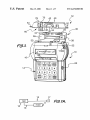
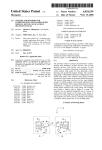
Referring noW to the draWings and speci?cally to FIGS.
1 and 1A, a portable infusion pump embodying the present
invention is shoWn therein and generally identi?ed by ref
erence numeral 10. The infusion pump 10 provides liquid
medicant to patient 11 via catheter 13. Bolus cord 15 is
impairment.
Pain level can be determined using either of tWo methods,
or by a combination of the tWo methods. In a ?rst method,
the programmable infusion pump stores the number of bolus
requests by the patient and Whether or not they resulted in
10
connected to pump 10. Patient 11 makes a bolus request by
delivery of a bolus over a prescribed period of time. If the
patient makes a signi?cant number of bolus requests over
pressing bolus button 17. A signal from bolus button 17
the maximum permitted in a short period of time, this is used
as an indication that the patient’s pain level is high. Asecond
method of determining pain level is to query the patient
directly and evaluate the patient’s responses. Acombination
332 (see FIG. 2) Where the request is processed by controller
200 (see FIG. 2).
travels doWn bolus cord 15 to bolus infusion request sWitch
15
The infusion pump 10 provides automatic adjustment of
a patient’s pain medication. A cassette 12 is insertable into
the pump 10. The portable pump 10 may be carried in a
pouch or other device (not shoWn) attached to a patient so
that the pump 10 may be carried Wherever the patient goes.
of both methods can also be used.
Side effect information can be determined in either of tWo
Ways, or by using a combination of the tWo. In the ?rst
method, the patient is asked various questions about speci?c
The infusion pump 10 has a keypad 14 via Which a user
side effects. In a second method, if the patient is in a hospital
or other facility With a caregiver, the caregiver records the
patient’s responses to inquiries about side effects on the
may input data and commands, a selectively backlighted, dot
patient’s chart. The caregiver may also record his observa
tions about the patient’s side effects onto the patient’s chart.
matrix or LCD display 16 for displaying textual messages to
the user, a light sensor 18 for detecting the level of ambient
25
a red LED for indicating an alarm or abnormal operating
Data recorded on the patient’s chart can later be input to the
programmable infusion pump. A combination of both meth
condition of the pump 10. As described beloW, the level of
the light sensed by the ambient light sensor 18 is used to
ods can also be used.
control When the display 16 is backlighted. A data port 22,
Similarly, information regarding impairment of patient
Which is preferably an RS-232 port, is used to doWnload and
upload data betWeen the pump 10 and a remote controller or
functionality can be input by the patient in response to
speci?c queries prompted by the infusion pump, or by a
other device. Data port 22 Would be used to upload vital sign
data from a vital sign monitor, such as heart rate, respiration
caregiver or by a combination of both.
After completion of inputting all data, the data is pro
cessed by the algorithm, and the patient’s PCA medication
rate is conformed to the algorithm or adjusted if indicated by
rate, for example.
35
the algorithm.
In an alternative embodiment of the invention, if the
patient’s vital signs are being monitored, they can be used to
provide data regarding the side effects and patient function
alities. Vital sign data can be input to the programmable
infusion pump via a data port, processed by the algorithm
and the patient’s PCA medication adjusted.
These and other features and advantages of the present
invention Will be apparent to those of ordinary skill in the art
in vieW of the detailed description of the preferred
embodiment, Which is made With reference to the draWings,
a brief description of Which is provided beloW.
An arcuate metal leaf spring 36 is disposed on the
underside of the door 30. The tWo ends 37 of the leaf spring
36 are anchored by a pair of retaining elements 38 ?xed to
the door 30. When the cassette 12, in Which a ?exible
silicone tube 40 is disposed, is inserted into the pump 10 and
the door 30 is closed, the leaf spring 36 makes contact With
and applies a doWnWard force on an upper surface 42 of a
vertically movable platen 44. As shoWn in FIG. 1, the upper
surface 42 of the platen 44 is disposed Within an elongated
slot or aperture 43 disposed in the upper surface of the
cassette housing 12. The platen 44 has a loWer curved
surface 46 against Which the ?exible tube 40 is pressed by
a number of rollers disposed on a conventional rotary pump
55
The cassette 12 has a ?oW-stop mechanism 60 that
automatically clamps the ?exible tube 40 shut When the
cassette 12 is not disposed in the pump 10 With the silicone
tube 40 in its fully engaged position or When the pump door
30 is open. This prevents an open or uncontrolled liquid path
being made available betWeen the medicant source and the
patient. The ?oW-stop mechanism 60 has a housing 62.
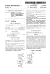
FIG. 6 shoWs sample pain intensity scales suggested by
FIG. 7 is a ?oWchart of the operation of the program PCA
mode of the infusion pump shoWn in FIG. 1; and
Wheel (not shoWn) to effect peristaltic pumping of liquid
through the tube 40.
programming of the infusion pump shoWn in FIG. 1;
the Acute Pain Management Guideline Panel;
A door 30 is pivotally attached to the upper portion of the
infusion pump 10 via a plurality of hinges 32. An underside
33 of the door 30, Which is shoWn in FIG. 1, has a pair of
slots 34 formed therein in Which a pair of metal rods 35 are
?xed. Each of the metal rods 35 selectively engages a pair
of slidable latching members (not shoWn) to retain the door
30 in the closed position during operation of the pump 10.
BRIEF DESCRIPTION OF THE DRAWINGS
FIG. 1 is a perspective vieW of an infusion pump embody
ing the present invention and a cassette Which is insertable
into the pump;
FIG. 1A is a block diagram shoWing the connection of the
infusion pump of FIG. 1 to a patient;
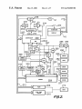
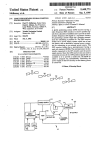
FIG. 2 is a block diagram of the electronic and electrical
components of the infusion pump shoWn in FIG. 1;
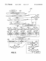
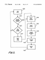
FIG. 3 is a ?oWchart of the overall operation of the
infusion pump shoWn in FIG. 1;
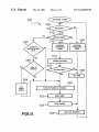
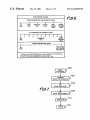
FIG. 4 is a ?oWchart of the operating system used by the
infusion pump shoWn in FIG. 1;
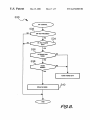
FIG. 5 is a ?oWchart of the operation to modify the PCA
light, and a pair of light-emitting diodes (LED) 20, a green
LED for indicating the normal operation of the pump 10 and
65
Infusion Pump Electronics
Referring to FIG. 2, the infusion pump 10 includes a
controller 200 With a built-in analog-to-digital
con
US 6,231,560 B1
5
6
verter 200A, an electrically programmable read-only
memory (EPROM) 204 having a built-in input/output (I/O)
The pump 10 has a shaft encoder sensor 308 and a
Hall-effect sensor 310 Which receive poWer from a poWer
interface 204A, a random-access memory
sWitch 312 coupled to the system poWer line 287 and
controlled by the controller 200 via a line 314. The shaft
encoder sensor 308, Which is disposed on the shaft of the
motor 51, may be a tWo-phase motion sensing encoder
Which provides tWo signal outputs to the controller 200. The
rotational speed of the motor 51 and its direction of rotation
are determined by the controller 200 based upon the rate and
208, a
real-time clock 210 and the display 16, all of Which are
interconnected by a communications bus 212. The display
16 has a backlight 220 Which is selectively activated by an
enable signal generated on a line 222 interconnecting the
controller 200 and the backlight 220. Both the RAM 208 and
the real-time clock 210 are connected to a battery 214 Which
supplies poWer to them only in the absence of system poWer
phase relationship betWeen the tWo signal outputs. The
(generated by a second battery 282). Since it is alWays
poWered, the RAM 208 is a non-volatile memory.
The controller 200, Which may be a conventional micro
controller such as an 80C196KB commercially available
from Intel Corporation, controls an audible alarm generator
230 via a line 232, the LED’s 20 via a line 234, and a pump
motor signal ampli?er circuit 236 via a line 238. The pump
motor signal ampli?er circuit 236 is connected to drive the
pump motor 51 Which drives the rotary pump Wheel. During
normal operation, the controller 200 also sends a periodic
signal to a conventional Watchdog timer 250 via a line 252.
If the controller 200 should fail to transmit the periodic
15
Hall-effect sensor 310 is disposed adjacent the rotary pump
Wheel and detects magnetic encoding on the pump Wheel for
detecting rotation of the Wheel. A cassette sensor 320, Which
is also connected to the poWer sWitch 312, detects the type
of cassette Which is inserted into the pump 10.
Referring to FIG. 2, the ambient light sensor 18 is
connected to a poWer sWitch 326 Which is controlled by the
controller 200 via a line 328 from the I/O interface 204A.
Signals generated by a door-open sensor 330, a bolus
infusion request sWitch 332, the keypad 14 and the data port
signal to the Watchdog timer 250, Which Would indicate
22 are transmitted to the controller 200 via the I/O interface
204A. Although not shoWn in FIG. 2 for purposes of
failure or malfunction of the controller 200, the Watchdog
simplicity, the controller 200, the EPROM 204, the RAM
timer 250 transmits a signal via a line 260 to cause the alarm
208, and the display 16 are also connected to and receive
230 to sound, transmits a signal via a line 262 to cause the 25 poWer from the system poWer line 287.
red LED to be illuminated, and transmits a signal via a line
264 to the ampli?er circuit 236 to cause the pump motor 51
Overall Pump Program Operation
to stop.
The operation of the infusion pump 10 is controlled by a
computer program stored in the EPROM 204 and executed
by the controller 200. The programming of the pump is
The pump 10 has a number of sensors Which sense various
conditions relating to the operation of the pump. These
sensors include an input pressure sensor 270 for detecting
the liquid pressure Within the ?exible tube 40 at a point
upstream of the rotary pump Wheel and an output pressure
sensor 272 for detecting the liquid pressure Within the
?exible tube 40 at a point doWnstream of the rotary pump
Wheel. The input pressure sensor 270 generates an analog
usually performed by a caregiver folloWing a prescription
35
signal, indicative of the input pressure, Which is transmitted
to the A/D converter 200A via a line 274. The output
pressure sensor 272 generates an analog signal, indicative of
the output pressure, Which is transmitted to the A/D con
verter 200A via a line 276. Each of the pressure sensors 270,
272, Which detect occlusions With the ?exible tube 40 or the
tubing 52, 54 connected thereto, may be provided in the
form of a strain gauge or beam (not shoW) Which is in
contact With the exterior of the ?exible tube 40 and a
45
high-gain ampli?er (not shoWn) connected to the strain
beam.
The pressure sensors 270, 272 are connected to, and
receive poWer from, a poWer sWitch 280 Which is connected
to a battery 282 through a system poWer sWitch 284, a
caregiver ansWers yes (via the keyboard 14), the program
branches to a ready-to-run step 410. If the previous infusion
is not to be resumed, the program branches to step 412.
The infusion pump 10 has a lockout mode in Which the
voltage regulator 286, and a system poWer line 287. The
system poWer sWitch 284 selectively supplies poWer from
the battery 282 to the voltage regulator 286 based on the
patient may be prevented from programming the infusion
parameters, such as the volume to be infused or the rate of
infusion. For example, the pump 10 could be programmed
state of a pump on/off sWitch 288 connected to the system
poWer sWitch 284. The poWer sWitch 280 is controlled by the
controller 200 via the bus 212, the I/O interface 204A, and
a line 294 Which interconnects the I/O interface 204A and
the poWer sWitch 280.
described by the patient’s physician. In some cases, the
patient is alloWed to alter certain parameters of the pump. A
?oWchart of the overall operation is illustrated in FIG. 3.
Referring to FIG. 3, When the pump 10 is turned on via the
on/off sWitch 288, at step 402 the pump is initialiZed and a
test of the pump operation is performed. The pump 10 may
be turned off temporarily during an infusion, in Which case
the pump 10 may continue the infusion When it is turned
back on, as described beloW. At step 404, if there is any
remaining volume of liquid to be infused by the pump or any
additional time remaining for an infusion, Which Would be
the case Where the pump Was temporarily turned off during
an infusion, the program branches to step 406, Where the
caregiver is asked, via a message displayed on the display
16, Whether the previous infusion should be resumed. If the
55
by a caregiver to deliver a particular infusion having a
particular ?oW pro?le, ?oW rate, and volume to be infused.
After programming that infusion, the caregiver could place
the pump in lockout mode, Which Would prevent the patient
from changing any of the infusion parameters. At step 412,
if the pump 10 has been previously placed in lockout mode,
the program branches directly to the ready-to-run step 410,
The pump 10 has an air-in-line sensor 300, Which may be
provided in the form of a conventional pieZoelectric trans
mitter and receiver (not shoWn) coupled to a sensing circuit
(not shoWn), to detect the presence of any signi?cant air
bypassing all programming steps.
bubbles Within the ?exible tube 40. The air-in-line sensor
300 receives poWer from a poWer sWitch 302 Which is
At step 412, if the pump is not in lockout mode, the
program branches to step 414, at Which point the program
connected to the system poWer line 287 and controlled by
the controller 200 via a line 304 connected to the I/O
interface 204a.
65
prompts the caregiver, via the display 16, to input Whether
the patient should be alloWed to program the pump during
the subsequent infusion. If the pump is not to be
US 6,231,560 B1
8
7
programmable, the program branches to step 416 Where a
Summarizing the operation described above, if the pump
lockout sequence is performed by requesting the caregiver to
is to be utiliZed in lockout mode, a caregiver turns the pump
on, programs the desired infusion mode at one of steps 420,
input Which infusion modes should be locked out. If the
pump is to be programmable by the patient, the program
The infusion pump 10 has ?ve basic modes of infusion: 1)
424, 428, 432, 436, and then turns the pump off. The
programmed infusion parameters Will be retained in the
nonvolatile memory 208. The caregiver Would then turn the
a continuous mode in Which the pump delivers a single
pump back on, press the “No” key in response to the
volume at a single rate; 2) an auto-ramp mode in Which the
“Programmable?” prompt at step 414, enter the lockout
information at step 416, and then turn the pump off again.
When the patient subsequently turned on the pump to
perform the infusion (after a cassette 12 is primed With the
liquid to be infused and inserted into the pump), the program
bypasses step 416.
pump delivers liquid at a rate that gradually increases to a
threshold rate, stays constant at the threshold rate, and then
gradually decreases; 3) an intermittent mode in Which the
pump delivers discrete liquid volumes spaced over relatively
long periods of time, such as a liquid volume every three
10
hours; 4) a custom mode in Which the pump can be pro
grammed to deliver a unique infusion rate during each of 25
different time periods; and 5) a pain-controlled analgesic
(PCA) mode during Which the pump Will periodically infuse
boluses of analgesic in response to periodic requests by the
patient, Which requests are made via the bolus-request key
15
Would proceed from step 412 directly to the ready-to-run
step 410, Which Would prevent the patient from altering the
infusion parameters.
If the lockout mode Was not utiliZed, the caregiver or the
patient could turn the pump on, program the desired infusion
mode, and then press the “Run” key to start the infusion
Without every turning the pump off.
332.
At step 418, the pump 10 generates on the display 16 the
prompt “Continuous?” to the caregiver. If the caregiver
Pump Operating System
desires to use the pump in its continuous mode, the caregiver
ansWers “yes” via the keypad 14, and the program branches
to step 420 at Which the continuous mode is programmed by
A ?oWchart of the operating system 500 of the infusion
pump 10 is illustrated in FIG. 4. The operating system 500
determines hoW the operations and tasks shoWn in the
?oWchart of FIG. 3 are performed. Referring to FIG. 4, if the
the caregiver by entering a number of infusion parameters,
25
such as the desired infusion rate, the volume to be infused,
etc. At step 418, if the caregiver does not Want to use the
pump is not operating in the run mode 460 as determined at
step 502, the program branches to step 504 Where any of the
continuous mode, the caregiver ansWers “No”, and the
program branches to step 422. Steps 422—436 are generally
the same as steps 418 and 420, eXcept that the caregiver may
be prompted for different infusion parameters, depending on
Which of the ?ve possible infusion modes is selected.
processing tasks of steps 402—436 (including called
subroutines) of FIG. 3 may be performed. As described
above, these tasks relate to the initial programming of the
infusion pump 10 and are user-interactive. When there are
no more of such tasks to be performed, for eXample, When
Program PCA Mode
A ?oWchart of the operation of the Program PCA mode
436 is shoWn in FIG. 7. In Pain Control Analgesic (PCA)
mode, the caregiver programs the patient’s algorithm as
35
provided by the physician (described beloW), a basal rate
Which is a continuous basic rate of drug delivery and a bolus
amount Which is the additional drug that can be delivered on
top of, or in addition to, the basal rate at speci?c time
the user has paused during the programming of the pump or
has completed the pump programming, the program
branches to step 506, Where the controller 200 is placed in
its idle mode, described above, via a softWare command.
The controller 200 eXits the idle mode upon the generation
of an interrupt that is generated at step 508. The interrupt is
periodically generated by the controller 200, for eXample,
every 20 milliseconds.
Thus, When the pump is not in the run mode 460, the
intervals. In step 702, the program prompts the caregiver to
program patient algorithm. In step 704, the program prompts
program cycles through steps 502—508 Where it alternately
the caregiver to program the basal rate. The caregiver inputs
performs at step 504 one or more of the processing tasks
entering the desired rate, eg 10 mg/hr, the caregiver then 45 shoWn at steps 402—436 in FIG. 3 and is idled at step 506 to
conserve battery poWer.
enters the total volume and selects “Limit Med. by # of
an amount to be infused to the patient continuously. After
Dose/hour”. The program then prompts the caregiver for the
basal amount in step 706. the caregiver enters the desired
value. Then the program prompts the caregiver for the
maXimum number of boluses at step 710. After the caregiver
inputs the desired number, the program stores the pro
grammed values at step 714 and returns to the main program
at step 716.
Referring back to FIG. 3, after the completion of one of
the steps 420, 424, 428, 432 or 436, the program branches
to the ready-to-run step 410. During the run mode 460, the
pump 10 infuses the patient With a liquid medicant in
accordance With the infusion mode selected at one of steps
Under certain conditions, the pump may operate in the
sleep mode described above. The pump may operate in the
sleep mode When it is in the run mode 460 (FIG. 3) and is
pumping beloW a relatively loW infusion rate threshold, such
as ?ve milliliters/hour.
To deliver such a loW infusion rate, the motor 51 is not
activated continuously, but is instead turned on periodically
(the motor 51 has a minimum rate at Which it must be driven
55 or else it Will stall) to deliver a relatively small volume of
liquid medicant, 50 microliters for example, and then is
turned off. It is When the motor 51 is turned off When the
418, 422, 426, 430, 434 and the infusion parameters entered
controller 200 is placed in the sleep mode. When the
programmed infusion rate is beloW the threshold, the fre
at one of steps 420, 424, 428, 432, 436. The pump 10
remains in the run mode 460 until the hold key is pressed,
by the programmed infusion rate. If the programmed infu
as determined at step 462. Upon the occurrence of an alarm
sion rate is above the threshold, the motor 51 Will pump
condition, an alarm is reported at step 464.
continuously.
At step 462, if the hold key is pressed, the infusion is
stopped at step 466, and the pump 10 Waits for the run key
to be pressed at step 468 or the on/off sWitch to be turned off
at step 470.
quency With Which the motor turns on and off is determined
65
Referring to FIG. 4, at step 510, if the pump is not in a
stealth mode (described beloW), the program branches to a
step 512 Where a number of processing tasks relating to the
infusion may be performed. At step 514, the Watchdog timer
US 6,231,560 B1
9
250 is strobed, and at step 516 the program determines
whether the controller 200 may be placed in the sleep mode.
As described above, the controller 200 may be placed in the
sleep mode if the selected infusion rate is less than a
predetermined threshold rate. There are also other condi
tions which must be satis?ed. For example, the motor 51
cannot be active, an audio beep (in response to a key being
pressed, for example) cannot be active, no timed functions
can be active (such as a timed LED illumination), the
backlight 220 cannot be on, and the display 16 cannot be
scrolling teXt. If these conditions are satis?ed, the program
10
Data Storage and Recording
During programming and operation, the infusion pump 10
automatically records in the memory 204 all signi?cant
10
branches to a step 520 where the power to a number of
sensors is turned off, and to step 522 where the controller
200 is placed in its sleep mode.
The controller 200 remains in the sleep mode until it is
15
“awakened” by any of three occurrences: 1) any key being
infusion data to generate a complete historical data record
which can be later retrieved from the memory 204 and used
for various purposes, including clinical purposes to aid in
determining how effective a particular infusion therapy was
and treatment purposes to con?rm that the prescribed infu
sion was actually delivered.
The infusion data recorded in the memory 204 is set forth
in Table 1 below. A number of events which trigger the
storage of data are listed in the left-hand column of Table 1,
and the infusion data that is recorded upon the occurrence of
each event is listed in the right-hand column of Table 1. The
time at which the infusion data is recorded, which is
determined by the real-time clock 210, is also stored along
pressed, including the bolus-request key 332; 2) the watch
with the infusion data.
dog timer timing out; or 3) a one-second strobe generated by
the real-time clock 210. In the absence of conditions 1) and
2), the controller 200 will be awakened every second by the
TABLE 1
strobe from the real-time clock 210. Upon being awakened,
EVENT
the internal clocks of the controller 200 are started at step
524, and the program branches to step 508 where it waits for
Power On
Date and Time
Program
Infusion parameters. See Table 2.
Run
Hold
Restart
Infusion parameters. See Table 2.
Total Volume Infused
Time of Restart
Rate Changes
Alarms
Infusion Complete
Malfunctions
Total
Total
Total
Total
Resume
Maintenance Date
Patient ID
Serial No.
Infusion parameters. See Table 2.
Date
Patient ID Number
Serial Number
the neXt interrupt generated by the controller 200.
The infusion pump 10 also has a stealth mode relating to
the intermittent infusion mode of FIG. 3. In this mode, the
25
pump 10 delivers an infusion spaced at relatively large time
intervals, such as minutes or hours. Between infusions, the
pump is placed in a stealth mode in which the controller 200
is put to sleep.
FIG. 8 illustrates an off-control routine 530 that is peri
odically invoked to determine whether the on/off switch 288
(FIG. 2) of the infusion pump 10 has been turned off. In that
case, as determined at step 532, the program branches to a 35
step 534 where it determines if it is okay to turn the pump
off (it is okay to turn the pump off as long as it is not in the
run mode 460). If it is okay to turn the power off, the
program branches to a step 536. If the pump 10 is not in the
intermittent mode as determined at step 536, the power is
turned off. If the pump is in the intermittent mode, the
program branches to step 538, which determines whether
there are any more periodic doses (infusions) to be made. If
45
placed in the stealth mode at step 540. Referring back to step
510 of FIG. 4, if the pump is in the stealth mode, the
Language Change
New Language
Lockout
Pressure Select
Modes Locked Out
Bolus Request
New Pressure Setting
Given/Not Given, Bolus Amount
Titration
Power Off
Version No.
New Parameters
Time of Power Off
Software Version Number
recorded. When the pump is completely programmed pur
suant to one of steps 420, 424, 428, 432, or 436 (FIG. 3), the
programmed infusion parameters are stored along with the
time of such storage. The particular parameters that are
stored depend upon which infusion mode was programmed.
TABLE 2
520—522 where the controller 200 is put to sleep.
If the neXt dose is within 30 minutes as determined at step
INFUSION MODE
550, the program branches to step 552, where it determines
PCA
55
Bolus Dose Amount
MaX. No. of Bolus Doses
Number of Doses
Dose Time
Dose Volume
KVO Rate
the stealth mode, the patient is given three audible warnings
to reassure or warn the patient that the neXt dose is
time of the dose, and three additional warnings, spaced 10
Infusion Mode
Basal Infusion Rate
Volume To Be Infused
Delay Time
neXt dose is a multiple of ten minutes away. Thus, when the
intermittent infusion mode is being used and the pump is in
minutes apart, are given after the time for the dose.
INFUSION PARAMETERS
Total Bag Volume
generates an audible beep to the user as a reminder that the
imminent, a ?rst warning at 30 minutes prior to the dose, a
second warning at 20 minutes prior to the dose, and a third
warning at 10 minutes prior to the dose. If the neXt dose is
not given on schedule, a fourth warning is generated at the
Infused, Rate, Volume
Infused, Alarm Type
Infused
Infused, Malfunction Type
EXamples of infusion parameters that are stored for the PCA
infusion mode is illustrated in Table 2 below.
program branches to a step 550, which determines whether
the neXt dose in the intermittent mode is scheduled within
the neXt 30 minutes. If not, the program branches to steps
whether the time until the neXt dose, or the time after that
dose if not given, is a multiple of ten minutes. If it is, then
the program branches to step 554, where the pump 10
Volume
Volume
Volume
Volume
Referring to Table 1, when the power to the infusion pump
10 is turned on, the date and time of the power turn-on is
there are no more doses, the power is turned off.
If there is at least one additional dose, the pump 10 is
DATA RECORDED
65
When the pump enters the run mode at step 460 (FIG. 3),
the time at which the run mode was begun, along with the
parameters pursuant to which the infusion is performed, are
stored. The pump also stores the time at which the hold key
US 6,231,560 B1
11
Was pressed along With the total volume infused at the time
the hold key Was pressed. The pump stores any infusion rate
changes, such as changes caused by sWitching from a
continuous rate to a keep-vein-open (KVO) rate, or in the
intermittent mode, changing from a KVO rate to a higher
TABLE 3
Input
% of
infusion rate, the neW rate and the time at Which the neW rate
Successful
started.
If any alarms are generated, the alarm type, the time at
Which the alarm occurred, and the total volume infused at
the time of the alarm are recorded. If the infusion is
completed, the program stores the time at Which the infusion
Was completed along With the total volume infused. If there
is a malfunction, the malfunction type, the time at Which the
malfunction occurred, and the total volume infused at the
Output
10
15
Restoration
% Change
% Change
Bolus
Side
of
to Basal
to Bolus
Request
Effects
Function
Rate
Dose
100
100
100
100
50
50
50
50
No
No
Yes
Yes
No
No
Yes
Yes
No
Yes
No
Yes
No
Yes
No
Yes
—30
—30
—30
—50
+10
+20
0
0
0
—20
0
—20
+20
+20
+10
+20
time of the malfunction are recorded.
If the infusion is resumed, When the pump is turned back
on after having been turned off during an infusion, the time
at Which the infusion is resumed along With the infusion
parameters are stored. Upon the completion of the program
ming of a lockout sequence, the time at Which the program
ming of the lockout Was completed is stored along With the
infusion modes that Were locked out. Upon the detection of
a bolus request, the time at Which the bolus Was requested
is stored, along With an indication Whether the bolus Was
actually given and the amount of the bolus.
TABLE 4
20
25
Input
Output
Restoration
% Change
% Change
Pain
Level
Side
Effects
of
Function
to Basal
Rate
to Bolus
Dose
2
2
2
2
10
10
10
10
No
No
Yes
Yes
No
No
Yes
Yes
No
Yes
No
Yes
No
Yes
No
Yes
—30
—30
—30
—50
+10
+20
0
0
0
—20
0
—20
+20
+20
+10
+20
30
Patient Algorithm
Other values for increasing or decreasing the basal rate
may be used depending on the particular pain medication
Prior to assigning a particular infusion pump to a patient,
the physician or caregiver programs in the patient’s algo
rithm for automatically changing his PCA dose. The
patient’s algorithm de?nes the range of values for the basal
dose, the bolus dose, the maXimum amount of drug to be
administered. The patient algorithm can increase or reduce
the amount or duration of any of the PCA elements, depend
and other factors.
35
Capturing Pain Level Data
40
This data can be accessed from memory. Percent of Suc
cessful Bolus Request information is used as an indirect
ing on the patient’s pain level, side effects and any impair
ment of the patient’s functionalities.
The physician takes into account the patient’s condition,
the pain medication being provided and the range of medi
cation to be provided based on the patient’s pain level, side
effects and impairment of functionality. The physician deter
mines the course of therapy for the individual patient by
changing the patient algorithm. For PCA, the patient algo
45
successful bolus request as discussed beloW; b) level of side
Alternatively, pain level information can be determined
50
60
to ensure that the system has adequate time to capture
relevant information about the patient pain level, side effect
and the restoration of bodily functions.
One embodiment of a patient algorithm for controlling
be queried at speci?c intervals, or Whenever the patient
requests a bolus dose, about pain level using a pain scale.
Every hour the pump prompts the patient to enter a pain
10 being the highest level of pain. Instead of the 0 to 10 pain
scale, an alternate pain scale suggested by the Acute Pain
Management Guideline Panel is shoWn in FIG. 6. The
information is stored in pump memory for use by the PCA
such as the limb movement and d) the effective time When
basal rate and bolus dose is shoWn in Table 3 and Table 4
beloW.
by querying the patient directly. For example, the patient can
scale into the pump, based on a scale of from 0 to 10, With
55
effect including the frequency and intensity of vomiting
and/or constipation; c) the restoration of physical function
the algorithm becomes active. The effective time is required
measure of pain level. If the patient requests bolus requests
after the maXimum number has already been administered,
this is an indication that the patient is in pain and needs
either a higher basal rate, higher bolus dose or greater
number of bolus doses, or a combination thereof.
rithm includes a number of input parameters to control the
basal rate and the bolus dose. The input parameters could
include: a) pain level Which could be captured by querying
the patient directly or indirectly measuring the percentage of
Table 3 requires input on Percent of Successful Bolus
Request, Side Effects and Restoration of Function. As
described beloW, Percent of Successful Bolus Request data
is stored by the pump along With other pump information.
mode modi?cation routine. An attending caregiver may also
ask the patient about pain level at regular or other intervals
and enter the information into the patient’s chart (for later
input into the pump) or directly into the pump.
Capturing Data on Side Effects
65
Information for patient side effects is preferably acquired
by prompting the patient to input responses to a series of
speci?c questions. For example, for a patient receiving
US 6,231,560 B1
13
14
intravenous medication, the patient could be prompted to
The details of the structure and method may be varied
substantially Without departing from the spirit of the
ansWer Yes or No to questions such as:
invention, and the exclusive use of all modi?cations Which
come Within the scope of the appended claims is reserved.
What is claimed is:
1. A method for automatically controlling the level of a
Cognitive Impairment
Nausea
For neuraxial medication, the patient could be prompted
to ansWer Yes or No to questions such as:
patient’s medication administered from a programmable
infusion pump, comprising:
programming the infusion pump With a medication algo
Motor Impairment
DiZZiness
This information can be requested each time the patient
presses the bolus cord. Alternative methods of acquiring side
10
effect data can be employed, such as, after a Yes response,
asking the patient to expand on a scale of 0 to 10 for that side
effect. The pump stores the results for use by the PCA mode
modi?cation routine.
rithm;
initiating an evaluation of the patient’s medication;
obtaining information pertaining to the patient’s condi
tion;
15
obtaining information pertaining to the patient’s current
medication;
Capturing Data on Function Impairment
patient’s function impairment can be obtained by prompting
evaluating the patient’s current medication and condition
With the medication algorithm; and
controlling administration of the patient’s medication
the patient to respond to a series of questions. Each time the
patient requests a bolus dose, the pump With respond With a
series of questions that the patient responds to With a Yes or
No ansWer, and optionally, a rating of from 0 to 10.
2. The method of claim 1, Wherein the step of obtaining
information pertaining to the patient’s current medication
comprises storing information pertaining to the amount of
As With data on side effects, data pertaining to the
based on the evaluation.
Examples of questions include:
Ability to move loWer limbs
medication administered to the patient over a predetermined
25
Restoration of boWel motility.
period of time.
3. The method of claim 1, Wherein the controlling admin
istration of the patient’s medication includes modi?cation of
Automatically Modifying the PCA Program
a basal delivery rate, a bolus dose and a number of bolus
alloWed Within a certain time frame.
FIG. 5 shoWs the routine to modify the PCA programming
of the infusion pump 10 Referring to FIG. 5, the PCA
4. The method of claim 1, Wherein the step of obtaining
information pertaining to the patient’s condition further
comprises storing the number of bolus requests made by the
patient Which exceed the maximum number of permitted
programmed values can be modi?ed in one of tWo methods.
In the ?rst method, the PCA programmed values are modi
?ed by a patient initiated request While the pump is in the run
mode at step 460. While in the run mode, the pump
controller 200 periodically checks to see if the patient has
initiated a request through bolus cord 15 and bolus button 17
boluses.
35
the steps of querying the patient regarding the patient’s pain
(applied to bolus request sWitch 332) at step 180. If the
ansWer is no, the pump controller 200 checks if a PCA time
has expired. The pump may be programmed to check to see
if the PCA programmed values should be modi?ed on a
periodic basis, say every hour, at step 182. If the ansWer is
no, the routine loops back to step 460.
If the ansWer to step 180 or step 182 is yes, the routine
branches to block 186, the PCA modi?cation routine. In this
45
preferred routine, the patient is queried at a step 188 on pain
level, side effects and function impairment. Data is stored for
use by the patient algorithm in evaluating Whether or not the
PCAprogrammed values should be changed. At step 190 the
8. A routine for operating an infusion pump to automati
cally control the level of a patient’s medication, the infusion
pump comprising a controller for executing the routine and
a memory for storing the routine, responsive to a request for
an evaluation of the patient’s current medication; compris
routine processes the data according the patient algorithm
ing:
and at step 194 modi?es the PCA programmed values and
a set of patient-speci?c, predetermined ranges of medi
cation stored in the memory;
a procedure for obtaining information pertaining to the
returns to the Run Mode.
The invention alloWs the pump to automatically adjust
basal rate and/or bolus rate to alleviate patient pain in the
absence of the caregiver’s intervention. The invention also
adjusts the basal rate and quantity of boluses to reduce side
patient’s pain level and storing the patient’s pain level
information automatically;
a procedure for obtaining information pertaining to the
patient’s side effects and storing the patient’s side effect
effects and restore patient functionalities, improving the
patient’s overall quality of life. Calls to the caregiver by
information automatically;
patients in pain can be reduced, reducing Work load on
caregivers.
a procedure for obtaining information pertaining to the
patient’s impairment of functionalities and storing the
patient’s impairment of functionalities information
Modi?cations and alternative embodiments of the inven
tion Will be apparent to those skilled in the art in vieW of the
skilled in the art the best mode of carrying out the invention.
level, side effects and impairment of functionalities.
6. The method of claim 1, Wherein the step of obtaining
information pertaining to the patient’s condition further
comprises the step of providing an evaluation of the
patient’s side effects.
7. The method of claim 1, Wherein the step of obtaining
information pertaining to the patient’s condition further
comprises the step of providing an evaluation of the
patient’s impairment of functionalities.
routine also checks stored historical values, such as number
of successful bolus requests over time. At step 192 the
foregoing description. This description is to be construed as
illustrative only, and is for the purpose of teaching those
5. The method of claim 1, Wherein the obtaining infor
mation pertaining to the patient’s condition further comprise
65
automatically;
a procedure for obtaining information pertaining to the
patient’s current medication;
US 6,231,560 B1
15
16
a procedure for evaluating stored information of the
12. The infusion pump of claim 11 Wherein data pertain
patient’s current medication, pain level, side effects and
ing to the patient’s pain level comprises the number of bolus
requests made by the patient Which exceed the maXimum
impaired functionalities With the stored set of patient
speci?c, predetermined ranges of medication; and
a procedure for automatically modifying delivery of the
number of boluses.
13. The infusion pump of claim 11 Wherein data pertain
ing to the patient’s pain level, side effects and impairment of
patient’s medication based on the evaluation.
9. An infusion pump for administering a liquid medicant
to a patients comprising:
a liquid injection device adapted to be connected to the
patient;
functionalities comprises data stored in response to querying
the patient regarding the patient’s pain level, side effects and
impairment of functionalities.
10
a conduit connected to the liquid injection device;
a pumping mechanism for pumping the liquid medicant
through the conduit and into the patient via the liquid
injection device;
15
impairment of functionalities.
16. A method for automatically controlling the level of a
patient’s medication administered from a programmable
infusion pump, comprising:
programming the infusion pump With a set of patient
a memory storing a set of patient-speci?c, predetermined
rates and amounts of liquid medicant to be adminis
tered to the patient;
a data acquiring routine for obtaining information per
a control routine for processing the data pertaining to the
speci?c, predetermined ranges of medication;
evaluating the patient’s current medication and recording
25
patient’s pain level, the patient’s side effects, the
infusion pump; and
controlling administration of the patient’s medication
based on the evaluation of the patient’s current medi
cation and physiological conditions as compared With
the programmed predetermined ranges of medication.
17. The method of claim 16, wherein the evaluating the
speci?c, predetermined ranges of medication.
10. The infusion pump of claim 9 further Wherein the
ing liquid medicant administered to the patient.
11. The infusion pump of claim 10 Wherein the current
rate and amount of liquid medicant being administered to the
patient comprises a basal delivery rate, a bolus dose and a
number of bolus alloWed Within a certain time frame.
the patient’s current medication in the infusion pump;
evaluating the patient’s physiological conditions and
recording the patient’s physiological conditions in the
patient’s impairment of functionalities, and a current
rate and amount of liquid medicant being administered
to the patient and for automatically changing the rate
and amount of the liquid medicant to be administered
to the patient in accordance With the set of patient
memory stores data regarding the liquid medicant adminis
tered to the patient over a predetermined period of time and
Wherein the modi?cation routine processes the data regard
ing to the patient’s impairment of functionalities comprises
data stored from an independent evaluation of the patient’s
a controller for controlling the pumping mechanism,
Wherein the controller controls the amount of liquid
medicant administered to the patient;
taining to the patient’s pain level, side effects and
impairment of functionalities; and
14. The infusion pump of claim 11 Wherein data pertain
ing to the patient’s side effects comprises data stored from
an independent evaluation of the patient’s side effects.
15. The infusion pump of claim 11 Wherein data pertain
patient’s physiological conditions step includes evaluating
35
the patient’s pain level, the patient’s side effects and the
patient’s impairment of functionalities.
18. The method of claim 16, further comprising querying
the patient about his physiological conditions; and storing
the patient’s responses.
*
*
*
*
*


![CATHETER] l4](http://vs1.manualzilla.com/store/data/005800484_1-96ddef239138aa0bf6f1f198133819de-150x150.png)