1
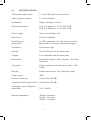
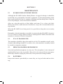
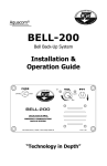
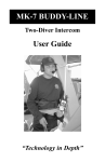
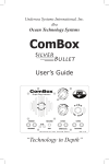
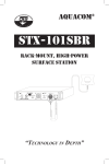
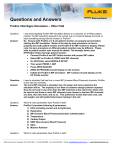
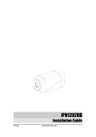
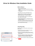
Undersea Systems International, Inc.
dba
Ocean Technology Systems
SP-100D2
2 Channel
Surface Buddy Phone ®
“Why Wait to Communicate?”
- NOTICE This manual and the information contained herein are provided for use as a maintenance and operation guide. No license or rights to manufacture, produce, and/
or sell either the manual or articles described herein are given. Undersea Systems
International, Inc., dba Ocean Technology Systems hereinafter referred to as OTS,
reserves the right to change specifications without notice. It is recommended that
all users read and fully understand this manual before using the SP-100D2.
All statements, technical information, and recommendations herein are based on
tests we believe to be reliable, but the accuracy or completeness thereof is not guaranteed; and the following is made in lieu of all warranties, expressed or implied,
including the implied warranties of merchantability and fitness for purpose: Seller’s
and Manufacturer’s only obligation shall be to replace such quantity of the product
proved to be defective. Before using, the user shall determine the suitability of the
product for intended use, and the user assumes all risk and liability whatsoever in
connection therewith. Neither Seller nor Manufacturer shall be liable either in tort
or in contract for any loss or damage—direct, incidental, or consequential—arising
from the use of or the inability to use the product. No statement or recommendation not contained herein shall have any force or effect unless it is in an agreement
signed by officers of the Seller and Manufacturer.
- IMPORTANT SAFETY NOTICE (Please read before using product.)
It is ABSOLUTELY ESSENTIAL that all operators are properly trained
and equipped and fully understand this user’s manual BEFORE attempting
to use the SP-100D2 Surface Buddy Phone®.
While the SP-100D2 provides good underwater communications, it does not
change or eliminate the potential hazards of diving!
Refer to the Library page of our Web site, www.oceantechnologysytems.com,
for a list of any changes made to this manual since its publication.
Copyright © 2008 by Undersea Systems International, Inc., dba
Ocean Technology Systems. All rights reserved.
Specifications subject to change without prior notice.
i
506131-000 (A)
Table of Contents
Section 1: Introduction ................................................................................1
1.1
General..........................................................................................1
1.2
Specifications................................................................................2
Section 2: Functions . ...................................................................................3
Section 3: Batteries ......................................................................................5
3.1
Battery Selection...........................................................................5
3.2
Battery Installation........................................................................5
3.3
Low-Battery Alert.........................................................................5
Section 4: Operation ....................................................................................7
4.1
Setup.............................................................................................7
4.2
Adjustments and Controls.............................................................8
4.2.1
Listening Volume............................................................8
4.2.2
Speaker On/Off...............................................................8
4.2.3
Channel Selection...........................................................8
4.3
Squelch..........................................................................................8
4.4
Reception......................................................................................8
4.5
Transmission.................................................................................9
4.6
Recording Communications.......................................................... 9
4.7
Helpful Hints................................................................................9
Section 5: Maintenance ............................................................................. 11
5.1
SP-100D2 Surface Buddy Phone® ............................................. 11
5.2
TCA-35 Transducer.................................................................... 11
5.3
HHM-3 Hand-Held Microphone................................................. 11
5.4
Batteries...................................................................................... 11
Limited Warranty ......................................................................................12
ii
Section 1
Introduction
Congratulations! You have just purchased one of the finest, state-of-the-art underwater communication systems available. The SP-100D2 Surface Buddy Phone® is a
compact, ultrasonic, single-sideband transceiver designed to allow surface-to-diver
and diver-to-surface through-water communications.
The SP-100D2 is the latest design of the SP-100 Buddy Phone, featuring innovative software-defined radio (SDR) technology that uses digital signal processing
(DSP) algorithms. This new design represents the latest in state-of-the-art communications technology, with a streamlined hardware design; greater precision in
frequency definition and in squelch sensitivity and selectivity; increased energy
efficiency, resulting in higher transmit power; enhanced reception sensitivity; and
clearer, higher quality sound.
The SP-100D2 offers many useful features to ensure user-friendly performance: a
front-panel squelch control; a panel speaker; a heavy-duty, water-resistant housing;
accommodation for a 12-volt external power supply; a hand-held microphone; and
much more. In all, the SP-100D2 Surface Buddy Phone® portable surface station
is designed with full functionality yet simplicity in mind.
1.1
GENERAL
This manual contains information regarding the SP-100D2 Surface Buddy Phone®
portable surface communication system. Section 1 contains general information
about the SP-100D2 and a table of specifications.
The following are provided with the SP-100D2:
• TCA-35 transducer cable assembly (p.n. 912077-000)
• HHM-3 hand-held microphone (p.n. 110025-000)
• EPP-2 external power cable (p.n. 912033-000)
• SP-100D2 user’s manual (document no. 506131-000)
• Warranty card (doc. no. 506014-000)
Optional accessories (sold separately):
• THB-14 headset with boom microphone (p.n. 900298-015)
1
1.2
SPECIFICATIONS
Transmitter output power:
1/2 watt PEP (peak envelope power)
Audio output to speaker:
1/2 watt (nominal)
Modulation:
Single sideband, no carrier
Operating channels:
Freq. A (Channel 1): 32.768 kHz USB
Freq. B (Channel 4): 31.250 kHz LSB
Power supply:
Sixteen AA alkaline cells
Battery life:
20 hours (nominal)
External power:
(front panel)
12 VDC, minimum of 1 amp. Access via front
panel with use of a mini double banana plug.
Transducer:
Piezoelectric type
Squelch:
On/off selected from the front panel
Volume:
User adjustable from the front panel
Microphone:
Hand-held, push-to-talk, dynamic, 500 ohm
impedance
Activation:
Upon connection of transducer cable to SP100D2
Housing:
Underwater Kinetics 309, ABS, heavy duty
Control panel:
ABS
Receiver sensitivity:
Greater than 100 dBv
Automatic Gain Control (AGC): Greater than 100 dBv
Transmitter speech frequency
bandwidth:
Housing dimensions:
300–3,500 Hz
Width: 9.00 inches
Height: 7.85 inches
Depth: 3.40 inches
2
SECTION 2
FUNCTIONS
Figure 1 depicts the SP-100D2 panel. The numbered text below is the key to the
indicated items in Figure 1. Text in all capital letters refers to the label on the
panel.
1. VOLUME:
Use the volume control to adjust the front-panel speaker
listening volume. The volume is increased by clockwise
rotation and decreased by counterclockwise rotation.
2. Phillips pan-head
screw:
One of eight #8-32 Phillips pan-head front-panel screws.
These screws are removed to take off the front panel for
access to the battery holders or the electronic module.
3. 12 VOLTS
This connector is used for an external 12-volt DC power
source. Ensure the source has a minimum of 1 amp current. We recommend that you use the supplied double
mini banana plug (the EPP-2 external power cable).
4. SPEAKER switch: If a headset is to be used, the front-panel speaker can be
turned off via this switch.
5. MICROPHONE: This receptacle is used for the HHM-3 hand-held, pushto-talk microphone (supplied with the SP-100D2).
6. XDUCER:
This female bulkhead Amp connector is used for connection of the 35-foot transducer cable. Ensure that the
o-ring is in place before connection. When the connection
is made to the TCA-35 transducer, the unit will power up
and stay powered up until the transducer is disconnected.
(Note: After disconnection of the transducer, there is a
45-second delay before power is turned off.)
7. RECORD OUT:
A recorder can be connected here. The signal level is “lineout,” suitable for most video and audio recorders. This feature
is useful for situations where documentation is important.
8. CHANNEL:
The channel switch is designed to select Frequency A
(Channel 1, switch to the left) or Frequency B (Channel
4, switch to the right).
9.
The front-panel speaker for listening to communications.
SPEAKER:
3
Figure 1
4
SECTION 3
BATTERIES
3.1battery selection
We recommend the use of alkaline AA batteries only. You will need sixteen fresh
1.5-volt AA-size batteries.
3.2
BATTERY INSTALLATION
To install the AA alkaline batteries, proceed as follows:
1. Open the lid by lifting the two latches located on either side of the carrying
handle.
2. Remove the eight #8 Phillips pan-head screws located on the front panel (Fig.
1, #2). You will need a Phillips-head screwdriver that fits a #8 screw.
3. Gently remove the front panel by grasping the volume control knob (Fig. 1,
#1) and transducer receptacle (Fig. 1, #6) and lifting the panel carefully. Be
careful not to stress the wires connecting the front panel to the battery holders
(Fig. 2, #3). Set aside the entire front panel with electronics attached.
4. Remove the foam padding that covers the batteries (Fig. 2, #1). Locate the
four AA battery holders (Fig. 2, #2), remove them, and install fresh AA batteries (four in each holder). The battery holders are marked with instructions
to show the correct orientation of the batteries. Make sure all batteries are
installed properly.
5. After the batteries are properly installed, put the holders back into the foam
pad (Fig. 2, #1) face down. Ensure all wires are dressed such that they are not
pinched. Replace the foam padding to cover the batteries (Fig. 2, #1). Replace
the front panel, and reinstall the eight panel screws with moderate tightness
(make sure you do not overtighten them).
Note: If necessary, you can use only one battery pack. The unit will fully operate,
but the battery life will be reduced approximately by half.
3.3
LOW-BATTERY ALERT
The SP-100D2 is equipped with a unique low-battery alert. As the battery level
decreases, you will start to hear a short three (3) tone burst, then says “Low Battery.”
5
WARNING!
If you are going to ship the SP-100D2, remove the batteries first to prevent
damage to the holders in the event the unit is dropped. Furthermore, all
batteries should be removed if you intend to store the SP-100D2 for an extended time.
Key
(1) Battery cover foam
(2) Batteries in holders
(3) Battery wires
(4) Battery support foam
Figure 2
6
SECTION 4
OPERATION
The SP-100D2 is designed to be portable and easy to operate. It is an ultrasonic,
through-water communication system. It will enable you to talk to all other divers
and/or surface stations on the same frequency and within range. When you speak
using the SP-100D2, your voice is sent out in an omni-directional pattern via the
transducer to all other transceivers. The transducer is the antenna that both sends
out the signal and picks up incoming signals.
4.1
Setup
After you have installed the batteries (Section 3.2), you are ready to set up your
SP-100D2 surface station.
1. Place the SP-100D2 on a surface that is secure from boat action and where the
transducer cable will not trip anyone or be damaged.
2. Open the case cover, and ensure that the o-ring is in place in the transducer
cable receptacle (Fig. 1, #6) on the front panel. Connect the TCA-35 transducer cable to the receptacle. Connecting the transducer cable powers up the
SP-100D2. (When not using the SP-100D2, disconnect the transducer cable
to conserve battery power.)
3. Lower the TCA-35 transducer into the water. If using a boat, lower the transducer so it clears the hull. If the surface station is set up on a beach, suspend
the transducer from a float.
Under no circumstances should the transducer lie on the bottom. Laying the
transducer on the bottom would reduce transmission and reception signal
strength, resulting in weak or no communications.
In swiftly flowing water, you may have to keep the transducer from angling
toward the surface. Tie a rope to the cable at the transducer end, and secure the
other end of the rope to a stable structure on the vessel (or wherever the surface
station is located). Hang a weight (about 1/2 pound should be sufficient) from
the transducer end of the rope, but make sure that the weight hangs below the
transducer to prevent transducer damage.
4. Adjust the volume (Fig. 1, #1) to a comfortable listening level.
5. If desired, turn on the squelch (Fig. 1, #8) to suppress background noise.
6. Connect the HHM-3 hand-held microphone (supplied with the SP-100D2) or
the THB-14 headset (sold separately) to the microphone receptacle (Fig. 1,
#5).
7
4.2
Adjustments AND CONTROLS
4.2.1 LISTENING VOLUME: The volume control knob (Fig. 1, #1) allows
adjustment of the listening volume of audio signal coming through the front-panel
speaker. Turn the volume control clockwise to increase the volume and counterclockwise to decrease it. If you are using a headset (the THB-14, sold separately),
the volume control knob also controls the listening volume through the headset.
4.2.2 SPEAKER ON/OFF: If you are using the optional THB-14 headset (part
no. 900298-015), you may want to turn off the front-panel speaker. This is done
with the speaker on/off switch (Fig. 1, #4).
4.2.3 CHANNEL SELECTION: The channel switch (Fig 1, #8) allows the user
to choose either Frequency A (Channel 1) or Frequency B (Channel 4). Having the
ability to select between channels is a feature useful for dive teams who have more
than one group. Note: Ensure all units are on the same channel before diving.
4.3
SQUELCH
The squelch helps suppress background noises created by sea creatures, human
activity, or other sources (e.g., snapping shrimp, croakers, motor boats, pool pumps).
Its innovative technology is unlike squelch systems used in the past: Instead of
relying simply on signal strength, it actually distinguishes between noise and voice.
The voice recognition capabilities of the SP-100D2 allow it to activate the panel
speaker with even the slightest voice in the greatest noise, such as that found on
an active reef. Therefore, the SP-100D2 squelch does not suffer the loss of range
encountered with other squelch systems, especially in high-noise environments.
The SP-100D2 squelch is fully automatic, so no adjustments are necessary.
4.4
Reception
When the SP-100D2’s power is activated by connecting the TCA-35 transducer
(Step 2 in Section 4.1), the unit enters the receive mode and listens for incoming
signals. Adjust the listening volume to a comfortable level (Section 4.2.1). If you
want to suppress background noises, turn on the squelch (see Section 4.3).
If you would prefer to use a headset, we offer an optional headset with boom microphone (model THB-14) that connects to the microphone jack on the SP-100D2
panel. You have the option of turning off the speaker (Section 4.2.2) while you use
the headset. The volume control knob (Fig. 1, #1) serves to adjust the headset’s
listening volume. When connecting the headset, be sure the listening volume is
turned down, because the volume is much louder in the headset than through the
speaker.
8
4.5
Transmission
To talk to a diver and/or another surface station, hold the HHM-3 microphone
within 1/4 inch of your lips (or ensure the boom microphone of the THB-14 headset is within 1/2 inch of your lips). Depress the push-to-talk (PTT) button on the
side of the microphone or headset, and speak slowly. When you release the PTT
button, the SP-100D2 will return to the receive mode. While the SP-100D2 is in
transmission mode, you will not hear any received communications.
4.6
Recording Communications
If you would like to record the communications, connect the recording device to the
“record out” jack (Fig. 1, #7). The jack accepts a male RCA phono plug. Ensure
the recorder is recording when the SP-100D2 is operated. All sounds outputted to
the speaker will be recorded at “line level.”
4.7
Helpful Hints
• Remember that all divers are hearing noise underwater (e.g., bubbles and biological noises). Everyone communicating should speak at a moderate voice level
and a bit more slowly than normal.
• Divers should try to be in an inhalation cycle when listening to a voice message;
doing so will help eliminate bubble noise while listening to messages.
• When talking to divers, keep in mind they have many things happening while
underwater. It is best to get the diver’s attention before giving him a message.
Example: “Mark, Mark, this is topside, come in Mark.” Mark would answer
back and then prepare for your message. Example: “Topside, this is Mark, go
ahead.”
• When transmitting, speak slowly and in one continuous sentence. Try not to
make long sentences. It is always a good idea to have the divers repeat the message back so you know they clearly understood your message. Remember that
listening to divers is usually easier than divers’ listening to the topside tender.
• It is important that the transducer be protected. It is designed using a material
that can break if sharply hit or impacted.
• Do not hang the transducer in a position that is blocked, and do not lay it on the
sea bottom.
• Inform the divers that if they go below a thermocline, they should inform everyone. If possible, lower the transducer to the same depth as the divers in the
thermocline.
• If you are using the SP-100D2 on a vessel, always remember to pull up the
9
transducer when moving the vessel. Many transducers have been lost when cut
off by a propeller.
• Keep the hand-held microphone as dry as possible. It is not waterproof.
• Place the SP-100D2 where it can be heard easily. If working on a boat, locate
a place where you can secure the unit where boat action will not cause it to fall.
Also remember to dress the transducer cable in such a way that divers and/or
topside personnel will not trip over it.
• If this is the first time you or any other member of your team is using communications, we recommend that your team get together to talk about the system.
Plan alternative communications in the event something is not working. A pool
session or practice in another controlled environment is the best preparation.
• Talking and listening while diving is something that takes practice and will
improve every time a team works together. The U.S. Navy has found that proficiency at through-water communications requires about three dives. Do not be
discouraged when you first start using underwater communications.
10
Section 5
Maintenance
5.1
SP-100D2 Surface BUDDY PHONE®
Although the SP-100D2 Surface Buddy Phone® is rugged in design, it should be
treated like any good-quality electronic equipment. Avoid transportation modes
that would expose the unit to constant vibrations and knocking about. Ship the
unit well packaged, without the batteries installed.
After use, wipe the unit free of dirt, debris, and water. Use a clean, soft cloth.
Warm water with a small amount of nonabrasive soap is the recommended cleaning solution.
When the SP-100D2 is not being used, it is a good idea to keep the cover securely
fastened.
Remember, when the transducer assembly is connected to the SP-100D2, the power
is on. To conserve energy when securing or cleaning the SP-100D2, disconnect the
transducer connector from the front panel.
5.2tCA-35 Transducer
The transducer should be kept clean and free of oils. The transducer itself can be
cleaned with rubbing alcohol. If wet after a dive, the transducer assembly should
be stored in a separate container.
5.3
HHM-3 HAND-HELD MICROPHONE
Store the hand-held microphone in a dry area. The microphone is not waterproof
and should be kept as dry as possible. Keep it free of water and from water spray.
Mild soap solution, wiping dry afterward, is the preferred cleaning method.
5.4
BATTERIES
Inspect the batteries periodically to ensure they are in good order and not leaking.
11
Undersea Systems International, Inc.
dba
Ocean Technology Systems
LIMITED WARRANTY
Ocean Technology Systems’ SP-100D2 Surface Buddy Phone® is fully
warranted against defects in materials and workmanship for a period of one
year from the time of purchase. Our obligation under this warranty is limited
to the replacement of any part or parts that prove to our satisfaction to have
been defective and that have not been misused or carelessly handled. Labor
is warranted for one year from time of purchase. The complete unit and/
or part must be returned to our factory, transportation charges prepaid. We
reserve the right to decline responsibility where repairs have been made or
attempted by other than an Ocean Technology Systems factory-trained service
center or properly trained personnel. In no event shall Ocean Technology
Systems be liable for consequential damages.
You can now register your product online at the OTS Web site. Just visit
http://www.oceantechnologysystems.com/register1.html.
Undersea Systems International, Inc.
dba
Ocean Technology Systems
3133 West Harvard Street, Santa Ana, CA 92704, USA
Telephone 714-754-7848 • Toll-free 800-550-1984 • Fax 714-966-1639
E-mail [email protected] • Web www.oceantechnologysystems.com
Copyright © 2008 by Undersea Systems International, Inc., dba
Ocean Technology Systems. All rights reserved.
Specifications subject to change without prior notice.
12
NOTES: