1
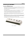
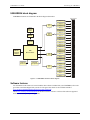
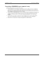
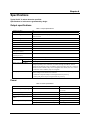
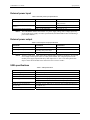
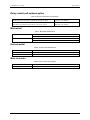
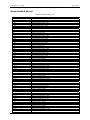
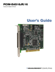
USB-ERB24 USB-based 24-Relay Module User's Guide Document Revision 6, August, 2006 © Copyright 2006, Measurement Computing Corporation Your new Measurement Computing product comes with a fantastic extra — Management committed to your satisfaction! Refer to www.mccdaq.com/execteam.html for the names, titles, and contact information of each key executive at Measurement Computing. Thank you for choosing a Measurement Computing product—and congratulations! You own the finest, and you can now enjoy the protection of the most comprehensive warranties and unmatched phone tech support. It’s the embodiment of our two missions: To offer the highest-quality, computer-based data acquisition, control, and GPIB hardware and software available—at the best possible price. To offer our customers superior post-sale support—FREE. Whether providing unrivaled telephone technical and sales support on our latest product offerings, or continuing that same first-rate support on older products and operating systems, we’re committed to you! Lifetime warranty: Every hardware product manufactured by Measurement Computing Corporation is warranted against defects in materials or workmanship for the life of the product. Products found defective are repaired or replaced promptly. Lifetime Harsh Environment Warranty®: We will replace any product manufactured by Measurement Computing Corporation that is damaged (even due to misuse) for only 50% of the current list price. I/O boards face some tough operating conditionssome more severe than the boards are designed to withstand. When a board becomes damaged, just return the unit with an order for its replacement at only 50% of the current list price. We don’t need to profit from your misfortune. By the way, we honor this warranty for any manufacturer’s board that we have a replacement for. 30 Day Money Back Guarantee: You may return any Measurement Computing Corporation product within 30 days of purchase for a full refund of the price paid for the product being returned. If you are not satisfied, or chose the wrong product by mistake, you do not have to keep it. Please call for an RMA number first. No credits or returns accepted without a copy of the original invoice. Some software products are subject to a repackaging fee. These warranties are in lieu of all other warranties, expressed or implied, including any implied warranty of merchantability or fitness for a particular application. The remedies provided herein are the buyer’s sole and exclusive remedies. Neither Measurement Computing Corporation, nor its employees shall be liable for any direct or indirect, special, incidental or consequential damage arising from the use of its products, even if Measurement Computing Corporation has been notified in advance of the possibility of such damages. HM USB-ERB24.doc ii Trademark and Copyright Information TracerDAQ, Universal Library, Harsh Environment Warranty, Measurement Computing Corporation, and the Measurement Computing logo are either trademarks or registered trademarks of Measurement Computing Corporation. Windows, Microsoft, and Visual Studio are either trademarks or registered trademarks of Microsoft Corporation LabVIEW is a trademark of National Instruments. CompactFlash is a registered trademark of SanDisk Corporation. All other trademarks are the property of their respective owners. Information furnished by Measurement Computing Corporation is believed to be accurate and reliable. However, no responsibility is assumed by Measurement Computing Corporation neither for its use; nor for any infringements of patents or other rights of third parties, which may result from its use. No license is granted by implication or otherwise under any patent or copyrights of Measurement Computing Corporation. All rights reserved. No part of this publication may be reproduced, stored in a retrieval system, or transmitted, in any form by any means, electronic, mechanical, by photocopying, recording, or otherwise without the prior written permission of Measurement Computing Corporation. Notice Measurement Computing Corporation does not authorize any Measurement Computing Corporation product for use in life support systems and/or devices without prior written consent from Measurement Computing Corporation. Life support devices/systems are devices or systems which, a) are intended for surgical implantation into the body, or b) support or sustain life and whose failure to perform can be reasonably expected to result in injury. Measurement Computing Corporation products are not designed with the components required, and are not subject to the testing required to ensure a level of reliability suitable for the treatment and diagnosis of people. iii Table of Contents Preface About this User’s Guide ......................................................................................................................vi What you will learn from this user’s guide........................................................................................................vi Conventions in this user’s guide........................................................................................................................vi Where to find more information ........................................................................................................................vi Chapter 1 Introducing the USB-ERB24............................................................................................................. 1-1 Overview: USB-ERB24 features.................................................................................................................... 1-1 USB-ERB24 block diagram ........................................................................................................................... 1-2 Software features ............................................................................................................................................ 1-2 Connecting a USB-ERB24 to your computer is easy ..................................................................................... 1-3 Chapter 2 Installing the USB-ERB24................................................................................................................. 2-1 What comes with your USB-ERB24 shipment? ............................................................................................. 2-1 Hardware ....................................................................................................................................................................... 2-1 Additional documentation.............................................................................................................................................. 2-1 Unpacking the USB-ERB24 ........................................................................................................................... 2-2 Installing the software .................................................................................................................................... 2-2 Installing the USB-ERB24 ............................................................................................................................. 2-2 Configuring the hardware switches................................................................................................................................ 2-2 Connecting the external power supply ........................................................................................................................... 2-3 Connecting the USB-ERB24 to your system ................................................................................................................. 2-4 Chapter 3 Functional Details ............................................................................................................................. 3-1 Internal components ....................................................................................................................................... 3-1 USB in connector........................................................................................................................................................... 3-1 USB out connector......................................................................................................................................................... 3-1 External power connectors............................................................................................................................................. 3-1 USB LED....................................................................................................................................................................... 3-2 PWR LED...................................................................................................................................................................... 3-2 Invert/non-invert switch (S1) ......................................................................................................................................... 3-2 Pull-up/pull-down switch (S2) ....................................................................................................................................... 3-3 Screw terminals.............................................................................................................................................................. 3-3 Daisy chaining additional relays to the USB-ERB24 ..................................................................................... 3-3 Power limitations using multiple USB-ERB24 devices ................................................................................. 3-4 Voltage drop .................................................................................................................................................................. 3-4 Relay configuration ........................................................................................................................................ 3-4 Relay contact protection circuit for inductive loads....................................................................................................... 3-5 Chapter 4 Specifications.................................................................................................................................... 4-1 Output specifications ...................................................................................................................................... 4-1 Power.............................................................................................................................................................. 4-1 External power input ...................................................................................................................................... 4-2 External power output .................................................................................................................................... 4-2 USB specifications ......................................................................................................................................... 4-2 Relay contact pull-up/down option................................................................................................................. 4-3 Mechanical ..................................................................................................................................................... 4-3 Environmental ................................................................................................................................................ 4-3 iv USB-ERB24 User's Guide Main connector ............................................................................................................................................... 4-3 Screw terminal pin out.................................................................................................................................... 4-4 v Preface About this User’s Guide What you will learn from this user’s guide This user’s guide explains how to install, configure, and use the USB-ERB24 so that you get the most out of its electromechanical relay features. This user's guide also refers you to related documents available on our web site, and to technical support resources. Conventions in this user’s guide For more information on … Text presented in a box signifies additional information and helpful hints related to the subject matter you are reading. Caution! Shaded caution statements present information to help you avoid injuring yourself and others, damaging your hardware, or losing your data. <#:#> Angle brackets that enclose numbers separated by a colon signify a range of numbers, such as those assigned to registers, bit settings, etc. bold text Bold text is used for the names of objects on the screen, such as buttons, text boxes, and check boxes. For example: 1. Insert the disk or CD and click the OK button. italic text Italic text is used for the names of manuals and help topic titles, and to emphasize a word or phrase. For example: The InstaCal installation procedure is explained in the Quick Start Guide. Never touch the exposed pins or circuit connections on the board. Where to find more information The following electronic documents provide helpful information relevant to the operation of the USB-ERB24. MCC's Specifications: USB-ERB24 (the PDF version of the Specifications chapter in this guide) is available on our web site at www.mccdaq.com/pdfs/USB-ERB24.pdf. MCC's Quick Start Guide is available on our web site at www.mccdaq.com/PDFmanuals/DAQ-Software-Quick-Start.pdf. MCC's Guide to Signal Connections is available on our web site at www.mccdaq.com/signals/signals.pdf. MCC's Universal Library User's Guide is available on our web site at www.mccdaq.com/PDFmanuals/sm-ul-user-guide.pdf. MCC's Universal Library Function Reference is available on our web site at www.mccdaq.com/PDFmanuals/sm-ul-functions.pdf. MCC's Universal Library for LabVIEW™ User’s Guide is available on our web site at www.mccdaq.com/PDFmanuals/SM-UL-LabVIEW.pdf. USB-ERB24 User's Guide (this document) is also available on our web site at www.mccdaq.com/PDFmanuals/USB-ERB24.pdf. vi Chapter 1 Introducing the USB-ERB24 Overview: USB-ERB24 features This user's guide contains all of the information you need to connect the USB-ERB24 to your computer and to the external devices you want to control. You can use the USB-ERB24 in your control applications to switch on and off a variety of devices, such as fans, blowers, pumps, etc. The USB-ERB24 is a USB 2.0 full-speed electromechanical relay module supported under popular Microsoft® Windows® operating systems. The USB-ERB24 has 24 single-pole double-throw (SPDT) Form C electromechanical relays. The digital I/O lines on your MCC USB Series board directly control the relays on your USB-ERB24. You connect your field wiring directly to the board's screw terminals. The screw terminals provide three connections to each relay – normally open (NO), normally closed (NC), and common (C). You can configure the logic polarity and power-on state of each bank of relays with on-board switches. The relays are configurable as two banks of eight and two banks of four. Switch settings can be read back with software. The USB-ERB24 is powered by an external 9 V, 3 A regulated power supply that is shipped with the device. A USB cable is also included. Power OUT and USB OUT connectors let you power and control multiple MCC USB Series boards from one external power source and one USB port in a daisy chain fashion. Depending on your load requirement, daisy chained boards may require a separate power supply. The USB-ERB24 is enclosed in a rugged housing that you can mount on a DIN rail or on a bench (Figure 1-1). Figure 1-1. USB-ERB24 1-1 USB-ERB24 User's Guide Introducing the USB-ERB24 USB-ERB24 block diagram USB-ERB24 functions are illustrated in the block diagram shown here. Relay 13 Relay 12 500 mA USB 2.0 compliant interface USB Microcontroller Relay 11 Relay driver 8 Relay 10 Relay 9 Relay 8 Relay 7 Switch S1 (inv/non-inv) Switch S2 (pull-up/down) Relay 6 Relay driver 8 Relay 5 Relay 4 Relay 3 Relay 2 Relay 1 24 23 22 21 20 19 18 17 16 15 14 Relay 14 13 Relay 15 12 Relay 16 Power Regulator 11 Relay 17 10 Relay 18 9 Relay 19 8 4 7 Relay driver Power Monitor 6 Relay 20 5 Relay 21 4 9.0 V External Power Relay 22 3 4 2 Relay 23 Relay driver 1 Relay 24 NC C NO NC C NO NC C NO NC C NO NC C NO NC C NO NC C NO NC C NO NC C NO NC C NO NC C NO NC C NO NC C NO NC C NO NC C NO NC C NO NC C NO NC C NO NC C NO NC C NO NC C NO NC C NO NC C NO NC C NO Screw terminal Figure 1-2. USB-ERB24 functional block diagram Software features For information on the features of InstaCal and the other software included with your USB-ERB24, refer to the Quick Start Guide that shipped with your device. The Quick Start Guide is also available in PDF at www.mccdaq.com/PDFmanuals/DAQ-Software-Quick-Start.pdf. Check www.mccdaq.com/download.htm for the latest software version or versions of the software supported under less commonly used operating systems. 1-2 USB-ERB24 User's Guide Introducing the USB-ERB24 Connecting a USB-ERB24 to your computer is easy Installing a data acquisition device has never been easier. The USB-ERB24 relies upon the Microsoft Human Interface Device (HID) class drivers. The HID class drivers ship with every copy of Windows that is designed to work with USB ports. We use the Microsoft HID because it is a standard, and its performance delivers full control and maximizes data transfer rates for your USB-ERB24. No third-party device driver is required. You can connect the USB-ERB24 before or after you install the software, and without powering down your computer first. When you connect an HID to your system, your computer automatically detects it and configures the necessary software. You can connect multiple HID peripherals to your system using a USB hub. You can connect your system to various devices using a standard four-wire cable. The USB connector replaces the serial and parallel port connectors with one standardized plug and port combination. Data can flow two ways between a computer and peripheral over USB connections. 1-3 Chapter 2 Installing the USB-ERB24 What comes with your USB-ERB24 shipment? The following items are shipped with the USB-ERB24. Hardware USB-ERB24 External power supply and cord (CB-PWR-9V3A) – 9 volt, 3 amp DC power supply USB cable (2 meter length) Additional documentation In addition to this hardware user's guide, you should also receive the Quick Start Guide (available in PDF at www.mccdaq.com/PDFmanuals/DAQ-Software-Quick-Start.pdf). This booklet supplies a brief description of the software you received with your USB-ERB24 and information regarding installation of that software. Please read this booklet completely before installing any software or hardware. 2-1 USB-ERB24 User's Guide Installing the USB-ERB24 Unpacking the USB-ERB24 As with any electronic device, you should take care while handling to avoid damage from static electricity. Before removing the USB-ERB24 from its packaging, ground yourself using a wrist strap or by simply touching the computer chassis or other grounded object to eliminate any stored static charge. If your USB-ERB24 is damaged, notify Measurement Computing Corporation immediately by phone, fax, or email. For international customers, contact your local distributor where you purchased the USB-ERB24. Phone: 508-946-5100 and follow the instructions for reaching Tech Support. Fax: 508-946-9500 to the attention of Tech Support Email: [email protected] Installing the software Refer to the Quick Start Guide for instructions on installing the software on the Measurement Computing Data Acquisition Software CD. This booklet is available in PDF at www.mccdaq.com/PDFmanuals/DAQ-SoftwareQuick-Start.pdf. Installing the USB-ERB24 The USB-ERB24 has two on-board switches that you set to configure the relay logic polarity and the resistor pull-up/down configuration. Configure these switches before you connect the external power supply to the USB-ERB24. Factory-configured default settings are listed in Table 2-1. Refer to Figure 3-1 for the location of each switch on the USB-ERB24. Configuring the hardware switches The USB-ERB24 has two on-board switches that you set to configure the relay control logic polarity and the relay power-on state. Factory-configured default settings are listed in Table 2-1. Refer to Figure 3-1 for the location of each switch on the USB-ERB24. Table 2-1. Default switch configuration Board label Description Default setting INVERT NON-INVERT S1 Pull DOWN PULL UP S2 Configures the relay control logic parity per relay bank for invert or non-invert logic. Non-invert Configures the relay power-on state per relay bank for pull-up or pull-down. Pull-down Each DIP switch sets the configuration of one relay group. The DIP switch labeled A configures relays 1 to 8, the switch labeled B configures relays 9 to 16, the switch labeled CL configures relays 17 to 20, and the switch labeled CH configures relays 21 to 24 (Figure 2-3). Configures relays 9-16 Configures relays17-20 Configures relays21-24 A B CL CH Figure 2-3. Typical board switch Port A consists of relays 1 through 8, Port B consists of relays 9 through 16, Port CL consists of relays 17 through 20, and Port CH consists of relays 21 through 24. Remove from the enclosure to access the on-board switches To change the configuration of a switch, you must first remove the USB-ERB24 from the enclosure. 2-2 USB-ERB24 User's Guide Installing the USB-ERB24 Relay control logic polarity Configure the Invert/non-invert switch (S1) to set the relay control logic polarity for each relay bank for invert or non-invert. By default, this switch is shipped with all banks configured for non-inverted logic, as shown in Figure 2-4. INVERT NON-INVERT A B CL CH S1 Figure 2-4. Relay logic switch S1 NON-INVERT mode: when "0" is written or read back via the USB bus, the relays are not energized. INVERT mode: when "0" is written or read back via the USB bus, the relays are energized. Switch settings for polarity can be read back via software through the USB bus. Switch settings for S1 do not affect the power-on condition. Relay power-on state Configure the Pull-up/pull-down switch (S2) to set the state of each relay bank at power-up. By default, this product is shipped with the switch for all banks configured for pull-down (relays inactive at power up), as shown in Figure 2-5. Switch settings can be read back via software through the USB bus. PULL DOWN PULL UP A B CL CH S2 Figure 2-5. Resistor pull-up/down switch S2 PULL-UP: the relays are put into an energized state at power-up, regardless of the state of switch S1 PULL-DOWN: the relays are put into a non-energized state at power-up. Connecting the external power supply Power to the USB-ERB24 is provided with the 9 V, 3 A external power supply (CB-PWR-9V3A). You must connect the external power supply before connecting the USB connector to the USB-ERB24. To connect the power supply to your USB-ERB24, do the following: 1. Connect the external power cord to the power connector labeled POWER IN on the USB-ERB24 enclosure (PWR IN on the board). Refer to Figure 3-1 for the location of this connector. 2. Plug the AC adapter into a power outlet. The PWR LED illuminates green when 9 V power is supplied to the USB-ERB24. If the voltage supply is less than 6.0 V or more than 12.5 V, the PWR LED does not light. Do not connect external power to the POWER OUT connector The power connector labeled POWER OUT on the enclosure (PWR OUT on the board) is used to provide power to an additional MCC USB Series product. If you connect the external power supply to the POWER OUT connector, the USB-ERB24 does not receive power, and the PWR LED will not illuminate. 2-3 USB-ERB24 User's Guide Installing the USB-ERB24 Connecting the USB-ERB24 to your system To connect the USB-ERB24 to your system, turn your computer on, and connect the USB cable to a USB port on your computer or to an external USB hub that is connected to your computer. The USB cable provides communication to the USB-ERB24. When you connect the USB-ERB24 for the first time, a Found New Hardware popup balloon (Windows XP) or dialog (other Windows versions) opens as the USB-ERB24 is detected. When this balloon or dialog closes, the installation is complete. The USB LED should flash and then remain lit. This indicates that communication is established between the USB-ERB24 and your computer. If you are running Windows XP and connect the USB-ERB24 to a USB 1.1 port, a balloon displays the message "Your USB device can perform faster if you connect to a USB 2.0 port." You can ignore this message. The USB-ERB24 will function properly when connected to a USB 1.1 port. Caution! Do not disconnect any device from the USB bus while the computer is communicating with the USB-ERB24, or you may lose data and/or your ability to communicate with the USB-ERB24. If the LED turns off If the LED is lit but then turns off, the computer has lost communication with the USB-ERB24. To restore communication, disconnect the USB cable from the computer, and then reconnect it. This should restore communication, and the LED should turn back on. 2-4 Chapter 3 Functional Details Internal components The USB-ERB24 has the following internal components, as shown in Figure 3-1. Two (2) USB connectors Two (2) external power connectors USB LED PWR LED Invert/non-invert switch (S1) — sets the relay control logic polarity Pull-up/down switch (S2) — sets the relay power-on state Screw terminals USB IN POWER IN USB OUT POWER OUT Invert/non-invert switch (S1) Pull-up/pull-down switch (S2) PWR LED USB LED Screw terminals Figure 3-1. USB-ERB24 components USB in connector The USB out connector is labeled USB IN on the board and enclosure. The USB IN connector is a USB 2.0 full-speed input connector that you connect to the USB port on your computer (or USB hub connected to your computer). This connector supports USB 1.1, USB 2.0 devices. USB out connector The USB out connector is labeled USB OUT on the board and enclosure. The USB OUT connector is a downstream hub output port intended for use with other MCC USB Series products only. The USB hub is self-powered, and can provide 100 mA maximum current at 5 V. For information on daisy chaining to other MCC USB Series products, refer to Daisy chaining additional modules to the USB-ERB08 on page 3-3. External power connectors The USB-ERB24 has two external power connectors labeled POWER IN and POWER OUT on the enclosure. The POWER IN connector is labeled PWR IN and P19 on the board, and the POWER OUT connector is labeled PWR OUT and P20 on the board. Connect the POWER IN connector to the supplied +9 V external power supply. External power is required to operate the USB-ERB24. The POWER OUT connector lets you power additional daisy chained MCC USB Series products from a single external power supply. Depending on your load requirements, daisy chained products may require a separate power supply. Refer to "Power limitations using multiple USB-ERB24 devices" on page 3-4 for more information. 3-1 USB-ERB24 User's Guide Functional Details USB LED The USB LED indicates the communication status of the USB-ERB24. It uses up to 5 mA of current and cannot be disabled. Table 3-2 explains the USB LED function. Table 3-2. USB LED Illumination USB LED illumination Indication Steady green Pulsing green The USB-ERB24 is connected to a computer or external USB hub. Initial communication is established between the USB-ERB24 and the computer, or data is being transferred. PWR LED The USB-ERB24 incorporates an on-board voltage supervisory circuit that monitors the external 9 V power. If the input voltage falls outside of the specified range, the PWR LED shuts off. Table 3-3 explains the function of the PWR LED. Table 3-3. PWR LED Illumination PWR LED illumination Indication Steady green Off External power is supplied to the USB-ERB24. Power is not supplied by the external supply, or a power fault has occurred. A power fault occurs when the input power falls outside of the specified voltage range of the external supply (6.0 V to 12.5 V). Invert/non-invert switch (S1) The Invert/non-invert switch (S1) sets the relay control logic per relay bank to either inverted or non-inverted. By default, switch S1 is configured for non-invert (see Figure 3-2). INVERT NON-INVERT A B CL CH S1 Figure 3-2. Switch S1 default configuration The switch labeled A configures relays 1 through 8, the switch labeled B configures relays 9 through 16, the switch labeled CH configures relays 17 through 20, the switch labeled CL configures relays 21 through 24. NON-INVERT: when "0" is written or read back via the USB bus, the relays are not energized. INVERT: when "0" is written or read back via the USB bus, the relays are energized. Switch settings do not affect the power-on condition. Use InstaCal to read the current logic setting for each module group. 3-2 USB-ERB24 User's Guide Functional Details Pull-up/pull-down switch (S2) The Pull-up/pull-down switch (S2) sets the power-on state of each relay bank. By default, switch S2 is configured for pull-down (relays inactive at power-up – see Figure 3-3). PULL DOWN PULL UP A B CL CH S2 Figure 3-3. Switch S2 default configuration The switch labeled A configures relays 1 through 8, the switch labeled B configures relays 9 through 16, the switch labeled CH configures relays 17 through 20, the switch labeled CL configures relays 21 through 24. PULL UP: the relay energizes at power-up, regardless of the state of switch S1. PULL DOWN: the relays are not energized at power-up. Use InstaCal to read the current power-on state setting for each module group. Screw terminals Connect external devices to the relay contacts using the USB-ERB24 board's 24 sets of screw terminals. Each relay has a normally closed (NC), common (C), and normally open (NO) contact. Figure 3-4 shows the screw terminals on a typical relay channel. NC C NO Figure 3-4. Typical relay channel Each screw terminal is identified with a label on the board and on the underside of the enclosure lid. Caution! Before connecting wires to the screw terminals, turn off the power to the USB-ERB24, and make sure that the signal wires do not contain live voltages. Use 12-22 AWG wire for your signal connections. Properly insulate the wires to avoid any short circuit to the other channels, ground, or other points on the board. Caution! Keep the length of stripped wire at a minimum to avoid a short to the enclosure! When connecting your field wiring to the screw terminals, use the strip gage on the terminal strip, or strip to 5.5 - 7.0 mm (0.215" to 0.275") long. Daisy chaining additional relays to the USB-ERB24 Daisy chained MCC USB Series products connect to the USB bus through the high-speed hub on the USBERB24. You can daisy chain a maximum of four MCC USB Series products to a single USB 2.0 port or USB 1.1 port on your computer. MCC USB Series products are USB 1.1 full-speed devices that provide a signaling bit rate of 12 Mb/s. The throughput rate is shared by all devices connected to the USB bus. Use the supplied cable or an equivalent full-speed cables cable when daisy chaining to additional MCC USB Series products. To daisy chain two or more USB-ERB24 relay boards, follow the steps below. This procedure assumes you already have one USB-ERB24 connected to a computer and to an external power source. The USB-ERB24 already connected to the computer is referred to as the connected module. The USB-ERB24 you want to daisy chain to the connected board is referred to as the new module. 3-3 USB-ERB24 User's Guide 1. Functional Details Connect the POWER OUT connector on the connected module to the POWER IN connector on the new module. This step is required only if you plan to daisy chain power to another module. 2. Connect the USB OUT connector on the connected module to the USB IN connector on the new module. 3. To add another module, repeat steps 1-2, with the module you just connected now being the connected module. A daisy chain example is shown in Figure 3-5. Note that the last board in the chain is supplied with external power. USB port to USB IN POWER OUT to POWER IN USB OUT to USB IN USB OUT to USB IN CB-PWR-9V3A supply to POWER IN CB-PWR-9V3A supply to POWER IN Figure 3-5. Daisy chain connections Power limitations using multiple USB-ERB24 devices When daisy chaining additional MCC USB Series products to the USB-ERB24, you must ensure that you provide adequate power to each board that you connect. The USB-ERB24 is powered with a 9 VDC nominal, 3.0 A external power supply. Voltage drop A drop in voltage occurs with each board connected in a daisy chain system. The voltage drop between the power supply input and the daisy chain output is 0.5 V maximum. Factor in this voltage drop when you configure a daisy chain system to ensure that at least 6.0 VDC is provided to the last board in the chain. Relay configuration You can install a pull-up or pull-down resistor at the NO and NC terminals on each relay. Note that the pull-up resistors are tied to the 5 V power and should be considered when calculating the power budget. The relay configuration is illustrated in the following schematic User-installed pull-up / pull-down resistor +5 GND +5 GND Buffer/ driver Digital output from the user NO C NC Screw terminals (3 per relay) 10 k resistor Pull-up/pull-down switch S2 Figure 3-6. Relay configuration 3-4 USB-ERB24 User's Guide Functional Details The relay contacts associated that are with each relay location are listed in Table 3-4. Table 3-4. Relay locations and associated contacts R35, R36, R41, R43, R45, R47, R49, R51, R87, R89, R91, R93, R96, R98, R100, R102, R103, R105, R107, R109, R112, R114, R116, R118 R37, R40, R42,R44, R46, R48, R50, R52, R88, R90, R92, R94, R95, R97, R99, R101, R104, R106, R108, R110, R111, R113, R115, R117 Relays NO contact pull-up (to USB +5 V) / pull-down, user installed. Relays NC contact pull-up (to USB +5 V) / pull-down, user installed Relay contact protection circuit for inductive loads When you connect an inductive load to a relay, energy stored in the inductive load can induce a large voltage surge when you switch the relay. This voltage can severely damage the relay contacts. To limit the voltage surge across the inductive load in a DC circuit, install a kickback diode across the inductive load. Refer to the contact protection circuit in Figure 3-7. For AC loads, install a metal oxide varistor (MOV). Relay NO C NC + V - Inductive Load Kickback Diode Figure 3-7. Relay contact protection circuit 3-5 Chapter 4 Specifications Typical for 25 °C unless otherwise specified. Specifications in italic text are guaranteed by design. Output specifications Table 1. Output specifications Number of relays Relay configuration Contact configuration Contact rating Contact resistance Operate time Release time Vibration Shock Dielectric isolation (between relay open contact) Dielectric isolation (between PCB output lines) Life expectancy Power on state S2 = pull-up S2 = pull-down Relay control logic polarity Pull-up / pull-down 24 2 banks of 8 and 2 banks of 4 24 Form C (SPDT) Normally Open, Normally Closed and Common available at screw terminals 6 A @ 240 VAC or 28 VDC resistive 100 milliohms max (initial value) 10 milliseconds max 5 milliseconds max 10 to 55 Hz (amplitude 1.5 mm) 10 G (11 milliseconds) 300 VAC, 50/60 Hz (1 minute) 500VAC, 50/60 Hz (1 minute) 10 million mechanical operations, min Energized. NO in contact with Common Not energized. NC in contact to Common User-configurable per bank via switch S1 for invert or non-invert (default). Switch settings for polarity can be read back via software through the USB bus. Switch settings do not affect the power on condition. Non-invert mode, when "0" is written or read back via the USB bus, relays are not energized. Invert mode, when "0" is written or read back via the USB bus, relays are energized. User-configurable per bank via switch S2 for pull-down (default) or pull-up. Switch settings can be read back via software. Pull-down will put the relays in non-energized mode on power up. Pull-up will put the relays in energized mode on power up. Power Table 2. Power specifications Parameter Conditions Specification All modes of operation MCC p/n CB-PWR-9V3A Vext < 6.0 V, Vext > 12.5 V 6.0 V < Vext < 12.5 V All relays on, 100 mA downstream hub power All relays off, 100 mA downstream hub power 4.75 V min. to 5.25 V max. 10 mA max 9 V ±10% @ 3 A PWR LED = Off (power fault) PWR LED = On 1.5 A typ, 1.8 A max 230 mA typ, 270 mA max USB +5 V input voltage range USB +5 V supply current External power supply (required) Voltage supervisor limits - PWR LED External power consumption 4-1 USB-ERB24 User's Guide Specifications External power input Table 3. External power input specifications Parameter Conditions Specification 6.0 V > Vext or Vext > 12.5 V 6.0 V < Vext < 12.5 V MCC p/n CB-PWR-9V3A +6.0 VDC to 12.5 VDC (9 VDC power supply included). PWR LED = Off (power fault) PWR LED = On +9 V ±10%, @ 3 A External power input Voltage supervisor limits - PWR LED (Note 1) External power adapter (included) Note 1: The USB-ERB24 monitors the external +9 V power supply voltage with a voltage supervisory circuit. If this power supply exceeds its specified limit, the PWR LED will turn off indicating a power fault condition. External power output Table 4. External power output specifications Parameter Conditions External power output - current range External power output (Note 2) Compatible cable(s) for daisy chain Note 2: Specification Voltage drop between power input and daisy chain power output C-MAPWR-x 4.0 A max. 0.5 V max x = 2 , 3 or 6 feet The daisy chain power output option allows multiple MCC USB Series products to be powered from a single external power source in a daisy chain fashion. The voltage drop between the module power supply input and the daisy chain output is 0.5 V max. Users must plan for this drop to ensure the last module in the chain will receive at least 6.0 VDC. USB specifications Table 5. USB specifications USB "B" connector USB device type Device compatibility USB "A" connector USB hub type Compatible products USB cable type (upstream and downstream) Input USB 2.0 (full-speed) USB 1.1, USB 2.0 Downstream hub output port Supports USB 2.0 high-speed, full-speed and low-speed operating points Self-powered, 100 mA max downstream VBUS capability MCC USB Series devices A-B cable, UL type AWM 2527 or equivalent. (min 24 AWG VBUS/GND, min 28 AWG D+/D-) USB cable length 3 meters max. 4-2 USB-ERB24 User's Guide Specifications Relay contact pull-up/down option Table 6. Relay pull-up/pull-down specifications R35, R36, R41, R43, R45, R47, R49, R51, R87, R89, R91, R93, R96, R98, R100, R102, R103, R105, R107, R109, R112, R114, R116, R118 R37, R40, R42,R44, R46, R48, R50, R52, R88, R90, R92, R94, R95, R97, R99, R101, R104, R106, R108, R110, R111, R113, R115, R117 Relays NO contact pull-up (to USB +5 V) / pull-down, user installed. Relays NC contact pull-up (to USB +5 V) / pull-down, user installed Mechanical Table 7. Mechanical specifications Card dimensions Enclosure dimensions 431.8 mm (L) x 121 mm (W) x 20.3 mm (H) 17.0" (L) x 4.8" (W) x 0.8" (H) 482.6 mm (L) x 125.7 mm (W) x 58.9 mm (H) 19.00" (L) x 4.95" (W)x 2.32" (H) Environmental Table 8. Environmental specifications Operating temperature range Storage temperature range Humidity 0 to 70 °C -40 to 100 °C 0 to 95% non-condensing Main connector Table 9. Main connector specifications Connector type Wire gauge range Screw terminal 12 to 22 AWG 4-3 USB-ERB24 User's Guide Specifications Screw terminal pin out Table 10. Screw terminal pin out Pin 1-NC 1-C 1-NO 2-NC 2-C 2-NO 3-NC 3-C 3-NO 4-NC 4-C 4-NO 5-NC 5-C 5-NO 6-NC 6-C 6-NO 7-NC 7-C 7-NO 8-NC 8-C 8-NO 9-NC 9-C 9-NO 10-NC 10-C 10-NO 11-NC 11-C 11-NO 12-NC 12-C 12-NO 13-NC 13-C 13-NO 14-NC 14-C 14-NO 15-NC 15-C 15-NO 16-NC 16-C 16-NO 17-NC 17-C 17-NO 18-NC 18-C 18-NO 19-NC 19-C 19-NO 20-NC 20-C 20-NO 21-NC 21-C 21-NO 22-NC 22-C Signal Name Relay 1 Normally Closed contact Relay 1 Common contact Relay 1 Normally Open contact Relay 2 Normally Closed contact Relay 2 Common contact Relay 2 Normally Open contact Relay 3 Normally Closed contact Relay 3 Common contact Relay 3 Normally Open contact Relay 4 Normally Closed contact Relay 4 Common contact Relay 4 Normally Open contact Relay 5 Normally Closed contact Relay 5 Common contact Relay 5 Normally Open contact Relay 6 Normally Closed contact Relay 6 Common contact Relay 6 Normally Open contact Relay 7 Normally Closed contact Relay 7 Common contact Relay 7 Normally Open contact Relay 8 Normally Closed contact Relay 8 Common contact Relay 8 Normally Open contact Relay 9 Normally Closed contact Relay 9 Common contact Relay 9 Normally Open contact Relay 10 Normally Closed contact Relay 10 Common contact Relay 10 Normally Open contact Relay 11 Normally Closed contact Relay 11 Common contact Relay 11 Normally Open contact Relay 12 Normally Closed contact Relay 12 Common contact Relay 12 Normally Open contact Relay 13 Normally Closed contact Relay 13 Common contact Relay 13 Normally Open contact Relay 14 Normally Closed contact Relay 14 Common contact Relay 14 Normally Open contact Relay 15 Normally Closed contact Relay 15 Common contact Relay 15 Normally Open contact Relay 16 Normally Closed contact Relay 16 Common contact Relay 16 Normally Open contact Relay 17 Normally Closed contact Relay 17 Common contact Relay 17 Normally Open contact Relay 18 Normally Closed contact Relay 18 Common contact Relay 18 Normally Open contact Relay 19 Normally Closed contact Relay 19 Common contact Relay 19 Normally Open contact Relay 20 Normally Closed contact Relay 20 Common contact Relay 20 Normally Open contact Relay 21 Normally Closed contact Relay 21 Common contact Relay 21 Normally Open contact Relay 22 Normally Closed contact Relay 22 Common contact 4-4 USB-ERB24 User's Guide Pin 22-NO 23-NC 23-C 23-NO 24-NC 24-C 24-NO Specifications Signal Name Relay 22 Normally Open contact Relay 23 Normally Closed contact Relay 23 Common contact Relay 23 Normally Open contact Relay 24 Normally Closed contact Relay 24 Common contact Relay 24 Normally Open contact 4-5 Declaration of Conformity Manufacturer: Address: Category: Measurement Computing Corporation 10 Commerce Way Suite 1008 Norton, MA 02766 USA Electrical equipment for measurement, control and laboratory use. Measurement Computing Corporation declares under sole responsibility that the product USB-ERB24 to which this declaration relates is in conformity with the relevant provisions of the following standards or other documents: EU EMC Directive 89/336/EEC: Electromagnetic Compatibility, EN 61326 (1997) Amendment 1 (1998) Emissions: Group 1, Class A EN 55011 (1990)/CISPR 11: Radiated and Conducted emissions. Immunity: EN61326, Annex A IEC 1000-4-2 (1995): Electrostatic Discharge immunity, Criteria C. IEC 1000-4-3 (1995): Radiated Electromagnetic Field immunity Criteria C. IEC 1000-4-4 (1995): Electric Fast Transient Burst immunity Criteria A. IEC 1000-4-5 (1995): Surge immunity Criteria C. IEC 1000-4-6 (1996): Radio Frequency Common Mode immunity Criteria A. IEC 1000-4-8 (1994): Magnetic Field immunity Criteria A. IEC 1000-4-11 (1994): Voltage Dip and Interrupt immunity Criteria A. Declaration of Conformity based on tests conducted by Chomerics Test Services, Woburn, MA 01801, USA in June, 2005. Test records are outlined in Chomerics Test Report #EMI4221.05. We hereby declare that the equipment specified conforms to the above Directives and Standards. Carl Haapaoja, Director of Quality Assurance Measurement Computing Corporation 10 Commerce Way Suite 1008 Norton, Massachusetts 02766 (508) 946-5100 Fax: (508) 946-9500 E-mail: [email protected] www.mccdaq.com