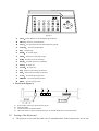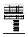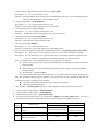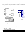
1
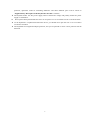
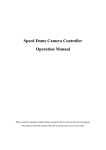
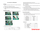
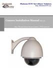
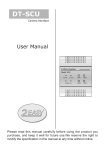
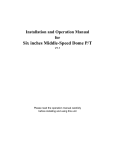
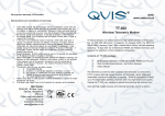
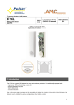
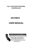
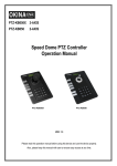
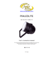
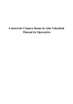
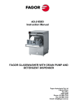
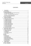
Speed Dome Camera Controller Operation Manual Please read this operation manual before using this device and use the device properly. Also, please keep this manual with care to ensure easy access at any time. SAFETY PRECAUTIONS CAUTION RISK OF ELECTRIC SHOCK. DO NOT OPEN! CAUTION: TO REDUCE THE RISK OF ELECTRICAL SHOCK, DO DOT OPEN COVERS. NO USER SERVICEABLE PARTS INSIDE. REFER SERVICING TO QUALIFIED SERVICE PERSONNEL The lighting flash with a arrowhead symbol, in an equilateral triangle, is intended to alert the user. There is uninsulated “dangerous voltage” presence near by the product's enclosure which may be risk of to persons . The exclamation point within an equilateral triangle is intended to alert the user to reference of the important operating and maintenance (servicing ) instructions . THE PRODUCT CODE MARKED ON THE BOTTOM COVER. PLEASE FILL THE CODE IN THE FOLLOWING BLANK. PLEASE SAVING THIS SPECIFICATION CAREFULLY, SO THAT CHECKING MODEL:________________________________________ PRODUCT CODE:______________________________________ . 1 INDEX I. Summary……………………………………………………………………………3 II. Introduction of Function…………………………………………………………...3 III. Introduction of the Keyboard’s Panel……………………………………………..3 IV. Setting of the Keyboard…………………………………………………………….4 V. Operation of the Keyboard…………………………………………………………5 VI. Installation and Connection…………………………………………………………7 VII. Technical Specifications……………………………………………………………..8 VIII. Points for Attention…………………………………………………………...…..8 2 I. Summary The keyboard controller is used for terminal receivers such as the intelligent Speed Dome and the decoder etc. Taking the EIA/RS-485 electrical interface between the keyboard and the receiver, one keyboard can control as much as 32 speed dome and decoders without driving the bus and the maximum communication distance between the keyboard and the receiver is up to 1.2 km. It’s very easy for operating and setting the Speed Dome Camera. The controller is also to control the terminal receiver to achieve the function of controlling pan/tilt, lens and etc. Main Functions: Set the address range of the dome camera and the decoder:0~64. Control all functions of the dome camera such as Power ON/OFF. To operate the pan/tilt of Speed Dome Camera moving in different speed lever Set or call the points of the dome camera. Altogether 64 preset points can be set. Manually or automatically control the dome camera, and change the settings of particular camera by call the menu of the camera. Manually control the focus, zoom and iris of the camera. II. Introduction of Functions: Select Camera(0~64) Joystick Control Lens Control Control Pan/Tilt direction and speed of the Speed Dome. Control the focus, zoom and iris of the camera. Operation of Preset Position (1~64) Set Preset Position Call Preset Position Operation of Cruise Track(1~6) Run Cruise Track Automatic Horizontal Scan Control of dome (including speed and direction of scan) Self-Learning Track of Intelligent Speed Dome Function Setting of Menu of Speed Dome Direct Control on Decoder III. Control front devices such as the decoder etc. Introduction of the keyboard Panel 1. The Sketch of the Front Panel and Description of Buttons (Figure 1) There are speed joystick, buttons and nixie light on the front panel of the control keyboard. The display is used to show the address of the speed dome as well as the number inputted. The joystick controls the upward, downward, leftward and right ward speed motion of the speed dome. The description of buttons is as follows: 3 MENU Figure 1 z CAM:Select address of the intelligent Speed Dome . z MENU:Auxiliary control buttons. z AUTO:To control auto-horizontal rotation for pan/tilt. z CLEAR: To clear inputted data z 0-9: Number key z WIDE:To a wide angle. z TELE:To turn to a telescopic range. z FAR:To make focus far manually. z NEAR:To make focus near manually. z OPEN:To open iris. z CLOSE:To close iris. z ON:Switch on the setting of function. z OFF:Switch off the setting of function. z CALL:To call the preset position. z PRESET:To set the preset position. z SHOT:To call cruising track. 2. Rear Panel (Figure 2) A B D C DC12V OUT GND RS485 + + - A. Power input connector: input DC12V power. B. DC12V Output. C. Communication connector RS485: D. ID-Code switch: Used to set the protocol in use and the baud rate of communications. IV. Setting of the Keyboard a) The protocol in use and the baud rate of communication of the keyboard are set by the 4 ID-Code in Figure 2. DIP1-DIP4 are used to select type of the communication protocol as per following table Setting of default Baud Rate State of ID-CODE Type of Protocol DIP1 DIP2 DIP3 DIP4 DIP5 DIP6 A01 OFF OFF OFF OFF ON OFF NEON ON OFF OFF OFF OFF ON B01 ON OFF OFF OFF OFF ON SAMSUNG ON OFF OFF OFF OFF ON Santachi OFF ON OFF OFF OFF ON PELCO-D ON ON OFF OFF OFF OFF OFF OFF ON OFF ON OFF OFF ON ON ON ON OFF OFF ON Setting of Protocol Type PELCO-P/4800Bps PELCO-P/9600Bps HUNDA600 b) DIP5 and DIP6 are used to select the baud rate, shown as following table(DIP7 and DIP8 are not used): Status of ID-Code DIP5 DIP6 2400bps OFF OFF 4800bps ON OFF 9600bps OFF ON 19200bps ON ON Baud Rate c) DIP1 DIP2 DIP4 Some of the ID-Code of the protocols are set as follows: B01/9600Bps NEON /9600Bps PELCO-D/2400Bps PELCO-P/4800Bps PELCO-P/9600Bps HUNDA600/9600Bps V. DIP3 ON 1 2 3 4 5 6 7 8 ON 1 2 3 4 5 6 7 8 ON 1 2 3 4 5 6 7 8 ON 1 2 3 4 5 6 7 8 ON 1 2 3 4 5 6 7 8 ON 1 2 3 4 5 6 7 8 Operation of the Keyboard 5 DIP7 DIP8 1. Select Address of Speed Dome Camera /Decoder:[N]+[ CAM] Description:N –– No. of camera from 0 to 64 Function:Select the address of the camera to be controlled. When the value N is in conformity with the address of the speed dome, it will be under control. 2. To set preset position:[N]+[ PRESET] Description:N –– No. of preset position from 1 to 64. Function:Store current position and refer it as No. N position. 3. Call the Preset position:[N]+[ CALL] Description::N –– No. of preset position from 1 to 64. Function: Transfer the camera to the position of No. N preset position. 4. Cancel the Preset position: [N]+[CLEAR] Description:N –– No. of preset position from 1 to 64. Function:Delete the No. N Preset position stored. 5. Tour the Track:[N]+ [SHOT] Description:N –– No. of the track from 1 to 6. Function:Tour the No. N track and stop tour by pushing the joystick. 6. To turn on Auto Pan (Operation of NEON、SAMSUNG Protocol):[AUTO]+[P1]+[ON]+[P2]+[OFF] Description:P1 –– the starting scan No. of preset point from 1 to 64, which should be set already. Description:P2 – the ending scan No. of preset point from 1 to 64, which should be set already. If P1 = P2 or P1 and P2 are coincided, the speed dome will make scan in range of 360°. Note:① For PELCO-D、PELCO-P Protocol the way of operation is as follows: Set the starting scan position: Transfer the Speed Dome to the starting scan position, operation [AUTO]+[ON] Set the ending scan position: Transfer the Speed Dome to the ending scan position,operation [AUTO]+[OFF] Run Auto Pan:[AUTO]+[SHOT] ②Auto Pan operation takes the following parameters. You must set these parameters before using a Auto Pan command to begin the scan operation. You can use the scan stop command ot PT scan stop command to stop the scan. Setting scan condition. z Auto Pan Position(First specify position, second specify position) z Auto Pan Speed and Direction 7. Stop Auto Pan:[AUTO]+[OFF]( Only A01、B01 Available) or push the joystick to stop scan 8. Control the zoom of the Camera:[WIDE]/[TELE] 9. Control the Focus of the Camera:[FAR]/[NEAR] 10. Control the Iris of the Camera:[OPEN]/[CLOSE] 11. Auxiliary Control of the Camera:By combination of [MENU] and [ON], [OFF] buttons, you can set some data of the camera, and functions are listed as follows(operations of NEON Protocol): No. of Value N Definition of Keyboard Operation Control Object power supply/reset [MENU]+N+[ON] [MENU]+N+[OFF] Power ON/OFF Switching Recover Initial Values of Camera 0 Camera control 1 Back Light Compensation ON OFF 2 Zero Illumination (refer to function of camera) ON OFF 6 3 Menu/Display (refer to function of camera) ON OFF 4 Digital Zoom ON OFF 5 Reserved 6 Focus Automatic Manual 7 Iris Automatic Manual Automatic Manual Indoor Mode Outdoor Mode ATW Mode One Push WB Color Black & White < 180°, low speed > 180°, low speed < 180°, middle speed > 180°, middle speed < 180°, high speed > 180°, high speed Start Programming End Programming Run Move joystick to stop 8 9 White Balance Mode(WB) 10 11 Black & White/Color Switching 12 14 Set Auto Pan (Only conditions for scan. If start scan, operate as Item 6 in this paragraph) 15 Reserved 16 Reserved 17 Self-learning programming 18 Control of self-learning of track 13 of track z z For different camera, control functions in the list could be different. For the camera with the menu, switch ON/OFF the menu by “[MENU]+[3]+[ON]”, and switch ON/OFF the OSD by “[MENU]+[3]+[OFF]”. In case the camera has the menu and the menu is ON: 1. Select the item on the menu by buttons [WIDE]/[TELE] to scroll the cursor up or down; 2. Chang the status of the selected item on the menu by buttons [FAR]/[NEAR]; 3. Switch OFF the menu as per operations in the list after the menu is set. z Take care of differences between the Menu of Speed Dome and the Menu of Camera. For the speed dome with the menu, enter the menu by “[64] +[CALL]” and basic operations are as follows: 1. Call No.64 preset point to open the main menu by the control keyboard. 2. When the menu appears on the screen, move the cursor to the item you need to set by “TILT UP” and “TILT DOWN”, and enter the settings of the item to make change by “PAN LEFT” and “PAN RIGHT”; 右 3. Speed up operation of the joystick after keeping it 上 for one second in one direction. 4. All settings of the menu could not be lost even power failure occurred; 下 5. Operations under special case can be referred on the description of the menu of the ball machine. 12. Use the Joystick to Control the Speed Dome Camera: Figure3 You can use the speed joystick to control the Pan/Tilt direction and speed of the dome of the camera randomly. The speed of pan/tilt is decided by the angle of the joystick you operated (Figure 3). Change the tilting angle of the joystick you can adjust the speed evenly and the camera can be focused automatically in the course of scan to keep images being distinct. 上 左 右 下 低速度 高速度 VI. Installation and Connection Attention: Please read the operation manual of the keyboard and the speed dome carefully before 7 左 connecting wires. Any incorrect connections can cause permanent damage of the device. When connecting wires, first switch off the power supply of all devices. The communication wires between devices should be shielded twisted cable. When installing cables they should be far away from high voltage lines or other possible interference circuits as can as possible. 1. Connections of the keyboard controller controlling multiple speed dome cameras(figure4) 2.Connections between the keyboard and the speed dome camera(Figure5) T+ T- 1 2 3 4 5 6 7 8 A LM A LM D C IN GND R+ RV ID E O V ID E O + D O M E SPEED 1 A LM 1 A LM 2 3 D C IN GND 4 R+ 5 R6 V ID E O 7 V ID E O + 8 DO M E SPEED N MENU Figure5 Figure4 VII. Technical Specifications: Communication between Speed Dome Camera and Controller:Port to multi-port and half duplex function. Communication connector: RS-485. Baud Rate of Communication:Four baud rates i.e. 2400Bps, 4800Bps, 9600Bps and 19200Bps. Distance of Communication:1200 M in maximum Power Supply:500 mA(the input voltage of power supply is variable for power supply’s specification) Size: 188 × 97 × 70(mm) Weight:0.5 Kg Number of Controlled Speed Dome Camera up to 32. VIII. Points for Attention: Please read the operation manual of the keyboard carefully before using it. The operation manual is mainly focused on all functions of B01 Protocol. For other different 8 protocols, operations could be something difference and those different parts will be listed on “Supplementary Description of the Keyboard Controller” in details. The keyboard takes 12V DC power supply. Please confirm the voltage and polarity before the power supply is switched on. Do not place the keyboard under the rain or on wet place so as to avoid short circuit or electrical shock. As the keyboard is a sophisticated electronic device, you should never open the case so as to avoid the occurrence of trouble. The keyboard has integrated multiple protocols, and you are pleased to select correct protocol and the baud rate. 9