1
A Mobile Robotics Development Platform
by
Karl E. Keppeler
Submitted to the Department of Electrical Engineering and
Computer Science in Partial Fulfillment of the Requirements
for the Degree of Master of Engineering in Electrical
Engineering and Computer Science at the Massachusetts
Institute of Technology
May 28, 1996
Copyright 1996 Karl E. Keppeler. All rights reserved.
The author hereby grants to M.I.T. permission to reproduce
distribute publicly paper and electronic copies of this thesis
and to grant others the right to do so.
Author
-
·· --
·
Departnn{'of Electrical Engineering and Computer Science
May 28, 1996
Certified by
"ichard D. Thornton
Thesis Supervisor
Accepted b3
F. R. Morgenthaler
Chairman, Dkpartment Committee on Graduate Theses
OF TECNIL..;G'
SEP 17 1996
LIBRARIES
A Mobile Robotics Development Platform
by
Karl E. Keppeler
Submitted to the Department of Electrical Engineering and
Computer Science
May 28, 1996
In Partial Fulfillment of the Requirements for the Degree of
Master of Engineering in Electrical Engineering and
Computer Science
ABSTRACT
The field of mobile robotics has evolved a great deal since its early days. In the beginning,
people were happy to get a control circuit to make a robot move. Now people are doing
sophisticated work in robot navigation and programming. People who have a plan for an
advanced navigation scheme often need a robot with a powerful computer and rarely have
the time or desire to build one from scratch in order to test their ideas. The Mobile
Robotics Development Platform was designed for just such a purpose.
The robot described in this paper is a solid basis for the development of advanced robotic
concepts. As presented, the robot has an 80386 processor core and 1 Mbyte of memory
for computing. It has a solid drivetrain and a microcontroller to handle low level motor
control. And it has an expansion bus which is compatible with most 16 bit ISA cards.
Thesis Supervisor: Richard D. Thornton
Title: Professor of Electrical Engineering
TABLE of CONTENTS
5
1.0 Introduction-..................................................................................................
.................
1.1 Design Considerations............................................
1.2 Possible Additions ......................................................................
2.0
2.1
2.2
2.3
2.4
.................
. .........................
6
7
...................................... 8
Mechanical Construction ................. .........
Chassis Design, Layout, and Construction ........................................................ 9
......... 11
Motor Requirements and Selection Process...................
Drivetrain Description.................................................. 14
........ ...................... 15
Shaft Encoder Construction...............................
.
..............................
3.0 Power Electronic Design...........................
..................................
3.1 Power Supply ...................
............................
3.2 Motor Drive...............................
...... .......
3.2.1 Concept of PWM ................................ ................................
3.2.2 Circuit
17
17
18
19
20
4.0 Control E lectronics .............................................................................................
4.1 Description of the Inte1386 Board...................................................................
4.2 87C51FA M icrocontroller............................................................
........................
4.2.1 Overview .......................................................................................................
4.2.2 Connection..............................
............
................
24
25
26
26
28
5.0 Control Softw are ...............................................................................................
31
5.1 Inte1386 Softw are................................................................
........................
5.2 87C51FA Software....
..............
....................................................
5.2.1 Interface with Inte1386.................................................
5.2.2 Motor Control and Feedback Design ............................... .......................
31
33
33
34
6.0 Conclusions ......................................................................
40
7.0 A cknow ledgm ents..........................................................................................
.... 42
8.0 B ibliography ..................................................................................................
43
9.0 Appendix A 8751 Motor Control Program ................................................
44
LIST of FIGURES
Figure 1. Exploded View of Chassis ........................................................................
.......
Figure 2. Assembled View of Chassis-....----------...................--
......
Figure 3. M otor and Shaft Encoder.........................................................................
Figure 4. Power Supply Schematic .............................
.........
10
11
16
...................... 18
Figure 5. Some PWM Waveforms....................................................
20
Figure 6. Motor Drive Circuitry...................................
22
Figure 7. 87C51FA Connection.............................................
.................... 30
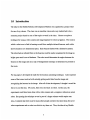
1.0 Introduction
The idea for the Mobile Robotics Development Platform was sparked by a project I did
for one of my classes. The class was on machine vision and every student had to do a
semester project based on one of the topics covered in the class. I chose to explore a
technique for using a video camera and image digitizer for robot navigation. The room in
which a robot was to find its bearings would have multiple infrared beacons, each with a
known location in 3 dimensional space. Each beacon flashed with a distinctive pattern.
The robot had an infrared filter so the beacons could be easily recognized in the image as
bright spots amid a sea of darkness. The robot would determine the angles between the
beacons in the image and use a type of triangulation technique to determine its position in
the room.
For my paper, I developed the math for the location calculating technique. I also explored
some of the issues involved with actually getting useful data from the image and
recognizing the beacons in the image. After all of that development, I thought it would be
fun to try out the idea. Of course, there was one hitch: no robot. In this case, the
experiment could have been done with a video camera and a computer, without an actual
robot. But putting the technique to use in part of a larger scheme would require one.
Also, I realized that there must be many other people out there who have ideas for novel
robot experiments and no robot on which to try them out. Thus, the idea of my Mobile
Robotics Development Platform was born. I set out to build a solid basis to make it easy
for people to perform robotics experiments.
1.1 Design Considerations
The first step in designing a useful platform is to develop constraints for the project. One
must determine which features are necessary for a useful project and which ones simply
create unnecessary work with minimal gain. One of the first requirements set forth was
the need for a fast, modern processor, with a respectable amount of memory (MB range).
Given the state of robot development today, most robotics experiments will be fairly
sophisticated. This means that a processor needs to be able to handle floating point math
and must be relatively fast. Large memory is required for storing maps of rooms, large
control programs, or data to be processed. If a processor is to use video data, it must be
able to store and process thousands of bytes of data in a timely manner. If it takes too
long to process an image, then the movement of the robot is hampered by navigation
overhead.
In addition to a fast processor, the control board needs expansion capability. The
processor needs to be able to sense the robot's environment in order to interact with it in a
meaningful way. For example, to use video data, a processor needs to be able to interface
to a video digitizer board. The computer may also need to gather information from touch
sensors, light sensors, or ultrasonic rangers.
Beyond the control computer, the robot has other requirements. It should be entirely self
contained. It should have a battery for power and power supplies to regulate the voltage
supplied to the computer circuitry. It should have built in capability to control its drive
motors and to collect distance and speed feedback information from them. The control
circuitry of the robot should be able to regulate the robot's speed and monitor its progress
with minimal control overhead visible to the programmer. The robot should be able to
carry enough weight to move itself and whatever sensors or supplementary computers are
needed.
1.2 Possible Additions
With all of the basic fundamental requirements for the robot in place, there are many
extras which could expand the usefulness and versatility of the robot. The video circuitry
mentioned above could be built into the robot for ease of use. An arm could be added.
An arm would make the robot more useful by allowing it to manipulate objects and
perform meaningful tasks. Sensors for monitoring the environment could be built in.
Practical examples would be touch sensors and rangers around the perimeter of the robot.
2.0 Mechanical Construction
Many of the aspects of the mechanical design are derived the way in which the robot is
expected to operate. For example, there are several possible configurations for the wheels
and power transmission. One possibility is two driving wheels and two steering wheels,
like a car. For robotics, the behavior of such a design turns out to be difficult to model.
The layout that was chosen for this robot is the differential steering configuration. This is,
perhaps, the most common robot configuration. The robot has one driven wheel on each
side. The wheels are driven independently by separate motors. To move the robot
forward, both wheels turn forward. To turn, one wheel reverses. This type of behavior is
easy to model and makes for a more maneuverable robot (Jones, 1993).
It is beneficial to have a round perimeter to the robot. If the robot encounters a narrow
channel, it can turn in place, without having any protrusions hit the wall. Path planning is
simplified because the robot does not have to back up to turn. The robot presented here
does not have a circular perimeter. But, very little of the robot protrudes past the circle
which is centered on the middle of the rear axle and goes around the rear wheels. As a
result, if the robot bumps a wall, it is usually the wheels or the opposite end that hits first.
The robot can usually turn without striking the wall with another part of its body.
The design of this robot is a rugged and stable platform. The chassis is built to protect the
electronics and mechanics inside. The wheels are large and durable in order to handle
rough terrain. The robot is designed to have a wide, stable base and a low center of
gravity. Having such a rugged design allows the person using the robot to ignore many
practical issues which might otherwise complicate the design. For example, the large tires
allow the robot to roll over transitions in the floor, carpet, and small objects on the floor,
all of which might stop a robot with smaller wheels. The user does not have to be
concerned with dealing with stalls caused be small, unforeseen objects. The stability of the
platform allows the robot to roll over uneven ground without danger of tipping over.
Two important challenges involved in designing the robot are the chassis and the
drivetrain. The chassis has to be able to support a great deal of weight from the battery,
motors, and anything the user might add on. It has to protect the electronics inside, and
be economical. The drivetrain has to be able to move and accelerate as much weight as
the robot is expected to carry. It has to be smooth and efficient in order to prevent waste
of battery power.
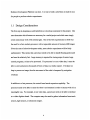
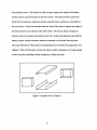
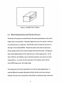
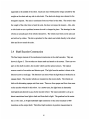
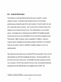
2.1 Chassis Design, Layout, and Construction
The chassis is the basic structure on which the entire robot is built. It provides mechanical
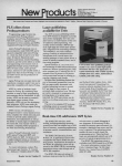
support for the drivetrain, the battery, and the electronics. The chassis is constructed of
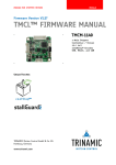
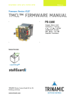
pieces of 1/8 inch sheet aluminum. The pieces are shown in figures 1 and 2 in exploded
and assembled form respectively. The individual pieces are held together at the corners
with machine screws. The material is rigid enough to support the weight of the battery
and the stresses caused by tension on the drive chains. The metal provides a protective
barrier for the electronics, which are entirely contained inside, and forms a removable lid
for easy access. Casters are mounted under the front of the robot to support the weight of
the front end and to move freely as the robot rotates. On the rear, blocks of metal are
formed to bolt to the chassis and clamp the rear axle. Inside, bent aluminum clips hold the
battery in place, and the electronics boards are mounted to the lid and front end piece.
The exact dimensions of the chassis were determined once the bulk of the large parts were
obtained. With all of the parts on hand, the chassis could be designed so it is large enough
to have room for everything, without weighing or costing too much.
i
-#r-
EJ
Figure 1: Exploded View of Chassis
Figure 2: Assembled View of Chassis
2.2 Motor Requirements and Selection Process
The motors for the project are selected based on the desired specifications for the robot's
weight, speed, and acceleration. Permanent magnet DC motors were chosen for their low
cost and good power to weight ratio. Most PM-DC motors develop the most power in
the range of a few thousand RPMs. Because the wheels of the robot turn much more
slowly, gearing must be used to reduce the speed and increase the torque. The high gear
ratios needed (approximately 100:1) require the use of a multi-stage gear box. For the
sake of efficiency and reliability, motors with built in gearboxes were chosen over home
made gearboxes. As a result, the motor selection involves finding a motor with the
correct RPM range, power, and voltage rating.
The requirements for the motor specifications were derived using simple kinetics. It
would be difficult to accurately determine the friction that the motor must overcome.
Therefore, the motors were sized based on their ability to accelerate the mass of the robot
to the desired speed in the desired time. It is assumed that if the acceleration is great
enough, the acceleration force is much greater than the friction force, and the friction
force can be neglected. Also, the desired performance characteristics were chosen
arbitrarily, so they are not critical.
The chosen performance specifications were:
Max Speed:
3 ft/sec
Gross Weight:
120 lb
Time to reach max speed:
1 sec
Wheel Diameter:
8 inch
Calculations:
Acceleration = Max Speed / Time to reach max speed
Acceleration = 3 ft/sec 2
Mass = Weight / g
Mass = 3.75 Slug
Accelerating Force = Weight * Acceleration
Accelerating Force = 11.25 lb
Torque = Accelerating Force * Wheel Radius
Torque = 45 inch*lb = 720 oz*in
Torque at each wheel = 360 oz*in
Rotational Velocity = Linear Velocity / Circumference
Rotational Velocity = 1.43 RPS = 86 RPM
Therefore, the motors must provide 360 oz*in torque at 86 RPM or an equivalent power.
The wheels are driven by the motor shaft through sprockets and chains. As a result, the
motor must have an output RPM that is fairly close to the desired wheel RPM. An
acceptable RPM range for the motor was determined to be one half to two times the
desired wheel RPM in order to keep sprocket sizes within a 2:1 ratio.
The search for the motors was narrowed to a given torque and RPM range and the voltage
was set to be either 12V or 24V, which could easily be obtained with one or two batteries.
The motors that were finally chosen were 12V models. They have a maximum RPM of 55
and a torque of 480 oz*in at 40 RPM according to the distributor. The sprockets used in
the drivetrain are 32 and 18 teeth. The drive increases the wheel speed by 1.78:1. The
resulting max wheel RPM is 98 and wheel torque is 270 oz*in. The speed is a bit higher
than the desired maximum, but given friction in the system, it will probably not reach the
maximum. The torque is a little lower than desired, but because it is not the stall torque,
the motor could actually produce more. Also, the torque is 75% of the arbitrarily chosen
desired value, so the performance will not be significantly reduced.
2.3 Drivetrain Description
The basics of the drivetrain are mentioned above in the motor specification section. The
motor has a built in gearhead to reduce the RPM and increase the torque. The motor
drives the wheels through a sprocket and chain setup. The axles for the rear wheels could
have either been live axles or dead ones. Live axles turn. like those are a car, dead ones
do not. A dead axle was chosen for this robot because the motors have to be able to turn
independently in order for the robot to turn. With live axles, there would have to be two
separate axle halves, each independently supported. The result is that the axle is
supported in the middle of the robot. Each axle must withstand the torque created by the
weight on the robot and any side to side loads. The dead axle design was chosen for the
strength it imparts. The axle is continuous from one wheel to the other. The result is that
the weight of the robot tries to bend the axle, but does not torque the mounts. Also, side
to side loads are not a problem because the axle is clamped in place. The bearings for the
wheels are actually part of the wheels themselves. The wheels turn freely on the axle and
are held on by collars. The drive sprockets for the wheels are bolted directly to the wheel
hubs and do not touch the axles.
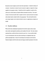
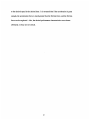
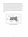
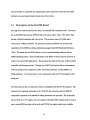
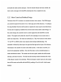
2.4 Shaft Encoder Construction
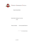
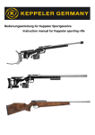
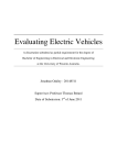
The final major element of the mechanical construction is the shaft encoders. They are
shown in figure 3. The encoders are home made and attach to the motors. There are two
parts to the shaft encoders, the encoder wheels and the optical sensors. The optical
sensors consist of an emitter and detector pair. The light from the emitter is direct at the
detector across a small gap. The detectors can sense when the light beam is broken by an
opaque object. The encoder wheels are mounted on the motor shafts. The wheels are
disks with alternating opaque and clear areas. There are four opaque and four clear areas
on the encoder wheels for this robot. As a motor turns, the light beam is alternately
interrupted and allowed to pass by the encoder wheel. The microcontroller is set up to
detect transistions from light to dark and from dark to light. The gearhead on the motor
has a 110:1 ratio, so 8 light-dark/dark-light transitions on the motor translate to 880
transitions on the output shaft. Therefore, high resolution in position measurement is
possible. Because of the sprocket gearing, the 880 pulses per output shaft rotation
translate to 497 pulses per wheel revolution. With a wheel circumference of 25 in, the
robot moves 0.05 inches per pulse. Therefore, the robot can monitor its position within
0.05 inches. Using a 16 bit number to represent the number of counts to move (i.e.
distance), the robot can move 276 feet with 0.05 inch resolution in one command. Of
course, error will become a factor as the wheels slip slightly or the ground becomes
uneven.
Encoder Wheel
M
rbox
Optical
Sensor
Figure 3: Motor and Shaft Encoder
3.0 Power Electronic Design
When one thinks of designing a robot, probably the first things that come to mind are
mechanical construction and the computer design. One design aspect which may be easily
neglected, but is extremely important is the power electronics. The two specific concerns
are the power supply for the system and the motor drive circuitry.
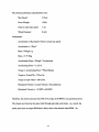
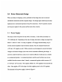
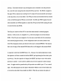
3.1 Power Supply
The source of all of the power for the robot is its battery. In this robot, the battery is a
12V, 26AH gel cell. Depending on the state of charge, the battery voltage can range from
about 11 volts to 14 volts. It is easy to regulate a +5V supply from the battery, any of
several common regulators may be directly attached. But, the computer boards need
+12V and -12V supplies as well. While converters can be designed to convert the battery
voltage to the desired voltages, there were several constraints influencing the design. A
converter could be built from scratch, but it would be difficult to build and not as reliable
as a commercial product. A commercial product could be used, but there was not one
available from the sources at hand. Instead, a commercial regulator which converts +5V
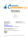
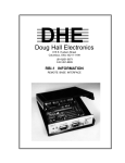
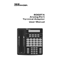
to +12V and -12V was used. Two separate LM323 3A, +5V regulators were used for the
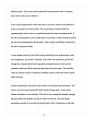
robot. One supplies +5V for the logic, the other supplies power to the 12V regulator.
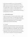
The schematic of the power supply is shown in figure 4.
+5V
+12V
Battery
12V
-12V
GND
Figure 4: Power Supply Schematic
3.2 Motor Drive
The most complicated power electronics circuitry in the robot is the motor drive. The
drive circuit must enable a 5V, low current signal from the microcontroller to control a
12V motor which may draw up to 5A. The microcontroller drives the motors with a pulse
width modulation (PWM) signal through an H-bridge. The motor scheme used in the
robot is a switching technique, as opposed to a linear technique. In a linear speed control
technique, the power transistors supply current to the motor while dropping a significant
portion of the supply voltage. Linear regulators are not very good for this type of design
because they waste a great deal of power. A large percentage of the battery energy is
wasted as heat, resulting in shorter battery life and more heat to get rid of. Switching
regulator, like the PWM H-bridge are much better for this application. In switching
schemes, the power transistors are either completely on or completely off. When they are
off, the current flowing through them, and therefore the power they dissipate is nearly
zero. When they are on, the only voltage drop is the small drain to source voltage, which
also results in little power loss. While some power is wasted during the switching
transitions, switching motor drives are, as a whole, much more efficient than linear ones.
3.2.1 Concept of PWM
The H-bridge applies the full battery voltage to the motor in either the positive or negative
direction by turning on one of two pairs of transistors. The the bridge switches the motor
voltage between positive and negative at a constant rate, which is much faster than the
time constants of the mechanical system. Because the switching is much faster than the
mechanical system can respond, the motor speed only depends on the average value of the
voltage across its terminals. The controller varies the average value of the voltage by
varying the duty cycle of the switching waveform. If the waveform is positive for more
than half of the cycle, the average voltage will be positive. If the waveform is negative for
more than half of the cycle, the average is negative. It the voltage is positive for a fraction
D of the switching period and negative for a fraction (1-D) of the switching period then
the average voltage can be obtained through integration. Vavg = +V * D + (-V) * (l-D) =
2*V*(D-0.5). If D = 0, Vavg = -V; if D = 1, Vavg = V; and if D=0.5, Vvg = 0. Varying D
from zero to one gives an average voltage anywhere from -V to V, where V is the battery
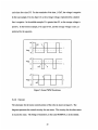
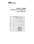
voltage. Figure 5 shows examples of three switching waveforms. The solid line
represents the motor voltage. It swings between the positive battery voltage and the
negative of the battery voltage. The switching period in this example is time T. Because
D represents the fraction of the time that the signal is positive, the positive portion of the
cycle lasts for a time DT. For the remainder of the time, (1-D)T, the voltage is negative.
In the top example, D is less than 0.5, so the average voltage, represented by a dashed
line, is negative. In the middle example, D is greater than 0.5, so the average voltage is
positive. In the bottom example, D is equal to 0.5, and the average voltage is zero, as
predicted by the equation.
Figure 5: Some PWM Waveforms
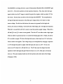
3.2.2 Circuit
The schematic for the motor control portion of the robot is shown in figure 6. The
diagram represents the control circuitry for one motor. The circuitry for the other motor
is exactly the same. The bridge of transistors, in this case MOSFETs, is in the middle.
The MOSFETs are being driven by a pair of International Rectifier IR2110 MOSFET gate
driver IC's. The drivers perform several important functions. First, they allow the logic
signal, which is in the 5V range to control the gate drive signals, which are about 12V for
this circuit. Second, they are able to drive the high side MOSFET. The complication in
driving the high side transistors is that their gate voltage needs to be relative to their
source voltage. For the low side devices, the source is at ground, but for high side
devices, the source is floating. On the left side of the bridge, Q1 is the high side transistor.
When Q1 is on and Q2 is off, Ql's source is near the positive supply voltage. When Q1 is
off and Q2 is on, Q 's source is near ground. The drive IC's are able to take a logic input
which is relative to ground and use it to control the floating gate drive. Finally, the driver
IC's are able to supply 12V above the high side source, which may be at 12V at the time
when it needs to be applied. This voltage step up is accomplished by charging a capacitor
to 12V through the positive supply while the high side source is at OV. For Q1, the
source is at OV when Q1 is off and Q2 is on. The IC then uses the charge from that
capacitor to drive the high side gate when the source is at 12V, when Q2 is off and Q1
turns on. The same situation holds true for Q3 and Q4 on the other side of the bridge
(Clemente, 1990).
Figure 6: Motor Drive Circuitry
The schematic also shows the logic which controls the gate drive signals. The control
signals are pulled up by 10K ohm resistors connected to the +5V supply. The pull-up
resistors are required because the MOSFET driver IC's require higher current than TTL
ICs can source. The controller outputs a PWM signal, which switches on and off at high
frequency to drive the bridge. It also supplies an enable signal to turn the motors on and
off. The inverter insures that the low side and high side transistors are always in opposite
states. If one is on, the other is off. This insures that the 12V supply is never shorted to
ground through the two devices, a condition known as "shoot through". The enable signal
and XOR gates determine whether the right side transistors switch on and off in phase
with the left ones or 180 degrees out of phase with them. It the right side switches out of
phase with the left side, current will flow out the positive supply and through the motor,
causing the motor to turn. If the right side switches in phase with the left side, the motor
is always shorted to itself and no voltage is applied, effectively turning the motor off.
4.0 Control Electronics
Now that there is a motorized chassis and the motor drive to control it, a control
computer is needed. As described in the introduction, there are several desired
specifications governing the design of the control computer. It must be modern, fast, and
have a respectable amount of memory. Also, it must be able to control the motors in the
background, with minimal effort for the user. The resulting design is a two controller
system. At the higher level is a board based on the Inte1386' EX embedded controller.
The processor has the core of an Intel 80386 as well as several built in peripheral circuits.
The board has 1 Mbyte of memory, which is expandable to 16 Mbytes. It also has a
connector which is compatible with the industry standard 16-bit ISA bus. The controller
board can run software written for an IBM PC compatible computer or use its own
operating system.
On the other end of the control story is an Intel 87C51FA microcontroller. This is an 8 bit
microcontroller core with built in peripherals and memory. The microcontroller is used
for the low level control of the motors. The Intel386 board sends commands to the 8751
over a serial link. The 8751 then controls the motors to carry out the specified instruction
and reports back to the Inte1386 when it has completed its job or failed. The
1 1Inte1386
is a trademark and iRMX is a registered trademark of Intel Corporation
microcontroller is responsible for regulating the motor speed with a shaft encoder based
feedback loop and monitoring the distance the robot travels.
4.1 Description of the Inte1386 Board
The high level control board for the robot is an Inte1386 EX evaluation board. The board
has an Inte1386 EX processor, ROM, RAM, and various "glue" chips. The "glue" chips
include a DRAM controller and a bus driver. The processor runs at 25 MHz and is
connected to 1 Mbyte of RAM. The processor itself has an 80386 core and all of the
capabilities of the 80386, including multitasking support (Inte1386 Hardware Reference,
1994). The board can run DOS software or it can run multitasking software with its
iRMX operating system. Some modifications to the BIOS or drivers may be necessary in
order to run some DOS applications. The processor has built in I/O ports, UARTs, DMA
controller, and interrupt control. Through one UART, the board is able to communicate
with a terminal or host computer in order to download software to Flash ROM or to
debug programs. At the same time, it can communicate with the 8751 through the other
serial port.
The board has one pair of connectors which is compatible with the PC/104 standard. The
connectors are logically equivalent to the 16 bit ISA bus, allowing cards for IBM PC
compatible computers to be attached if mating connectors are provided. The restrictions
are that there is no -5V supply, only one (jumper selectable) DMA channel may be used at
once, certain IRQ lines may not be used, and PC/104 bus master mode is not available.
Another connector on the board allows easy access to the rest of the Inte1386's
capabilities, which are not part of the ISA bus (Inte1386 Evaluation Board, 1994). In
addition to DOS software, the board will run programs written in C and compiled on any
of several popular compilers. The ability to use a high level language makes the board
very flexible and easy to use. Because the microcontroller handles motor control,
commanding the robot to move is as easy as sending a move command, the desired speed,
and the desired distance over the serial port.
4.2 87C51FA Microcontroller
The 87C51FA microcontroller, 8751 for short, is the workhorse of the robot. It handles
all of the low level control of the motors. It uses its PWM outputs to drive the motors
and its Counter/Timer inputs to measure the motor speed and distance traveled. The 8751
communicates with the Inte1386 through its serial port. It receives commands for
controlling the motors, then performs the desired operations.
4.2.1 Overview
The 87C51FA is an almost entirely self contained microcontroller system. It has 3 timers,
a programmable timer/counter array with 5 counters, a serial port, an interrupt controller,
data RAM, and program EPROM, all on one IC (Intel MCS51, 1994). The timer/counter
array is the most important part for the robot. It has five counters, each driven from a
common timebase. The time can either come from the microprocessor clock, divided by 4
or 32, one of the timers, or an external source. Each counter can be configured for
compare/capture, software timer, high speed output, or pulse width modulator. One of
the counters may also be used as a watchdog timer. The program must continually reset
the watchdog timer. If the timer reaches a specified count, it is assumed that the program
has gotten stuck because of some unforseen condition, and the processor is reset. The
robot uses two of its counters as compare/capture modules for measuring motor speed
and two as PWM outputs for controlling motor speed.
The compare/capture modules operate as follows. There is one counter for all of the
timers, which continuously counts in a 16 bit register. For each compare/capture module
there is a separate 16 bit counter. A transition on a counter's input bit latches the value
from the main counter into its own register and triggers an interrupt. The interrupts are
maskable, but they are set to active for this application. The module can be triggered by a
rising edge, a falling edge, or both. For the robot, it is set to trigger on both, giving twice
the resolution of just triggering on one. The trigger input is the output from the shaft
encoder. As the motor rotates and the light beam is allowed to pass or is blocked, the
signal goes high and low, causing rising and falling edges on the counter inputs. Each
rising or falling edge causes another interrupt. The interrupt service routine measures time
between consecutive interrupts and compares it to the expected time for the desired speed.
If the time is more or less, the motors are sped up or slowed down accordingly.
Two modules are used as PWM outputs for the motors. The PWM counters act as 8 bit
counters. They are run off of the common timer for the modules and consequently have a
fixed rate of operation. The program loads a register in the timer with an 8 bit value, the
desired PWM duty cycle. The output pin is low at the beginning of the cycle and goes
high when the count value reaches the value in the register. This process repeats every
cycle. The motor average voltage can then be regulated simply by changing the number in
the register.
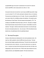
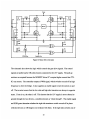
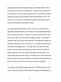
4.2.2 Connection
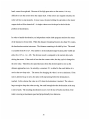
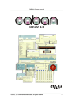
The connection of the 8751 in the circuit is very simple. As mentioned above, it is almost
entirely self contained. Simply connecting a crystal, two capacitors, and a reset capacitor
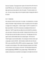
is enough to have a working micro. As shown in figure 7, the 8751 is connected to a 32
Kbyte static RAM IC. On the 8751, the data lines are multiplexed with the lower 8
address bits. The 8751 outputs the lower address bits on the first half of an instruction
cycle, then reads or writes data on the second half. During the first half of the cycle, the
8751 places the lower half of the address on the bus lines. The falling edge of the ALE
signal is used to clock the address lines into an external register. For this circuit, a
74LS374 register is used to hold the address. The ALE signal is inverted in order to give
a rising edge to clock the 74LS374. After the address is latched, the micro will assert
/WR to write to the RAM or /RD or /PSEN to read data or program memory. The RAM
was added to ease development. With a simple shell program, programs may be loaded
over the serial port, stored in memory, and executed. The shell program eliminates the
need for programming an EPROM for every program change. While the RAM is not
needed in the final circuit, it is kept there in case changes are to be made to the low level
software. The RAM will allow easy development and is available in case the processor
has a need for more storage than the internal RAM can provide. The RAM is mapped to
the upper 32K on memory by inverting the A15 output of the microcontroller and using it
as the chip select, /CS, for the RAM. The /WR pin of the microcontroller directly controls
writes to RAM through the /WE pin on the RAM. The /RD and /PSEN signals from the
microcontroller are ANDed together to control the /OE pin of the RAM, causing all reads
to come from the same RAM.
The /EA pin is used to tell the 8751 to run from either internal or external program
memory. In this circuit, it is strapped to Vcc so the boot program is run from internal
ROM. If the /EA pin were strapped to Vss, the micro would fetch all of its instructions
from external program memory. In the configuration used in the robot, fetches to the
lower 8K of program memory are directed to the micro's internal EPROM. The memory
that is out of range of the internal ROM (above 8k) is still mapped to the external RAM.
A capacitor is tied from the RESET pin to Vcc. Because of an internal pull-down circuit,
the capacitor is all that is needed to hold the RESET pin high during the first clock cycles
at power up. Once the capacitor is charged, the RESET pin drops to zero volts and the
processor is started. A reset switch is added across the reset capacitor to allow manual
reset. A toggle switch to ground and a pull-up resistor are added to port 1.7 as a control
input. The shell program uses the input to determine whether to run its boot loader code
or to run the code which it has loaded into RAM. When the user selects the option of
running the code in RAM, the shell program jumps to location FFOOh to run the program.
Interrupts at locations 00xxh are vectored to Ffxxh.
Figure 7: 87C51FA Connection
There are not many other support chips for the microcontroller. The IR2110 MOSFET
drivers are connected to drive the H-bridge. Also 1488 and 1489 line drivers and
receivers are connected to the micro to allow the serial port to communicate with standard
RS232 devices. The detectors for the shaft encoders are Opto-Logic devices. With the
help of a pull-up resistor, they produce a TTL compatible output with no external signal
amplification. Therefore, the shaft encoders connect directly to the inputs of the
microcontroller.
5.0 Control Software
Software for the robot is broken down into two levels. One is the high level control code,
which the end user writes for a specific application. This code takes care of navigation,
path planning, and task organization. The high level code all resides on the Inte1386
board. Commands sent from the high level program to the microcontroller are abstract
commands, like "go forward at some speed".
The other software level is the lower level. Is is handled by the 8751. It gets commands
from the Inte1386 board and breaks them down into the most basic control steps. It tells
the motors to start turning by enabling them and setting a certain PWM duty ratio. It then
monitors the speed and varies the duty ratio to regulate the speed. In some cases, the
microcontroller counts the number of shaft encoder pulses to measure or verify the
distance traveled. One of the highest level functions the microcontroller does is to vary
the desired speed of the motors to allow smooth acceleration and deceleration, rather than
jerky stops and starts, which may induce slipping. It must also regulate the speeds of the
two motors to insure that the robot goes is a straight line when it is supposed to.
5.1 Inte1386 Software
It is difficult to describe the software for the Inte1386 board in much detail because it is
almost entirely dependent on the particular application. The following is a brief example
of what the software might do in one application. One typical use of the robot might be to
deliver mail around an office, following a route which depends on who has is going to
receive mail. The robot might use the video navigation scheme described in the
introduction. The Inte1386 board would have a map of the entire office stored in its
memory. When given input about what mail it is carrying, it would go through the list of
destinations and plan a route around the office that would go to each one. The Inte1386
would then take an image and use the navigation scheme to find its location and heading.
Next, the Inte1386 board would determine how far the robot needs to turn or move
forward in order to follow the desired path. It will then send the turn or move command
to the 8751 and wait for a reply to indicate that the action is finished. The Inte1386 would
then determine the next move to make in order to follow the desired path, and pass it on
to the microcontroller. Occasionally, the robot has to recompute its location, to make
sure there was no slippage in the wheels which would throw off the location reading.
After the Inte1386 establishes the robot's location, it can make corrections to its
preplanned path, as necessary. Also, while following the path, the robot may sense
obstacles, such as people it the way. They might be detected with an ultrasonic ranger.
The Inte1386 board would then have to modify the planned path and give the new
movement instructions to the 8751. Through all of the movements, the 8751 is simply
accelerating and decelerating the motors, regulating their speed, and keeping track of the
distance traveled.
5.2 87C51FA Software
The software for the 8751 is more easily explained, because in general, it will not change.
It is at the user's discretion to change the 8751 program to make it more versatile or more
complicated, but the basic function can be described here. The general tasks of the 8751
are to interface to the Inte1386 board in order to receive commands and to control the
motors
5.2.1 Interface to Inte1386
The easy part of the 8751's job is to communicate with the Inte1386. The 8751 has a built
in serial port, which makes it simple to directly connect the micro to the other board. The
8751 controller basically initializes itself, then waits for interrupts. When an interrupt is
triggered, indicating data in the serial port, the 8751 runs an interrupt handler which reads
the data and decides how to act on it. If the data is a command to move forward, the
8751 will wait until it gets information about the desired speed and distance. Each
command that the Inte1386 sends to the 8751 is similar to an assembly language
instruction. It describes a certian action to be taken. The instructions are always followed
by a fixed number of operands, the number of which depends on the particular instruction.
Once an instruction and its operands have been received, the 8751 will run the motor
control routines. The motor control routines set up the motor outputs, enable the motors,
and enable the shaft encoder interrupts. Once the desired distance has been reached, the
micro sends a message to the Inte1386, indicating that it has completed its task.
5.2.2 Motor Control and Feedback Design
The heart of the 8751's mission is to control the robot's drive motors. The PWM output
can control the speed of the motors over a wide range and in both directions. A technique
for using feedback from the shaft encoders to regulate the motor speed is described below.
For the sake of simplicity, feedback was not used in the current motor control design. In
the current design, the controller recieves control signals from the Inte1386 to run the
motors. The signal can be either the value 65 or 66, meaning to turn on motor zero or
motor one respectively. The values are arbitrarily set. They were chosen to be the letters
"A" and "B" in ASCII to allow easy manual control during troubleshooting. The
command it followed by three bytes: the speed and the high and low bytes of the distance.
The distance is the number of counts on the shaft encoder. As the data is received, it is
stored in the appropriate variables. Once all of the data is in, the controller jumps to a
motor initialization routine. The routine sets the motor speed, enables the shaft encoder
interrupt, and starts the motor. The shaft encoder interrupt routine decrements the value
of the distance counter every interrupt. When the distance counter reads zero, the routine
shuts off the motor and notifies the Inte1386 by sending a 65 or 66 to tell it which motor
finished.
The motor control routines describe above are very simple. It would not be difficult to
add other features. Other commands could be added to the vocabulary. For example, the
Inte1386 could the the microcontroller to stop the motors and return information about
how far it has traveled. There could be a command which does not specify the distance to
be traversed. Instead, the robot continues until instructed to stop.
As mentioned above, a feedback system would be helpful in regulating the motor speeds.
Without feedback, the motor speed is affected by the battery voltage, the load imposed on
the motor, and other undefinable factors. The shaft encoders may be used as speed
feedback, as the basis for regulating the motor speed. They each cause an interrupt in the
microcontroller every time the robot moves forward 0.05 inch. The timer clock is running
at one fourth of the processor clock speed, or 3 MHz. If the motor output shaft is turning
at 60 RPM or 1 RPS, the motor shaft is turning at 110 RPS. At 8 transitions per
interrupt, the micro gets 880 interrupts per second from each motor. This means that
there are 1.14 mS or 3410 counts between interrupts. So, every time the robot moves
0.05 inch, it can tell how long it took and therefore how fast the robot is going, to three
decimal places. When the pulse is received, the controller either increases or decreases the
PWM duty cycle in proportion to the error in the time measured. If the time is too long,
the robot must be moving too slowly. The period of the PWM signal is increased in order
to speed up the motor. The calculations above represent the motor turning as fast as it
possibly could. If the motor is rotating more slowly, the reading is even more accurate,
because there are more counts between pulses.
While the basic feedback scheme seems simple, there are several complications to deal
with. For example, if the motor is stalled, there will never be an interrupt. The pulse
width will never change and the robot will not move. If the motor stalls near the edge of
an encoder transition, vibrations can make it appear as if the motor is rotating very rapidly,
interfering with the operation of the circuit. As an added complication, many of the values
that must be dealt with are 16 bit. The microcontroller is an 8 bit device, and 16 bit
operations can be tricky at times. While all of these factors do not make it impossible to
implement a feedback system, they do present a programming challenge.
The control scheme that the microcontroller implements is currently very simple. The
speed of each motor is unregulated, and depends on the power of the motor to give
consistant speed. In many cases, such a scheme is acceptable. However, one situation in
which problems may arise is when both motors are supposed to be going the same speed,
so the robot travels in a straight line. In general, the motor speeds are well enough
matched that there is not a problem. But, if one motor is so loaded down that it cannot
maintain speed, even and maximum duty cycle, there will be a speed mismatch between
the motors. The robot will not travel in a straight line. The basic approach of
independently regulating the speed of each motor will be insufficient. The microcontroller
has not way of knowing that both motors should be turning at the same speed. If the
robot were set up to travel in a curve, the motors would intentionally be moving at
different speeds. If one motor cannot maintain the expected speed, there is a question
about what the other motor should do.
In the current implementation of the robot, there is no built in solution to the problem of
motors not turning at the desired speed. One can generally avoid the problem by
programming the robot to move at a significant amount less than its maximum speed. If
the robot is programmed to move at half speed, it would take a serious obstacle to prevent
the robot from maintaining the desired speed. Such an object would likely be detected by
the robot's navigation scheme.
A more elegant solution, but one which require considerably more programming, would
be to implement a "go forward" command. If the robot were instructed to go forward
through this command rather than by separately setting both motors to forward, the
controller would know that it must keep them going at the same speed. The controller
could use separate routines to implement a feedback system in which the motors' speeds
affect each other.
Another complication to the motor control scheme is acceleration and deceleration. The
robot is very heavy and consequently cannot instantly change speed. In the current
scheme, acceleration is not controlled. The robot is heavy enough that instantly changing
the pulse width to the desired level does not make the tires slip. The robot simply
accelerates as quickly as it can and the specified pulse width. Deceleration, on the other
hand, cannot be neglected. Because of the high gear ratios on the motors, it is very
difficult to turn the motors from the output shaft. If the motors are stopped instantly, the
robot will try to stop instantly. In most cases, the pins holding the sprockets to the motor
output shafts will be sheared off. A simple scheme was developed to deal with the
problem of deceleration.
In order to handle deceleration, an independent routine inthe program monitors the status
of the distance to be traveled. When the distance remaining becomes less than 512 counts,
the deceleration routine intervenes. The distance remaining is divided by four. The result
is a number from 0 to 127. The number is in the indicated range because pulse widths are
either 0 to 127 or -1 to -128. The division result is compared to the current duty cycle
driving the motor. If the result is less than the current value, the duty cycle is changed to
the new value. Therefore, the speed decreases from the desired speed to zero as the
distance approaches zero. In actuality, a constant, 32, is added to the result before it is
used as the new duty ratio. The reason for changing the value is to set a minimum. If the
ratio is allowed to go to zero, the motor will stop turning before the destination is
reached. In this scheme the value is at 32 when the destination it reached. The value is
large enough to keep the robot moving, but small enough that the deceleration at the stop
is not to harsh. The resulting deceleration occurs over the last 25 inches traveled, if the
robot is moving at maximum speed and proportionally less otherwise.
More sophisticated acceleration control is obviously possible. If a feedback system were
used, the minimum pulse width for deceleration could go to zero, because the robot would
be guaranteed to keep moving. Control of acceleration could be added to smooth out the
starts. In a really complex system, the top speed could be manipulated to account for
acceleration so the average speed would match the desired speed.
6.0 Conclusions
The end result of all of this planning and construction is a very simple, yet rugged robot.
The robot has a strong chassis to protect the electronics inside and provide solid mounting
for any equipment which will be added later. The 87C51FA board provides the capability
for fairly simple low level feedback control of the motors. The microcontroller makes it
easy for the user to drive the motors and control the robot with minimal effort. Through
the feedback system, one can make the robot travel in a straight line at a known speed and
for a specified distance. The robot can just as easily be turned or backed up. The
EPROM in the 87C51FA and the RAM attached to it make it easy for the user to develop
new motor control routines for a custom interface or more sophisticated control. The
8751 has enough extra capacity that it could be connected and programmed to handle
other tasks, in addition to motor control. The 8751 has several I/O ports and timers free
which could at least be used to monitor touch switches or to connect to an A-D converter.
While the robot is rugged and robust, it is very simple. There is plenty of room for
expansion. The end user may use his or her own discretion in adding sensors or actuators.
The robot may be outfitted with an arm or some type of application specific appendage.
The ISA compatible bus on the Inte1386 board makes it easy to add any of a number of
commercially available boards. One could add a video digitizer, a board with multiple AD converters and I/O ports, or even a disk drive controller board.
This robot was designed to be the basis for advanced robotic experiments. It provides a
basic platform, motor control and computing power. Hopefully the next time someone
has an idea for a robotic experiment, they can use this platform to try it out with minimal
effort.
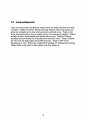
7.0 Acknowledgments
There are several people I should thank, without whom this project may have never been
completed. Thanks to Professor Thornton for being willing to sponsor this project and
giving me invaluable advice about which processors and boards to use. Thanks to Jim
Byrne who transformed me from a complete novice to an experienced machinist. Without
his help, the robot would probably look terrible and run worse. Thanks to Professor
Kassakian and Dave Perrault for invaluable power electronics advice. Thanks to Robert
Irie who wrote the shell program for the 8051 processor. Thanks to Mai Yin for
hounding me to work. Without her I might still be watching TV, thinking about working.
Finally, thanks to my family for their support in all of my endeavors.
8.0 Bibliography
Clemente, Steve and Ajit Dubhashi HV FloatingMOS-Gate Driver IC. International
Rectifier, El Segundo, CA, 1990.
Concurrent Sciences Inc. Soft Scope Debugger. Concurrent Sciences, 1994.
Intel Corporation Inte1386 EX Embedded MicroprocessorEvaluationBoardManual.
Intel, 1994.
Intel Corporation Inte1386 EX Embedded MircoprocessorHardwareReference. Intel,
1994.
Intel Corporation iRMX EMB OperatingSystem User's Guide. Intel, 1994.
Intel Corporation MCS 51 MicrocontrollerFamily User's Manual. Intel, 1994.
International Rectifier IR2110 High Voltage MOS Gate Driver. International Rectifier.
Jones, Joseph L. and Anita M. Flynn Mobile Robotics: Inspirationto Implementation.
A.K. Peters, Wellesley, Mass., 1993.
Kassakian, Schlecht, and Verghese Principlesof PowerElectronics. Addison-Wesley,
Reading, Mass., 1991.
Appendix A 8751 Motor Control Program
; MotorDrv.A51
; Program to handle low level control of the drive motors
; and communication with the control computer
; Karl Keppeler
;5/24/96
;----------------------------------------
-------
$NOMOD51
$INCLUDE (d:\thesis\c5 l\asm\reg51 f.inc)
NAME
MotorDrv
PROG
SER_seg
PCA_seg
STACK
VAR1
SEGMENT
SEGMENT
SEGMENT
SEGMENT
SEGMENT
CODE
CODE
CODE
IDATA
DATA
RSEG STACK
DS
10H
; 16 byte stack
CSEG AT
USING
; reset vector for the processor
; register bank 0
jmp
0000h
0
START
; jump to program
; main body of the program, initializes everything
RSEG PROG
START:
mov
call
mov
mov
mov
mov
mov
SP, #Stack- 1
SERINIT
CMOD, #00000010b
CCAPMO, #01000010b
CCAPM1, #01000010b
CCAPM2, #00110000b
CCAPM3, #00110000b
initialize stack pointer
initialize serial port
set PCA timer mode
set up PWM mode for motor
set up PWM mode for motor
setup counter/timer 2
setup counter/timer 3
mov
setb
mov
mov
mov
mov
mov
mov
mov
CCON, #0
CR
IE,#11010000b
SpeedO, #0
DistHO, #0
DistLO, #0
Speed1, #0
DistH i, #0
DistL1, #0
jmp
Stop
; clear all PCA interrupts
; turn counter on
; enable PCA interrupt and serial int
; initialize speed and distance
; values to zero
Stop:
;procedure to initialize motors
MinitO: mov
add
mov
mov
mov
clr
clr
ret
A, SpeedO
A, #128
DutyO, A
CCAPOH, DutyO
CCAPM2, #0011000 1b
CCF2
P1.1
; get the speed for this motor
; convert to PWM value
; store as current PWM value
; set PWM value in counter
;Enable shaft enc interrupt
; clear shaft encoder interrupt
; enable motor drive
Minit l: mov
add
mov
mov
mov
clr
clr
ret
A, Speedl
A, #128
Duty 1l,A
CCAPlH, Dutyl1
CCAPM3, #00110001b
CCF3
P1.2
; get the speed for this motor
; convert to PWM value
; store as current PWM value
; set PWM value in counter
;Enable shaft enc interrupt
; clear shaft encoder interrupt
; enable motor drive
; Interrupt handler for the shaft encoders
RSEG PCA_seg
USING
1
PCAint:
push PSW
push ACC
mov PSW, #08h
jnb CCF2, Interl
mov
jnz
mov
A, DistLO
Nzer0
A, DistHO
; use register set 1
; save program status word
; save accumulator
; change to register set 1
; if motor 0 bit not set, skip
; motor zero routine
; get low byte of distance for motor0
; if the low byte is not zero, don't
; change high byte
jnz
call
jmp
NdoneO:
dec
NzerO: dec
NdoneO
Done0O
DnO
mov
clr
rrc
jnz
mov
rrc
clr
rrc
add
mov
mov
clr
subb
mov
jb
mov
clr
subb
jnb
mov
add
mov
jmp
DnegO: mov
clr
subb
mov
clr
subb
jb
mov
add
mov
ChDutO:
mov
DnO: clr
jnb
A, DistHO
DistHO
DistLO
; if high byte is also zero, done
if high byte is not zero, decrement
decrement low byte
deceleration routine
Get high byte of dist
A
DnO
A, DistLO
A
C
A
A, #32
DTemp, A
A, DutyO
C
A, #128
ShDuty, A
ACC.7, DnegO
A, Dtemp
C
A, ShDuty
ACC.7, DnO
A, Dtemp
A, #128
DutyO, A
ChDutO
A, #0
C
A, Dtemp
DTemp, A
C
A, ShDuty
ACC.7, DnO
A, Dtemp
A, #128
DutyO, A
; Rotate to decel if high byte is zero or 1
; Skip decel if not near end of travel
; get low byte of dist remain
; Shift down, shift in bit from high
CCAPOH, DutyO
CCF2
CCF3, IntDone
; update PWM duty cycle
; clear shaft encoder interrupt
; if bit for motor 1 not set, done inter
; Shift in 0, shift down one
; set minimum speed when decel
; store new desired speed
; get current speed
; get so pos=fwd, neg=bwd
; save this version
; if current speed is neg, other routine
; get new desired speed
; compare to current speed
; don't do anything if current speed slower
; if current speed faster:
;convert new speed to duty cycle
; update current speed with new speed
; get negative of desired speed from before
; store as new desired speed
; compare to old speed
; don't change if new speed is faster
;get desired speed
; convert to duty cycle
; store as new duty cycle
A, DistL1
Nzerl
A, DistH1
Ndonel1
Donel1
Dn1
; get distance for motor1
; don't change high byte if low is not 0
; get high byte
; if zero, count is done
; decrement high byte
; decrement low byte
; deceleration routine
; same as for motor0
mov
clr
subb
jnb
mov
add
mov
jmp
Dnegl: mov
clr
subb
mov
clr
subb
jb
mov
add
mov
DistHi1
DistL1
A, DistH1i
C
A
Dnl
A, DistL1
A
C
A
A, #32
DTemp, A
A, Duty 1l
C
A, #128
ShDuty, A
ACC.7, DNegl
A, DTemp
C
A, ShDuty
ACC.7, Dn1
A, DTemp
A, #128
Duty 1, A
ChDutl
A, #0
C
A, DTemp
DTemp, A
C
A, ShDuty
ACC.7, Dnl
A, DTemp
A, #128
Duty1, A
ChDutl:
mov
CCAP1H, Dutyl
Interl: mov
jnz
mov
jnz
call
jmp
Ndonel:
dec
Nzerl: dec
mov
clr
rrc
jnz
mov
rrc
clr
rrc
add
mov
mov
clr
subb
mov
CCF3
; clear shaft enc 1 interrupt
ACC
PSW
;restore accumulator
; restore PSW and register set0
DoneO: setb
mov
call
ret
P1.1
; turn motor off
; send char indicating done
Done 1: setb
mov
call
ret
P1.2
Dnl:
clr
IntDone:
pop
pop
RETI
A, #65
SNDCHAR
A, #66
SNDCHAR
; Jump vector for PCA counter interrupts
CSEG AT
0033h
LJMP PCAint
; turn motor off
; send char indicating done
; interrupt vector for PCA
; serial port interrupt handler
RSEG SER_seg
USING
1
Serint:
push
push
mov
jnb
clr
mov
subb
jnz
Waitl: jnb
clr
mov
Wait2: jnb
clr
mov
Wait3: jnb
clr
mov
call
PSW
ACC
PSW, #08h
RI, Sdone
RI
A, SBUF
A, #65
NmotO
RI, Wait1
RI
SpeedO, SBUF
RI, Wait2
RI
DistHO, SBUF
RI, Wait3
RI
DistLO, SBUF
MinitO
save PSW
save accumulator
change to register set 1
if the interrupt is not received
data, don't do anything
clear interrupt signal
get character from serial port
compter to the letter "A"
if not A, it is not for motor0
it is for motor0, wait for next byte
clear interrupt
store next byte, speed
wait for next byte
clear interrupt
store next byte, high distance byte
wait for next byte
clear interrupt
store next byte, low distance byte
initialize motor0
Sdone
; finish interrupt routine
dec
jnz
Wait4: jnb
clr
mov
Wait5: jnb
clr
mov
Wait6: jnb
clr
mov
call
A
Sdone
RI, Wait4
RI
Speedl, SBUF
RI, Wait5
RI
DistH1, SBUF
RI, Wait6
RI
DistL1, SBUF
Minitl
; compare to "B", character for motor1
; if not it, quit
; wait for next byte
; clear interrupt
; store byte, speed
; wait for next byte
; clear interrupt
; store next byte, high dist byte
; wait for next byte
; clear interrupt
; store next byte, low dist byte
; initialize motorl
Sdone: pop
pop
reti
ACC
PSW
;restore accumulator
; restore PSW and reg set 1
jmp
NmotO:
;Jump Vector for serial port interrupts
0023h
CSEG AT
LJMP Serint
; interrupt vector for Serial
RSEG PROG
;Initialize Timer 1 to generate baud rate; fosc=12 mhz, baud rate@2400
SERINIT:
mov SCON,#50h
mov TMOD,#21h
;c/T#=O, mode 2, auto-reload
mov TH1,#243
;baud rate=fosc/(32* 12*(256-thl))
setb TR1
setb
TI
ret
; send a character in A to the serial port
SNDCHAR:
jnb
cldr
mov
ret
TI, $
TI
SBUF, A
RSEG VAR1
DS
SpeedO:
DS
Speedl:
; wait for trans buffer to be empty
; set buffer flag to busy
; put char to write in buffer
Duty0:
Duty 1:
Dtemp:
SHDuty:
DistHO:
DistLO:
DistHi1:
DistL 1:
END
DS
DS
DS
DS
DS
DS
DS
DS