1
9.5.10.2 Termination Signals Protocol Summary
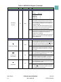
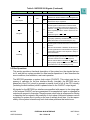
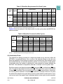
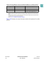
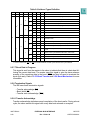
Table 5-2 summarizes how the MPC555 recognizes the termination signals provided
by the slave device that is addressed by the initiated transfer.
Table 9-10 Termination Signals Protocol
TEA
TA
RETRY
Action
Asserted
X
X
Transfer error termination
Negated
Asserted
X
Normal transfer termination
Negated
Negated
Asserted
Retry transfer termination
9.5.11 Bus Operation in External Master Modes
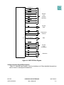
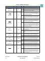
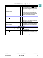
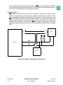
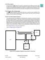
When an external master takes ownership of the external bus and the MPC555 is programmed for external master mode operation, the external master can access the
internal space of the MPC555 (see 6.2 External Master Modes). In an external master mode, the external master owns the bus, and the direction of most of the bus
signals is inverted, relative to its direction when the MPC555 owns the bus.
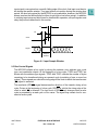
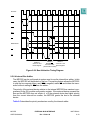
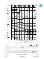
The external master gets ownership of the bus and asserts TS in order to initiate an
external master access. The access is directed to the internal bus only if the input
address matches the internal address space. The access is terminated with one of the
followings outputs: TA, TEA, or RETRY. If the access completes successfully, the
MPC555 asserts TA, and the external master can proceed with another external master access or relinquish the bus. If an address or data error is detected internally, the
MPC555 asserts TEA for one clock. TEA should be negated before the second rising
edge after it is sampled asserted in order to avoid the detection of an error for the next
bus cycle initiated. TEA is an open drain pin, and the negation timing depends on the
attached pullup. The MPC555 asserts the RETRY signal for one clock in order to retry
the external master access.
If the address of the external access does not match the internal memory space, the
internal memory controller can provide the chip-select and control signals for accesses
that belong to one of the memory controller regions. This feature is explained in SECTION 10 MEMORY CONTROLLER.
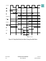
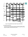
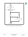
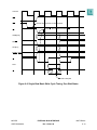
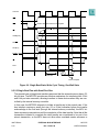
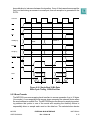
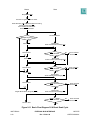
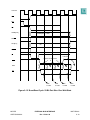
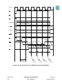
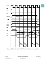
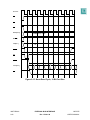
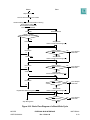
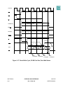
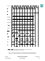
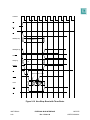
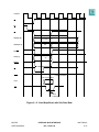
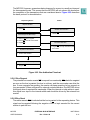
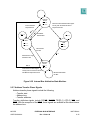
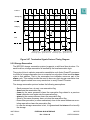
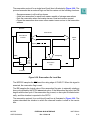
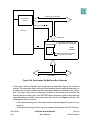
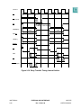
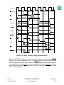
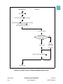
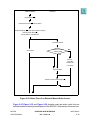
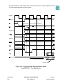
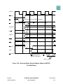
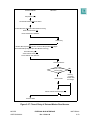
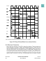
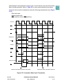
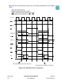
Figure 9-33 and Figure 9-36 illustrate the basic flow of read and write external master
accesses.
MPC555
USER’S MANUAL
EXTERNAL BUS INTERFACE
Rev. 15 Nov 98
MOTOROLA
9-47