1
Application Note
78K0
8-Bit Single-Chip Microcontrollers
Window Watchdog Timer
78K0/Fx2 Series
78K0/Kx2 Series
78K0/Lx2 Series
Document No. U18758EE1V1AN00
Date Published 5 th July 2007
© NEC Electronics Corporation 2007
Printed in Germany
1
Application Note U18758EE1V1AN00
[MEMO]
2
Application Note U18758EE1V1AN00
•
The information in this document is current as of April, 2007. The information is subject to change
without notice. For actual design-in, refer to the latest publications of NEC Electronics data sheets
or data books, etc., for the most up-to-date specifications of NEC Electronics products. Not all
products and/or types are available in every country. Please check with an NEC Electronics sales
representative for availability and additional information.
•
No part of this document may be copied or reproduced in any form or by any means without the prior
written consent of NEC Electronics. NEC Electronics assumes no responsibility for any errors that may
appear in this document.
•
NEC Electronics does not assume any liability for infringement of patents, copyrights or other intellectual
property rights of third parties by or arising from the use of NEC Electronics products listed in this
document or any other liability arising from the use of such products. No license, express, implied or
otherwise, is granted under any patents, copyrights or other intellectual property rights of NEC Electronics
or others.
•
Descriptions of circuits, software and other related information in this document are provided for
illustrative purposes in semiconductor product operation and application examples. The incorporation of
these circuits, software and information in the design of a customer's equipment shall be done under the
full responsibility of the customer. NEC Electronics assumes no responsibility for any losses incurred by
customers or third parties arising from the use of these circuits, software and information.
•
While NEC Electronics endeavors to enhance the quality, reliability and safety of NEC Electronics
products, customers agree and acknowledge that the possibility of defects thereof cannot be eliminated
entirely. To minimize risks of damage to property or injury (including death) to persons arising from
defects in NEC Electronics products, customers must incorporate sufficient safety measures in their
design, such as redundancy, fire-containment and anti-failure features.
•
NEC Electronics products are classified into the following three quality grades: "Standard", "Special" and
"Specific".
The "Specific" quality grade applies only to NEC Electronics products developed based on a customerdesignated "quality assurance program" for a specific application. The recommended applications of an
NEC Electronics product depend on its quality grade, as indicated below. Customers must check the
quality grade of each NEC Electronics product before using it in a particular application.
"Standard": Computers, office equipment, communications equipment, test and measurement
equipment, audio and visual equipment, home electronic appliances, machine tools,
personal electronic equipment and industrial robots.
"Special":
Transportation equipment (automobiles, trains, ships, etc.), traffic control systems,
anti-disaster systems, anti-crime systems, safety equipment and medical equipment
(not specifically designed for life support).
"Specific":
Aircraft, aerospace equipment, submersible repeaters, nuclear reactor control
systems, life support systems and medical equipment for life support, etc.
The quality grade of NEC Electronics products is "Standard" unless otherwise expressly specified in NEC
Electronics data sheets or data books, etc. If customers wish to use NEC Electronics products in applications
not intended by NEC Electronics, they must contact an NEC Electronics sales representative in advance to
determine NEC Electronics' willingness to support a given application.
(Note)
(1) "NEC Electronics" as used in this statement means NEC Electronics Corporation and also includes its majority-owned
subsidiaries.
(2) "NEC Electronics products" means any product developed or manufactured by or for NEC Electronics (as defined
above).
M8E 02. 11-1
Application Note U18758EE1V1AN00
3
4
Application Note U18758EE1V1AN00
Introduction
Target Readers
This application note is intended for users who understand the functions of
the 78K0/Fx2/Kx2/Lx2 and will use this product to design application systems.
Purpose
The purpose of this application note is to help users to understand the
functionality, benefits and how to use the window – watchdog timer,
implemented in several microcontrollers of the 78K0/Fx2/Kx2 and Lx2 –
subseries. The handling and usage shown in this document are for reference
only. Correct operation is not guaranteed if these samples are implemented
as they are described here.
The user has to adapt the usage and handling of the window watchdog timer
to his application specific needs.
Organization
This manual consists of the following main sections.
• Reason for using a window watchdog
• Functionality of a window watchdog
• Usage example of a window watchdog in an application
• Hints for handling during stand – by modes
• Register settings for window watchdog settings
How to Read This Manual
It is assumed that the reader of this manual has general knowledge in
the fields of electrical engineering, logic circuits, and microcontrollers.
• To gain a general understanding of functions:
→ Read this manual in the order of the CONTENTS. The mark “<R>” shows
major revised points. The revised points can be easily searched by copying
an “<R>” in the PDF file and specifying it in the “Find what:” field.
• To learn more about the 78K0/Kx2’s hardware functions:
→ See the user’s manual of each 78K0 product.
Conventions
Data significance:
Higher digits on the left and lower digits on the right
Active low representation: xxx (overscore over pin or signal name)
Note:
Footnote for item marked with Note in the text
Caution:
Information requiring particular attention
Remark:
Supplementary information
Numeral representation: Binary..................xxxx or xxxxB
Decimal ...............xxxx
Hexadecimal .......xxxxH
Application Note U18758EE1V1AN00
5
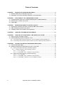
Table of Contents
CHAPTER 1
1.1
1.2
Reason and benefit of a watchdog in general .......................................................................................8
Advantage of a window watchdog compared to a usual watchdog ....................................................8
CHAPTER 2
2.1
2.2
2.3
FUNCTIONALITY OF A WINDOW WATCHDOG..........................................................9
Fundamental description of the window watchdog timer in 78K0/Fx2/Kx2/Lx2.................................9
Window open / window close period ...................................................................................................10
Option Byte.............................................................................................................................................11
CHAPTER 3
3.1
3.2
3.3
REASON FOR A WINDOW WATCHDOG.....................................................................8
WINDOW WATCHDOG IN THE APPLICATION .........................................................13
Supervision of window close time to find proper WDT restart condition .........................................13
WDT restart during window open period .............................................................................................14
Handling of timer H1 for window close supervision...........................................................................14
CHAPTER 4
HANDLING THE WINDOW OPEN PERIOD................................................................15
CHAPTER 5
HANDLING OF THE INTERNAL LOW-SPEED OSCILLATOR..................................16
5.1
5.2
Stop of internal low-speed oscillator ...................................................................................................16
Window Watchdog in HALT and STOP – mode...................................................................................17
5.2.1 Functionality when internal low-speed osc. can be stopped by software (LSROSC=0) ...................17
5.2.2 Functionality when internal low-speed oscillator can not be stopped by SW (LSROSC=1) .............17
CHAPTER 6
6.1
6.2
6
OPTION BYTE SETTING FOR WINDOW WATCHDOG.............................................18
Format of the Option Byte.....................................................................................................................18
Example: Setting of the Option Byte in the user´s source file...........................................................19
6.2.1 Setting of the Option Byte using relocatable segments....................................................................19
6.2.1.1 Example: Selection of the watchdog´s behavior ......................................................................19
6.2.1.1.1 in C – language ...............................................................................................................19
6.2.1.1.2 in assembler ( IAR – workbench, used in Europe ) .........................................................19
6.2.2 Setting of the Option Byte using absolute addressing......................................................................20
6.2.2.1.1 in C – language ...............................................................................................................20
6.2.2.1.2 in assembler ( IAR – workbench, used in Europe ) .........................................................20
6.2.2.1.3 in assembler ( Japanese Tool, not available in Europe ).................................................20
Application Note U18758EE1V1AN00
List of Figures
Figure 2-2. Window close period / window open period.........................................................................10
Figure 2-3. Option byte for watchdog timer settings ..............................................................................11
Figure 2-4. Timing selection of the window watchdog ...........................................................................12
Figure 3-1. Timer H1 supervise the window close time .........................................................................13
Figure 3-2. WDT restart during open window time range ......................................................................14
Figure 3-3. Sequential restart of the WDT using timer H1 .....................................................................14
Figure 4-1. Simplified operating system, handling watchdog timer restart ............................................15
Figure 5-1. Format of internal oscillation mode register ( RCM ) ...........................................................16
Figure 6-1. Format of option byte ...........................................................................................................18
Application Note U18758EE1V1AN00
7
CHAPTER 1 REASON FOR A WINDOW WATCHDOG
1.1 Reason and benefit of a watchdog in general
In an application, after reset, the microcontroller has to control the functionality of a device. Usually the
system works properly up to the time, the device is switched off.
In rare cases, it might happen that the microcontroller is running out of control. Several reasons can be
responsible for that phenomena and the effect of being out of control to the application can show a lot
of different behaviors.
One example for malfunction might be a software bug, which guides the software into an endless loop.
In thiscase, the microcontroller shows no reaction or action at all for ever. So, the application is out of
order. The user has to initiate a reset ( e.g. by switching off and on the power ) to reactivate the
application.
A watchdog is an internal or external peripheral, which has to be restarted by the software sequential
within a pre-defined timing range. If the software runs fail ( e.g. by stucking in an endless loop ) and
the watchdog is not restarted within the expected time, the watchdog generates an hardware reset.
Using such kind of security - peripheral, it is given that an application does not stuck for all time and
the application restarts and recovers. This does not prohibit the malfunction, but it recovers the
application.
1.2 Advantage of a window watchdog compared to a usual watchdog
A usual watchdog has only one ( selectable ) time period within the watchdog can be restarted. The
restart can be anywhere up to the time where the watchdog time has elapsed. There is only one
restriction for proper functionality of the application: restart has to be done before watchdog - timer
overflows.
If the microcontroller stucks in an endless loop in which restarting of the watchdog – timer is
implemented accidently, the microcontroller will also stuck for ever, as if no watchdog is implemented
at all.
The window watchdog timer ( WDT ) has two time stamps within the restart is allowed: A dedicated
time after WDT start and the overflow time, the so called “open window”. When a restart is triggered
during this time frame, WDT restart is done. If the restart is triggered outside this window, a reset of
the microcontroller is initiated.
The chance that the microcontroller will stuck just within an endless loop where a restart of the
watchdog – timer is implemented by accident might be very seldom. Stucking in an endless loop
where a restart of the watchdog – timer is implemented just within the watchdog window open time
frame might be nearly impossible.
So, the window watchdog increase the security level of the system, compared to a simple watchdog.
An internal window watchdog is implemented in 78K0/Fx2/Kx2/Lx2 subseries.
8
Application Note U18758EE1V1AN00
CHAPTER 2 FUNCTIONALITY OF A WINDOW WATCHDOG
2.1 Fundamental description of the window watchdog timer in 78K0/Fx2/Kx2/Lx2
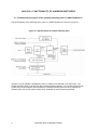
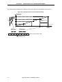
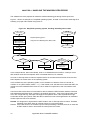
The block diagram of the watchdog timer ( WDT ) in 78K0/Fx2/Kx2/Lx2 is shown in Figure 2-1.
Figure 2-1. Block diagram of window watchdog timer
Operation can be enabled or disabled by means of setting of bit WDTON in the option byte. The
window watchdog timer is clocked with the internal low-speed oscillator. The overflow time and open
window time can be selected. When enabled, the window watchdog timer has to be restarted by
software within the choosen open window time; otherwise an internal reset is generated.
9
Application Note U18758EE1V1AN00
CHAPTER 2
FUNCTIONALITY OF A WINDOW WATCHDOG
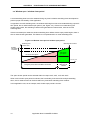
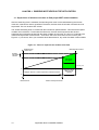
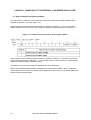
2.2 Window open / window close period
A usual watchdog timer has to be restarted during any time but before watchdog timer has elapsed to
perform proper functionality of the application.
In opposite to a usual watchdog timer, the window watchdog timer has to be restarted during a specific
time period, the so called window open period ( see: Figure 2-2 ). If there is no restart during the
window open period, the watchdog overflows and generates an internal reset, same as a usual
watchdog timer.
If there is an attempt to restart the window watchdog timer before window open period begins, there is
also an internal reset generated. This feature is not implemented in an usual watchdog timer.
Figure 2-2. Window close period / window open period
Watchdog timer
counter value
Watchdog timer overflow
Example:
25% window
is selected
75% window close period
25% window
open period
t (watchdog timer)
0
During this period, restart of the WDT is not allowed
During this period,
WDT has to be
restarted
The open window period can be selected within four steps: 25%, 50%, 75% and 100%.
When 100% window open period is selected, the functionality is the same like a simple watchdog
timer, due to restart access can be done within any time below watchdog timer overflow.
In this application note, as an example, 25% window open period is chosen.
10
Application Note U18758EE1V1AN00
CHAPTER 2
FUNCTIONALITY OF A WINDOW WATCHDOG
2.3 Option Byte
In case of 78K0/Fx2/Kx2/Lx2, the fundamental setting of the watchdog timer ( WDT ) is done within the
option byte. The option byte selects if the watchdog timer is enabled or not. When it is enabled, the
watch timer overflow time is valid, set with bits WDCS2 – WDCS0. Furthermore, the open window
time-frame can be fixed in four levels.
Figure 2-3. Option byte for watchdog timer settings
7
0
6
Window 1
5
4
Window 0
3
WDT ON
2
WDCS 2
WDCS 1
1
WDCS 0
0
Option - Byte
address: 0080H / 1080H
LSR OSC
Internal low-speed oscillator ( 240 kHz )
0 = can be stopped by software
1 = can not be stopped by software
Watchdog timer overflow time selection
Watchdog timer on / off
0 = disabled ( no watchdog operation )
1 = enabled
Window open period selection
Due to the option byte is located within the flash area, its setting can not be changed by software. This
is an additional security item.
Remarks:
Window open period ( Window1, Window0 ):
Take care that the window open period is wide enough for usual handling and WDT retrigger even
when CPU is under highest load and interrupt handling is necessary. If necessary, select a wider
window period.
Watchdogtimer enable / disable ( WDTON ):
When WDT is enabled, be aware that the watchdog timer starts operation just after reset release. For
proper functionality of the application, you have to take care to restart the WDT periodical or stop the
internal low-speed oscillator ( if LSROSC = 0 ).
Internal low-speed oscillator can be switched off / cannot be switched off by software ( LSROSC ):
If you choose “cannot be switched off by software”, be aware that you have to take care to restart the
WDT periodical in any case, even in HALT and in STOP mode.
Application Note U18758EE1V1AN00
11
CHAPTER 2
FUNCTIONALITY OF A WINDOW WATCHDOG
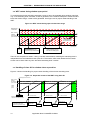
The correspondence between bit – setting in option byte and timing is described in the Figure 2-4.
Figure 2-4. Timing selection of the window watchdog
Watchdog timer
counter value
25 %
50 %
75 %
25% window open
period
100 %
t (watchdog timer)
0
watchdog timer
overflow
Window open
period selection
7
6
0
Window 1
5
Window 0
Watchdog timer
overflow selection
4
3
2
1
0
WDTON
WDCS2
WDCS1
WDCS0
LSROSC
Option - Byte addr. 0080H / 1080H
Watchdog timer on / off
12
Application Note U18758EE1V1AN00
CHAPTER 3 WINDOW WATCHDOG IN THE APPLICATION
3.1 Supervision of window close time to find proper WDT restart condition
After the watchdog timer is restarted, the watchdog timer must not be resetted during the window
close time, otherwise a reset is generated. Therefore, the time when the window is closed has to be
supervised. This can be done with a timer.
The window watchdog timer is clocked with the internal low-speed oscillator. This internal low-speed
oscillator has a tolerance. To eliminate this tolerance, the timer which supervises the window
watchdog timer should be clocked with the same oscillator in best case. So, timer H1 is optimal to be
used for the supervision of the window – close time, due to the same clock source is used ( see:
Figure 2-2 ). Of course, when you are aware about that tolerance, any other time base is also suitable.
Figure 3-1. Timer H1 supervise the window close time
Watchdog timer
counter value
Watchdog timer overflow
Example:
25% window
selected
25% window
open period
t (watchdog timer)
0
Example: Timer H1 is used for supervision of window close time
0
Restart timer H1
13
Overflow / Interrupt of timer H1
Application Note U18758EE1V0AN00
During this period,
WDT has to be
restarted
CHAPTER 3
WINDOW WATCHDOG IN THE APPLICATION
3.2 WDT restart during window open period
To avoid that the window watchdog generates a reset, it has to be restarted during window open time
only. If the watchdog timer overflows, a reset is generated. If the software attempts to restart the WDT
below the window range, a reset is also generated. See Figure 3-2 for proper restart handling of the
WDT.
Figure 3-2. WDT restart during open window time range
Watchdog timer
counter value
WDT - overflow ( in this timing range ) will generate a reset
WDT - overflow
25% window open period
Example:
25% window
open selected
Setting WDTE = 0xAC
( in this timing range )
will generate a reset
0
t (watchdog timer)
First setting of WDTE = 0xAC
after reset release
will restart the watchdog timer
independant of open window setting
Reset
release
Setting WDTE = 0xAC
( within window open period )
will restart the watchdog timer
There is one exception for restart – timing. Just after reset release, restarting the watchdog timer is
independent from the selected window open time. That means, after reset release the first restart
access can be done within any time but before watchdog timer overflow.
3.3 Handling of timer H1 for window close supervision
Figure 3-3 shows the handling for proper restart handling of the window watchdog timer.
Figure 3-3. Sequential restart of the WDT using timer H1
Watchdog timer counter value
WDT - overflow
Example:
25% window
open selected
25% window open period
window
closed
period
0
t (watchdog timer)
Reset release
0
0
Timer H1 run time
0
Timer H1 run time
Timer H1 run time
Example: Timer H1 is used for
supervision of window close time
First setting of WDTE = 0xAC
AFTER RESET RELEASE
will restart the watchdog timer
independent of open window setting
14
WDTE = 0xAC and
Timer H1 start
WDTE = 0xAC and
Timer H1 restart
WDTE = 0xAC and
Timer H1 restart
Prepare
WDT reset
Prepare
WDT reset
Application Note U18758EE1V1AN00
Prepare
WDT reset
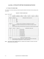
CHAPTER 4 HANDLING THE WINDOW OPEN PERIOD
The software has to be prepared to restart the window watchdog just during window open time.
Figure 4-1 shows an example of a simplified operating system, focused on the window watchdog timer
handling, for proper WDT restart using timer H1.
Figure 4-1. Simplified operating system, handling watchdog timer restart
Interrupt:
Timer H1 overflow
Reset release
Stop Timer H1 operation
Basic initialisation
Simplified operating system :
Using timer H1 for Watchdog timer ( WDT ) restart
Initialise timer H1
< WDT overflow time
> WDT window open start
WDT Restart marker = 1
RETI
Restart WDT timer :
WDTE = 0xAC
Start timer H1
Execute Task 1
?
yes
Task 1
no
Execute Task x
?
no
WDT
Restart marker = 1
?
yes
Task x
no
yes
WDTE = 0xAC
WDT Restart marker = 0
Start timer H1
In the example above, after reset release, timer H1 is initialized that its overflow – interrupt occurs
after window close time has elapsed. WDT is restarted and timer H1 is started.
An timer H1 interrupt service routine is implemented to set a marker bit that window close time has
been elapsed, for further action in the operating system.
In the endless loop of the operating system, one of its tasks is to detect if timer H1 has had an
overflow or not ( WDT restart marker = 1 ? ). If the marker is set, the task has to restart the WDT, the
marker has to be resetted and the timer H1 has to restart for supervision of the next window close
period.
User has to take care that the microcontroller is able to restart the WDT between window close time
has elapsed and watchdog timer overflows ( the window open time ), even at the highest load of the
CPU. Don´t forget that e.g. interrupts can lengthen the operation time. If the expected time might
exceed the window open period, either the WDT overflow time has to be lengthened or an extended
window open time has to be selected.
Remark: It is dangerous to implement the WDT restart in the H1 interrupt service routine. Therefore
restarting of the WDT within an interrupt routine is not recommended.
Reason: If the CPU stucks in an endless loop but interrupt handling is enabled, there is no reset due
to WDT restart is done in time within the interrupt service routine.
15
Application Note U18758EE1V0AN00
CHAPTER 5 HANDLING OF THE INTERNAL LOW-SPEED OSCILLATOR
5.1 Stop of internal low-speed oscillator
The value of bit 0 ( LSROSC ) in the option byte selects if the internal low-speed oscillator can be
stopped by software or not ( see: Figure 2-3 ).
When stopping of the internal low-speed oscillator is enabled ( LSROSC = 0 ), Bit 1 of the RCM –
register (LSRSTOP) can be used to run or stop the internal low-speed oscillator ( see: Figure 5-1 ).
Figure 5-1. Format of internal oscillation mode register ( RCM )
When stopping of the internal low-speed oscillator is enabled ( LSROSC = 0 ) and Bit 1 of the RCM –
register is set by software ( LSRSTOP = 1 ), the watchdog timer ( and the timer H1 if clocked with the
internal low-speed oscillator ) will halt counting.
This feature can be used for halting the watchdog timer for a certain time.
When the internal low-speed oscillator is stopped, the counter values in WDT ( and H1 ) keep their
values and there is no reset of its counter values. Keep that in mind, when you will enable internal lowspeed oscillator operation again.
16
Application Note U18758EE1V0AN00
CHAPTER 5
HANDLING OF THE INTERNAL LOW-SPEED OSCILLATOR
5.2
Window Watchdog in HALT and STOP – mode
5.2.1
Functionality when internal low-speed osc. can be stopped by software (LSROSC=0)
When stopping of the internal low-speed oscillator is enabled ( LSROSC = 0 ), the internal low-speed
oscillator is halted automatically, when the HALT or STOP instruction is executed. So, also the
watchdog timer stops its operation during HALT and STOP – mode, when enabled ( WDTON = 1 ).
In this case it is not necessary to set LSRSTOP = 1 by software before entering HALT or STOP to
economize power consumption.
After HALT or STOP release, internal low-speed oscillator starts operation again.
During HALT and STOP, the counter values in WDT ( and H1, when clocked with internal low-speed
oscillator ) keep their values; there is no reset of its counter values.
5.2.2
Functionality when internal low-speed oscillator can not be stopped by SW (LSROSC=1)
When the watchdog timer is enabled ( WDTON = 1 ) and stopping of the internal low-speed oscillator
is not possible ( LSROSC = 1 ), the internal low-speed oscillator, the watchdog ( and the timer H1,
when clocked with internal low-speed osc. ) keeps operation, even when the HALT or STOP
instruction is executed.
In this case, user has to take care that the CPU has to be waked up cyclic to restart the watchdog
timer.
This will increase the power consumption, especially during STOP – mode.
For cyclic restart of the watchdog timer, a timer has to be used, which is able to operate during
standby. E.g. timer H1 operating with internal low-speed oscillator, watch timer using 32 kHz sub clock
or a timer clocked externally.
Application Note U18758EE1V1AN00
17
CHAPTER 6 OPTION BYTE SETTING FOR WINDOW WATCHDOG
6.1 Format of the Option Byte
The selection for window watchdog / internal low-speed oscillator functionality is done by setting of the
option byte.
Figure 6-1. Format of option byte
Note
18
Set the same value at address 0080H and 1080H because 0080H and 1080H are switched
during the boot swap operation.
Application Note U18758EE1V0AN00
CHAPTER 6
OPTION BYTE SETTING FOR WINDOW WATCHDOG
6.2 Example: Setting of the Option Byte in the user´s source file
The option byte(s) has (have) a specific location within the microcontrollers address range. The
address of the option byte is specified in the microcontrollers “.xcl – file”, delivered by NEC.
6.2.1
Setting of the Option Byte using relocatable segments
As an example, the following segment definition is included in a specific xcl – file for the WDT - Option
Byte:
//---------------------------------------------------------------------// Allocate OPTION BYTE segment
//----------------------------------------------------------------------Z(CODE)OPTBYTE=0080-0081
6.2.1.1 Example: Selection of the watchdog´s behavior
6.2.1.1.1 in C – language
# pragma location = “OPTBYTE”
// Definition of the segment for the option byte ( .xcl – file )
__root const unsigned char myoptionbyte[ 2 ] = {0x10, 0x00};
// Watchdog timer operation enabled
// Window open period of watchdog timer: 25%,
// Overflow time of watchdog timer: 210/fRL
// Low-speed oscillator can be stopped by software
// Second value just to fillup the odd address
6.2.1.1.2 in assembler ( IAR – workbench, used in Europe )
RSEG OPTBYTE
DB
00010000B
DB
00000000B
; Reference to .xcl – file, address 0x0080
; Watchdog timer operation enabled
; Window open period of watchdog timer: 25%,
; Overflow time of watchdog timer: 210/fRL,
; Internal low-speed oscillator can be stopped by software
; Second value just to fillup the odd address
Application Note U18758EE1V1AN00
19
CHAPTER 6
6.2.2
OPTION BYTE SETTING FOR WINDOW WATCHDOG
Setting of the Option Byte using absolute addressing
6.2.2.1.1 in C – language
__root const unsigned char myoptionbyte @ 0x0080 = 0x39;
// Absolute addressing at address 0x0080
// Watchdog timer operation enabled
// Window open period: 50%
// Overflow time of watchdog timer: 214/fRL
// Low-speed oscillator cannot be stopped by SW
6.2.2.1.2 in assembler ( IAR – workbench, used in Europe )
ASEG
ORG 0x0080
DB
00111001B
; Absolute addressing at address 0x0080
; Watchdog timer operation enabled
; Window open period: 50%
; Overflow time of watchdog timer: 214/fRL
; Low-speed oscillator cannot be stopped by software
6.2.2.1.3 in assembler ( Japanese Tool, not available in Europe )
OPT
OPTION:
20
CSEG AT
DB
0080H ; Set absolute addressing at 0080 hex.
39H
; Enables watchdog timer operation
; Window open period: 50%
; Overflow time of watchdog timer: 214/fRL
; Low-speed oscillator cannot be stopped by software
Application Note U18758EE1V1AN00