1
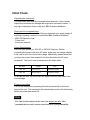
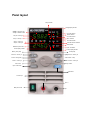
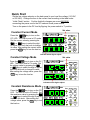
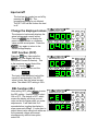
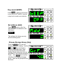
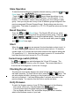
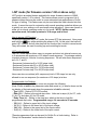
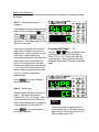
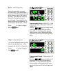
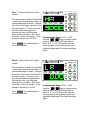
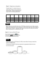
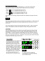
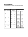
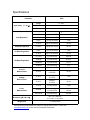
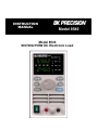
INSTRUCTION MANUAL Model 8540 Model 8540 60V/30A/150W DC Electronic Load WARNING Safety Regulations To avoid electrical shock, do not open the cabinet. Refer servicing to qualified personnel only. To avoid injuries, always disconnect power, discharge circuits, and remove external voltage sources before touching components. KEEP AWAY FROM LIVE CIRCUITS. We cannot accept responsibility for any direct or indirect financial damage or loss of profit that might occur when using the electronic load. The instrument chassis and cover must be connected to an electrical ground. Certification We certify that this product met its published specifications at time of shipment from the factory. Notice The information contained in this document is subject to change without notice. Please consult the B&K Precision website www.bkprecision.com for the latest version. Compliance Statements Disposal of Old Electrical & Electronic Equipment (Applicable in the European Union and other European countries with separate collection systems) This product is subject to Directive 2002/96/EC of the European Parliament and the Council of the European Union on waste electrical and electronic equipment (WEEE) , and in jurisdictions adopting that Directive, is marked as being put on the market after August 13, 2005, and should not be disposed of as unsorted municipal waste. Please utilize your local WEEE collection facilities in the disposition of this product and otherwise observe all applicable requirements. Safety Symbols Connect it to safety earth ground using the wire recommended in the user’s manual. High voltage danger The symbol on an instrument indicates that the user should refer to the operating instructions located in the manual. Initial Check Unpacking the instrument This instrument was carefully inspected before shipment. Upon receipt, inspect the instrument for damage that might have occurred in transit. If any sign of damage is found, notify your B&K Precision distributor. Check the list of supplied items Verify that you have received the following items with your power supply. If anything is missing, contact your authorized B&K Precision distributor. - 8540 DC Electronic load - Power cord - Instruction manual Power Requirements The 8540 can operate on 110V AC or 220V AC line input. Before connecting the power cord to an AC outlet, make sure the voltage selector in the rear is set to the correct line voltage. Additionally, please check that you have the correct fuse inserted in the fuse box below the AC input receptacle. The fuse to use is referenced in the below table: AC Input Range Fuse 110V AC 99 V to 121 V T0 500 mA, 250V 220V AC 198 V to 242 V T0 250 mA, 250V To access the fuse, first disconnect the power cord and then remove the fuse cartridge. Power-on procedure Turn on the instrument by pressing the main power switch on the front panel of the unit. The instrument will automatically revert to the last setting before the power was turned off. Note The 9 pin D-sub connector in the rear is for factory use only! This instrument does not offer remote control interface or programmability. About the 8540 The B&K Precision 8540 DC electronic load (60V/30A/150W) can sink DC current in constant current, constant voltage, and constant resistance modes. Measured values have 10 mV and 1 mA resolution. Shorts can be simulated. Storage is provided for up to *40 groups, with 4 instrument setups per group. The instrument is easy to use and will find many uses for testing DC power supplies, batteries, and DC to DC converters. Constant Current (CC) mode VV In CC mode, the DC load draws a constant current regardless CC 時, of the voltage on its terminals. ,ITECH 為幾伏特 I I來吸取電流 Constant Current Constant current Constant Voltage (CV) mode In CV mode, the DC load will draw enough current to keep the voltage at the terminals constant. V I Features Full digital control 1mV /1mA measurement resolution Compact size Bright, readable LED display Operating modes: CC/CV/CR Input on/off control High reliability due to OCP/OVP (over current, over voltage) protection Storage for *40 groups, 4 setups each Easy operation Constant voltage Constant Resistance (CR) mode V In CR mode, the DC load will sink a current linearly proportional to the voltage at the terminals. I Constant resistance *40 groups are applicable for units with firmware version 1.60 or above. For versions below 1.60, 100 groups are available. Go to “Verify firmware” section to determine your instrument version. Panel layout Setup indicator Voltage display indicator Voltage or preset current, voltage or resistance value Step B + memory B Step A + memory A Step C + memory C Step D + memory D CC mode indicator Recall indicator CV mode indicator Short indicator CR mode indicator 30A mode selector indicator Shift indicator Current or power value Power display indicator Input off indicator Current display indicator Memory save (shift) Recall (shift) Left arrow + memory A Right arrow + memory B Function setup (shift) Switch + memory C Short on/off 3/30A selector(shift) Mode selector + memory D Rotary encoder Input on/off button Shift button Air flow input Input + Main power on/off Input - Quick Start Set the line voltage selector on the back panel to your local line voltage (110 VAC or 220 VAC). Change the fuse to the correct fuse according to the table under “Initial Check” section. Confirm that both changes are correct BEFORE connecting the power cord to the DC load and a wall power socket. Turn on the power to the DC load by flipping the power switch to “I” position. Set value Constant Current Mode Press the D Mode 8540 key to turn on the 150W DC Electronic Load CC LED. The load is now in CC mode. Set the current value by pressing the fA or B keys to select the digit to adjust, then turn the knob to change its value. After setting the current value, press the On/Off key to turn the load on. A C B Set Recall CC V Short CV W 30A CR A OFF Shift D Indicates which digit to adjust Constant Voltage Mode Press the D Mode key to turn on the CV LED. The load is now in CV mode. Set the voltage value by pressing the A or B keys to select the digit to adjust, then turn the knob to change its value. After setting the voltage value, press the On/Off key to turn the load on. Set value 8540 150W DC Electronic Load A B C D Set Recall CC V Short CV W 30A CR A OFF Shift Set Recall CC V Short CV W 30A CR A OFF Shift Indicates which digit to adjust Constant Resistance Mode Press the D Mode key to turn on the CR LED. The load is now in CR mode. Set the resistance value by pressing the A or B keys to select the digit to adjust, then turn the knob. After setting the voltage value, press the On/Off key to turn the load on. 8540 150W DC Electronic Load A B C D Input on/off The load can be toggled on and off by pressing the On/Off key. The programmed setting is not affected. The OFF LED will be lit when the load is off. Change the displayed values The electronic load usually displays the actual voltage and current values. Press the C View key to display the preset voltage, current or resistance value and the actual power. Press the fC View key again to return to the current/voltage display. 8540 150W DC Electronic Load A B C D Set Recall CC V Short CV W 30A CR A OFF Shift Set Recall CC V Short CV W 30A CR A OFF Shift Set Recall CC V Short CV W 30A CR A OFF Shift OCP function (OCP) Press the Shift key, then press the C View key. The display will show OCP (Over Current Protection). This is the maximum current that will be allowed. Use the A and B keys and the knob to set the value. 8540 150W DC Electronic Load A B C D NOTE The input of the electronic load will be turned off automatically if the OCP value is lower than the actual current value. The default OCP setting is 30 A. REL function (rEL) After setting OCP, press C View to enter the REL setting. Use the knob to select ON or OFF. The default is OFF, which means the display will show your set value on the top display while you make adjustments. It will then blink for 2 seconds before toggling the display to show measured voltage. If users want to adjust the set value using knob while see the measured voltage and current simultaneously without interruption, select ON. 8540 150W DC Electronic Load A B C D Key sound (bEEP) 8540 150W DC Electronic Load Set Recall CC V Short CV W 30A CR A OFF Shift Set Recall CC V Short CV W 30A CR A OFF Shift Set Recall CC V Short CV W 30A CR A OFF Shift C View Press again to turn the key sound ON or OFF (bEEP). Use the rotary knob to make your selection. A B C Set address (Add) Press C View twice to skip the address menu and advance to the next menu. NOTE D 8540 150W DC Electronic Load A B C D This setting is for factory use only and should be ignored. Choose Storage Group (Grp) Press the C View key to see the storage group (GrP) setting. Use the A and and B keys and knob to choose the storage group. Each group can store four instrument settings (Each setting can store two parameters). (see storage operation). Press the C View key to confirm selection of the displayed storage group. There are 40 groups that can be stored. 8540 150W DC Electronic Load A B C D Store Operation To save the load’s settings to a register (internal memory), press the Shift and A (Save) keys. The A B C D LEDs will blink together. Press the A or B or C View or D Mode keys to save the settings to non volatile memory. Pressing A will store to A location. B to B location. C to C location. D to D location. Hence, users can save up to four settings in each group. Note you may do this for any of the 40 different groups assigned in the previous paragraph (Choose Storage Group). Each settings can store two parameters: The mode of operation (i.e. CC, CV, CR) and the values set for that mode. Recall Operation Press the Shift and B (Recall) keys. The Recall LED will turn on, which means you may recall settings from the currently-chosen group. Press the A or B or C View or D Mode keys to recall the desired setting. When the Recall LED is lit, the other keys are disabled. To exit the recall state, press the Shift and B (Recall) keys again. Short When the Shift + On/Off keys are pressed, the load simulates a short circuit. In CC and CR modes, the maximum short-circuit current value is 1.2 times the current range. In CV mode, the short-circuit current is the same as setting the CV operation to 0.1 V. Note that the short-circuit current in CV mode will be less than the short-circuit current in CC or CR modes. Current range switch (3/30 A) The Shift and D Mode keys switch between the 3 A and 30 A ranges. The 30A LED is lit when the load is on the 30 A range. The current resolution is 10 mA for the 30 A range and 1 mA for the 3 A range. Checking the set value The electronic load usually displays the actual voltage and current values at the load’s terminals. To check the set value, press the A or B keys. The set value display will blink, showing you the currently-set value. You can use the knob to change it. It will stop blinking after 3 seconds and revert to the previous display. You can also turn the knob to see the set value. Verify Firmware To verify the firmware version of your DC Electronic load, do the following: - First, power off the unit. Then hold down the C View button. - Turn the power switch ON while holding down the C View button. - The top display will show “VEr” and bottom display will show a number, which is the firmware version of your load. LIST mode (for firmware version 1.60 or above only) LIST mode is an added feature applicable for newer firmware versions of 8540, specifically version 1.60 or above. This feature allows users to program a list of sequence steps that may be useful in some automated test applications or Go/No Go type of testing. This feature can only be used when the load is booted into this mode. It cannot be used in conjunction with normal operating mode that allows you to quickly set your settings or do save/recall setup operations. Users can choose to either run in normal operating mode or in list mode. NOTE: Unlike normal operation mode, list mode operates in 30 A range and is fixed. How to access LIST function To boot the instrument into LIST mode, first power OFF the instrument. Now, press and hold the B key while switching the power to ON. At this point, the load will enter LIST function, and all other keys will not function like it would in normal mode. They will instead, be used for setting up and controlling list mode. LIST mode structure The LIST mode feature allows users to program and store into internal memory up to 4 sequences with maximum of 25 steps in each sequence. The storage memory is broken down into 4 blocks for storing sequences. We will refer these sequences as A, B, C, and D. - Sequence A stores step 0 to 24 (25 steps total). - Sequence B stores step 25 to 49 (25 steps total). - Sequence C stores step 50 to 74 (25 steps total). - Sequence D stores step 75 to 99 (25 steps total). Users can store a combine (all 4 sequences) total of 100 steps, but are only allowed to run one sequence (for maximum of 25 steps) at a time. Programmable List Settings When programming each step, users can program the following: (Note: Words in bold is the parameter name and words in () is what’s shown on the top display of the instrument when the parameter in bold is selected) - Type (tyPE) - Refers CC/CV/CR modes) - Data (dAt) – Refers to the actual step value. Units are in amps (A) for CC, volts (V) for CV, and ohms (Ω) for CR mode. - Delay Time (dt) – Refers to the step time, which is the time to hold the programmed step value. Programmable range: 0.4 seconds to 25 seconds - *HV (HU) – Refers to upper limit of the input voltage. - *LV (LU) – Refers to the lower limit of the input voltage. - *HA (HA) – Refers to the upper limit of the input current. - *LA (LA) – Refers to the lower limit of the input current. *Denotes parameters that can be used for Go/No Go or limits testing. Refer to “Setup List Parameters” section below for details. Setup List Parameters Below is an example with step by step instructions on setting up a sequence using list modes. Step 1 – Select step number to program If not already, boot the instrument into LIST mode by holding the B key while switching on the power button. Press Shift , then C View to enter the LIST menu for programming LIST parameters. The display will look like the one on the right. If you want to program from the first step, leave it shown on the bottom display as 0. In this example, we will start from 0. After entering all parameters assigned for the step, the menu system will automatically go back to this setup screen with step number automatically incremented by 1. You only need to adjust this if you want to edit a programmed step later on or if you want to program a different step. Press C View to go and configure the next parameter. Step 2 – Select type Bottom display will show the type for step 0. Use the knob to select between CC, CV, or CR type. When running the list, this step will set the load to the selected type of operation. In this example, we will select CC. Press to go and configure the next parameter. C View 8540 150W DC Electronic Load A B C D Set Recall CC V Short CV W 30A CR A OFF Shift Programmable Range: 0 – 99 B Use the A keys to change cursor position shown by the LED light next to either A, B, C, or D (These four denotes cursor position, with A selecting the most significant figure and D the least significant figure. 8540 150W DC Electronic Load A B C D Set Recall CC V Short CV W 30A CR A OFF Shift NOTE Users can create a sequence with a mixed combination of different types in each step (i.e. One step can run in CC while another step in CV) Step 3 – Select step value Select the data value you want programmed for the selected step. If you enter 0.000, this denotes the end of the sequence and it will stop on this step. The maximum value will depend on the type selected in previous step. See programmable range on the right for reference. In this example, we will enter 1.000 A. Press to go and configure View the nextCparameter. 8540 150W DC Electronic Load A B C D Recall CC V Short CV W 30A CR A OFF Shift Programmable Range: 0.000 (CC) / 0.100 (CV) / 0.100 (CR) – 30.00 (CC) / 60.0 (CV) / 4000 (CR) B Use the A keys to change cursor position shown by the LED light next to either A, B, C, or D (These four denotes cursor position, with A selecting the most significant figure and D the least significant figure. Step 4 – Select delay time 8540 150W DC Electronic Load “dt” on the top display refers to delay time for the selected step. In this example, we will set it to 5 seconds. A Press to go and configure C View the next parameter. Set B C D Set Recall CC V Short CV W 30A CR A OFF Shift Programmable Range: 0.4 seconds to 25 seconds. B Use the A keys to change cursor position shown by the LED light next to either A, B, C, or D (These four denotes cursor position, with A selecting the most significant figure and D the least significant figure. Step 5 – Select upper limit of input voltage 8540 150W DC Electronic Load Set Recall CC Short CV V This parameter is used to limit testing or test setups that must stay within a A C B D CR 30A customized range of values. Change W this value to the upper bound limit for A OFF Shift the input voltage. If voltage exceeds this limit while the sequence is running this step, it will stop and show an error condition. See “Error Condition” section for details. In this Programmable Range: 0.00 – 60.00 example, we will set to 60.00 V. B Use the A keys to change cursor position shown by the LED light next to Press C View to go and configure either A, B, C, or D (These four denotes the next parameter. cursor position, with A selecting the most significant figure and D the least significant figure. Step 6 – Select lower limit of input voltage 8540 150W DC Electronic Load Set Recall CC V Short CV This parameter is used to limit testing or test setups that must stay within a C B D CR 30A customized range of values. Change A W this value to the lower bound limit for the input voltage. If voltage is less A OFF Shift than this limit while the sequence is running this step, it will stop and show an error condition. See “Error Condition” section for details. In this Programmable Range: 0.00 – 60.00 example, we will set to 0.00 V. B Use the A keys to change cursor position shown by the LED light next to Press to go and configure either A, B, C, or D (These four denotes View the nextCparameter. cursor position, with A selecting the most significant figure and D the least significant figure. Step 7 – Select upper limit of input current 8540 150W DC Electronic Load Set Recall CC Short CV Recall CC V This parameter is used to limit testing or test setups that must stay within a A C B D CR 30A customized range of values. Change W this value to the upper bound limit for A OFF Shift the input current. If current exceeds this limit while the sequence is running this step, it will stop and show an error condition. See “Error Condition” section for details. In this Programmable Range: 0.00 – 30.00 example, we will set to 30.00 A. B Use the A keys to change cursor position shown by the LED light next to Press C View to go and configure either A, B, C, or D (These four denotes the next parameter. cursor position, with A selecting the most significant figure and D the least significant figure. Step 8 – Select lower limit of input current 8540 150W DC Electronic Load Set V Short CV This parameter is used to limit testing or test setups that must stay within a C B D CR 30A customized range of values. Change A W this value to the lower bound limit for the input current. If current is less A OFF Shift than this limit while the sequence is running this step, it will stop and show an error condition. See “Error Condition” section for details. In this Programmable Range: 0.00 – 30.00 example, we will set to 0.00 A. B Use the A keys to change cursor position shown by the LED light next to Press C View to go and configure either A, B, C, or D (These four denotes the next parameter. cursor position, with A selecting the most significant figure and D the least significant figure. Step 9 – Repeat step configurations Repeat steps 1-8, except in step one, select step number as an increment to the next step. Create a sequence of 5 steps with the following parameters: Steps Type 1 2 3 4 CV CR CC CC Data Value Delay Time 2.000 V 10.00 Ω 2.000 A 0.000 A 5s 5s 5s 5s Upper Voltage Limit Lower Voltage Limit Upper Current Limit Lower Current Limit 60.00 V 60.00 V 60.00 V 60.00 V 0.00 V 0.00 V 0.00 V 0.00 V 30.00 A 30.00 A 30.00 A 30.00 A 0.00 A 0.00 A 0.00 A 0.00 A NOTE Steps 4 has been set with data value of 0.000 A to denote the end of the sequence. Always set the last step of your sequence to 0.000 under data value if the sequence has less than 25 steps. Otherwise, the load will only stop at the step that contains either a data value of 0 or after the 25th step. Step 10 – Save and Exit LIST menu. Once finished, press the Shift key, then press C View key to save and exit the programmed sequence(s). NOTE Users can program all 100 steps (0 to 99) at once without having to select the memory storage group. Following the example, the below sequence is programmed and can be ran from the instrument. 10 Ω, CR 2 V, CV 2 A, CC 1 A, CC 5 seconds 5 seconds 5 seconds 5 seconds Run Programmed Sequence After programming and saving the sequence(s), you can start running those sequences by doing the following (Only 25 steps can be run at one time): - Press - Press - Press - Press A B C D key to run programmed steps 0 to 24. key to run programmed steps 25 to 49. View key to run programmed steps 50 to 74. Mode key to run programmed steps 75 to 99. When sequence is running, a beep sound will occur whenever it jumps to the next step. NOTE Although programmed steps can be set with minimum resolution of 1 mA/1 mV/1 mΩ, when running the sequence the minimum display resolution will only be 10 mA/10 mV/10 mΩ. The running sequence will stop if the step data value is 0.000. It will not run all 25 steps in each sequence unless each step has a data value greater than 0.000. CAUTION: Once a sequence starts running, other key press will interrupt the setting, but the sequence will still continue to run until it ends. Additionally, the input will turn ON automatically. To stop the sequence immediately, go into the LIST menu and exit again. This will stop the sequence, but input status will remain ON if it was already ON prior to entering the LIST menu. Otherwise, turning the power switch OFF will be the quickest and safest way to end the run. Error Condition The upper and lower limit voltage and current parameters in each step configuration sets test boundaries. While a sequence is running, if the measured voltage or current exceeds these boundaries, an error condition will occur to indicate a “fail” to the test sequence. The top display will show “SP #” where # is the step number that triggered the error. At this point, you will hear rapid beeping for 5 seconds before the sequence ends. 8540 150W DC Electronic Load A B C D Set Recall CC V Short CV W 30A CR A OFF Shift NOTE For safety, the input terminal will automatically be turned OFF after the error condition occurs. Knob incremental values The following table shows the incremental changes in the set value when the knob is turned corresponding to which “cursor” LED is lit. Cursor position A B C D Voltage Increment 10 V Current Increment Range Increment 0-3 A 1A 0-30 A 10 A 0-3 A 0.1 A 0-30 A 1A 0-3 A 0.01 A 0-30 A 0.1 A 0-3 A 0.001 A 0-30 A 0.01 A 1V 0.1 V 0.01 V Resistance Increment Range Increment 0.1-10 Ω 1Ω 10-99 Ω 10 Ω 100-999 Ω 100 Ω 1000-4000 Ω 1000 Ω 0.1-10 Ω 0.1 Ω 10-99 Ω 1Ω 100-999 Ω 10 Ω 1000-4000 Ω 100 Ω 0.1-10 Ω 0.01 Ω 10-99 Ω 0.1 Ω 100-999 Ω 1Ω 1000-4000 Ω 10 Ω 0.1-10 Ω 0.001 Ω 10-99 Ω 0.01 Ω 100-999 Ω 0.1 Ω 1000-4000 Ω 1Ω Specifications Parameter Input rating ( 0 - 40 Ԩ) Load Regulation CV Mode Regulation CC Mode Regulation CR Mode Regulation Current Measurement Voltage Measurement Power Measurement 8540 Voltage 0 – 60 V Current 1 mA – 30 A Power 150 W Range Accuracy Resolution 0-10 V ±(0.05%+0.1%FS) 1 mV 0-60 V ±(0.05%+0.1%FS) 10 mV 0-3 A ±(0.1%+0.1%FS) 1 mA 0-30 A ±(0.1%+0.15%FS) 10 mA 0.1-60 V ±(0.05%+0.1%FS) 10 mV 0-3 A ±(0.1%+0.1%FS) 1 mA 0-30 A ±(0.1%+0.15%FS) 10 mA 0.1-10 Ω ±(1%+0.8%FS) 0.001 Ω 10-99 Ω ±(1%+0.8%FS) 0.01 Ω 100-999 Ω ±(1%+0.8%FS) 0.1 Ω 1K-4K Ω ±(1%+0.8%FS) 1Ω 0-3 A ±(0.1% + 0.1%FS) 1 mA 0-30 A ±(0.1% + 0.15%FS) 10 mA 0-10 V ±(0.05% + 0.1%FS) 1 mV 0-60 V ±(0.05% + 0.1%FS) 10 mV 0-10 W ±(1%+0.5%FS) 1 mW ±(1%+0.5%FS) 10 mW ±(1%+0.5%FS) 100 mW 10-99 W 100-150 W Dimension(W x H x D) 88 x 175 x 282 mm 3.5 x 6.9 x 11.10 inches Weight (net) 2.7 kg 6 pounds Specifications and information are subject to change without notice. Please visit www.bkprecision.com for the most current product information. Warranty Service Information Warranty Service: Please go the service and support section on our website www.bkprecision.com to obtain a RMA #. Return the product in the original packaging with proof of purchase to the address below. Clearly state on the RMA the performance problem and return any leads, probes, connectors and accessories that you are using with the device. Non-Warranty Service: Please go the service and support section on our website www.bkprecision.com to obtain a RMA #. Return the product in the original packaging to the address below. Clearly state on the RMA the performance problem and return any leads, probes, connectors and accessories that you are using with the device. Customers not on an open account must include payment in the form of a money order or credit card. For the most current repair charges please refer to the service and support section on our website. Return all merchandise to B&K Precision Corp. with pre-paid shipping. The flat-rate repair charge for NonWarranty Service does not include return shipping. Return shipping to locations in North America is included for Warranty Service. For overnight shipments and non-North American shipping fees please contact B&K Precision Corp. B&K Precision Corp. 22820 Savi Ranch Parkway Yorba Linda, CA 92887 www.bkprecision.com 714-921-9095 Include with the returned instrument your complete return shipping address, contact name, phone number and description of problem Limited One-Year Warranty B&K Precision Corp. warrants to the original purchaser that its products, and the component parts thereof, will be free from defects in workmanship and materials for a period of one year from date of purchase. B&K Precision Corp. will, without charge, repair or replace, at its option, the defective product or its component parts. The returned product must be accompanied by proof of the purchase date in the form of a sales receipt. To obtain warranty coverage in the U.S.A., this product must be registered by completing a warranty registration form on www.bkprecision.com within fifteen (15) days of purchase. Exclusions: This warranty does not apply in the event of misuse or abuse of the product or as a result of unauthorized alterations or repairs. The warranty is void if the serial number is altered, defaced or removed. B&K Precision Corp. shall not be liable for any consequential damages, including without limitation damages resulting from loss of use. Some states do not allow limitations of incidental or consequential damages. So the above limitation or exclusion may not apply to you. This warranty gives you specific rights and you may have other rights, which vary from state-to-state. B&K Precision Corp. 22820 Savi Ranch Parkway Yorba Linda, CA 92887 www.bkprecision.com 714-921-9095 Intentionally left blank 22820 Savi Ranch Parkway Yorba Linda, CA 92887 www.bkprecision.com © 2008 B&K Precision Corp. Printed in China v040814