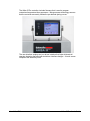
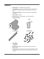
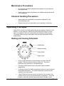
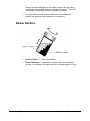
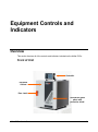
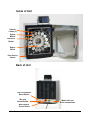
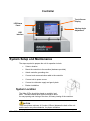
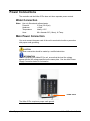
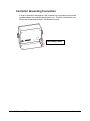
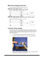
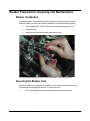
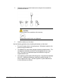
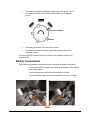
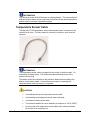
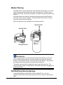
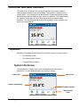
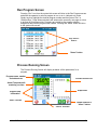
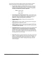
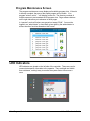
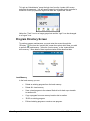
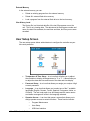
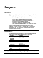
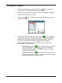
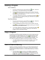
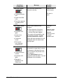
1
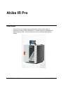
Ahiba IR Pro User’s Guide
(Part No. 72-990132, June, 2010)
All efforts have been made to ensure the accuracy of the information presented in this format.
However, should any errors be detected, Datacolor appreciates your efforts to notify us of these
oversights.
Changes are periodically made to this information and are incorporated into forthcoming versions.
Datacolor reserves the right to make improvements and/or changes in the product(s) and/or
program(s) described in this material at any time.
©2010 Datacolor. Datacolor, and other Datacolor product trademarks are the property of Datacolor.
Microsoft and Windows are either registered trademarks of Microsoft Corporation in the United
States and/or other countries.
To obtain information on local agents, contact either of the offices listed below, or visit our website
at www.datacolor.com.
Support Questions?
If you need help with a Datacolor product, please contact one of our top-rated technical support
teams located around the world for your convenience. You can find contact information below for
the Datacolor office in your area.
Americas
+1.609.895.7465
+1.800.982.6496 (toll-free)
+1.609.895.7404 (fax)
[email protected]
Europe
+41.44.835.3740
+41.44.835.3749 (fax)
[email protected]
Asia Pacific
+852.2420.8606
+852.2420.8320 (fax)
[email protected]
Or contact your local representative.
Datacolor has representatives in over 60 countries … for a complete list, visit:
www.datacolor.com/locations.
Designed and Developed by:
Datacolor USA
5 Princess Road
Lawrenceville, NJ 08648
+1.609.924.2189
Assembled at Datacolor Technology (Suzhou):
No. 288 Suhong Road,
Suzhou Industrial Park
Export Processing Zone B, Suzhou,
Jiangsu, P.R. China 215021
Committed to Excellence. Dedicated to Quality.
Certified to ISO 9001:2008 in Manufacturing Centers Worldwide.
Contents
Ahiba IR Pro .............................................................................................1
Overview ........................................................................................................ 1
Features ........................................................................................................ 3
Accessories ................................................................................................... 4
Standard Accessories............................................................................. 4
Optional Accessories .............................................................................. 4
About the Beakers ......................................................................................... 4
Safety Labels and Precautions ...................................................................... 5
General Precautions ............................................................................... 6
Electrical/Environmental Precautions ..................................................... 6
Use Precautions ..................................................................................... 6
Maintenance Precautions ....................................................................... 7
Chemical Handling Precautions ............................................................. 7
Operating Principles ...................................................................................... 7
Heating and Cooling Schematic ............................................................. 7
Beaker Rotation ...................................................................................... 8
Equipment Controls and Indicators .......................................................9
Overview ........................................................................................................ 9
Front of Unit ............................................................................................ 9
Inside of Unit......................................................................................... 10
Back of Unit .......................................................................................... 10
Controller .............................................................................................. 11
System Setup and Maintenance .................................................................. 11
System Location ................................................................................... 11
Power Connections...................................................................................... 12
Water Connection ................................................................................. 12
Main Power Connection ....................................................................... 12
Controller Grounding Connection ......................................................... 13
Controller Power Supply ....................................................................... 14
Beaker Preparation, Cleaning and Maintenance ......................................... 15
Beaker Installation ................................................................................ 15
Beaker Dosing ...................................................................................... 19
Beaker Preparation Basket................................................................... 20
Beaker Cleaning and Maintenance ...................................................... 20
Touch Screen Display Care.................................................................. 20
Program Controls ..................................................................................21
Overview ...................................................................................................... 21
Controller and User Interface....................................................................... 22
“Operator” .................................................................................................... 22
System Idle Screen .............................................................................. 22
Run Program Screen ............................................................................ 23
Ahiba IR Pro User's Guide
Contents • i
Process Running Screen ...................................................................... 23
Delayed Program Run Screen .............................................................. 25
Run “Manual Mode” Screen .................................................................. 25
Program Maintenance Screen .............................................................. 26
LED Indicators ............................................................................................. 26
Numeric Keypad .......................................................................................... 27
USB Host Interface ...................................................................................... 27
“Administrator” ............................................................................................. 27
Program Directory Screen .................................................................... 28
User Setup Screen ............................................................................... 29
Programs ................................................................................................31
Overview ...................................................................................................... 31
Limit Values ................................................................................................. 31
Creating a Program ..................................................................................... 32
Editing a Program ........................................................................................ 33
Deleting a Program ...................................................................................... 34
Copy a Program........................................................................................... 34
Save to External Memory............................................................................. 34
Load from External Memory......................................................................... 35
Running a Program...................................................................................... 35
Program Hold............................................................................................... 36
Hold Precautions and Tips ................................................................... 36
Manual Program Hold ........................................................................... 36
Alarms and Status Messages ...................................................................... 37
Audible Alerts ....................................................................................... 37
Troubleshooting Alerts and Alarms ...................................................... 38
Appendix.................................................................................................41
Specifications .............................................................................................. 41
Minimum/Maximum Beaker Loads............................................................... 42
Minimum Beaker Load .......................................................................... 42
Maximum Beaker Load ......................................................................... 42
Maintenance List.......................................................................................... 43
Glossary of Icons ......................................................................................... 44
Accessories ................................................................................................. 48
Beaker Preparation Basket................................................................... 48
Beaker Prep Basket.............................................................................. 48
Dosing Accessories .............................................................................. 49
ii • Contents
Ahiba IR Pro User's Guide
Ahiba IR Pro
Overview
Ahiba IR Pro is an infrared dyeing machine that handles a wide variety of
processes in exhaust dyeing laboratories. It can be used as an atmospheric or
high-temperature dyer. The unit can also be used to simulate wash fastness
testing.
Ahiba IR Pro User's Guide
Ahiba IR Pro • 1
The Ahiba IR Pro controller includes firmware that is used to program
customized temperature/time sequences. Microprocessor technology ensures
that the controller accurately follows the pre-defined dyeing curves.
The user interface employs an icon-driven interface that helps eliminate all
operator obstacles that exist with text-driven interface designs. A touch screen
completes the data entry tools.
2 • Ahiba IR Pro
Ahiba IR Pro User's Guide
Features
•
Heating Source: 3 1000W infrared quartz lamps.
•
Cooling Source: Cold water heat exchanger system is used to control
the chamber temperature and act to cool the beakers at controlled
rates.
•
Temperature Monitoring: Protects the equipment and samples from
overheating.
•
Type of Fibers: All fibers
•
Dyeing Positions: Accommodates up to 20 dyeing positions
•
Types of Substrates:
Piece
Hank
Combed Slivers
Loose Material
•
Liquor Ratio:
1:3 (Synthetics)
1:5 (Natural)
•
Wash Fastness Testing. Unit can also be used to simulate wash
fastness testing.
•
User Interface: Icon and menu-driven user interface. Maximum number
of custom programs stored locally is 99, each containing a maximum of
15 steps.
Ahiba IR Pro User's Guide
Ahiba IR Pro • 3
Accessories
Standard Accessories
The following accessories are included with the system:
•
Hex screwdriver for tightening and loosening beaker tops
•
Reference beaker
•
Complete set of beakers. Note: If optional dosing beakers are ordered,
all necessary accessories to complete the dosing process will be
included.
•
Replacement set of o-rings for beaker lids
•
Beaker preparation basket
•
Spare bayonet sensor
•
USB Flash Drive (Containing: User Manual, Wiring Diagram,
Application Program)
Optional Accessories
Optional accessories for the Ahiba IR Pro include the following:
•
Self-refilling dosing syringe
•
Accessories for membrane dosing
•
Accessories for injection dosing
These accessories can be ordered with the system, or ordered at a later time.
See also Appendix, Accessories List for details to order these accessories.
About the Beakers
The Ahiba IR Pro can work with several different beaker sizes. A standard unit
includes a single set of beakers, and the beaker size is defined when the order
is placed. The table below summarizes this information:
Beaker Size
(Maximum)
Maximum Number of beakers
that can fit into the unit
150 ml
20
5 grams
300 ml
15
10 grams
500 ml
8
25 grams
4 • Ahiba IR Pro
Ideal Sample
Size
500 ml
10
25 grams
1000 ml
8
50 grams
5 liter
1
250 grams
Ahiba IR Pro User's Guide
INFORMATION
A unit can be equipped with either dosing or non-dosing beakers. Injection dosing
or membrane dosing beakers are available.
Units equipped with a 5L drum should limit the heating gradient input to 2.5°C/min,
this due to the mass of the beaker and to prevent “Temperature out of Range” errors.
A unit fitted with either dosing option will include all accessories required to
accomplish the dosing (e.g. 10cc self-refilling dosing syringe, dosing adapter or
needle pack).
The ideal sample size is based on 10:1 liquor ratio. The maximum fill volume of the
beaker should be limited to less than 2/3 of the total beaker volume, to achieve
maximum agitation of the sample and dyebath inside the beaker.
The number of beakers supplied is based on the number of dyeing positions ordered
with the unit.
See also Appendix, Optional Accessories in this guide for a complete list of optional
accessories.
Safety Labels and Precautions
The following symbols are found on the equipment and in the documentation:
Do Not Touch
Surface is Hot. There is a danger of burn injuries in
the operation of this unit.
High Voltage
Hot Air Exhaust
Stop. Warning that a specific action is prohibited.
CAUTION. When this appears in the documentation,
it indicates that the step to be performed requires
precautions.
Ahiba IR Pro User's Guide
Ahiba IR Pro • 5
INFORMATION. Indicates there is additional
information relevant to the topic..
The precautions below should always be considered during the unit assembly,
operation and maintenance.
General Precautions
•
The equipment shall only be operated as instructed in this guide. If
equipment is used in a manner other than that specified in this
document, the protection provided by this instrument may be impaired.
•
Read this user’s guide carefully before placing the unit in service.
•
This unit weighs 75kg. Any movement or relocation of the unit requires
a minimum of four persons.
Electrical/Environmental Precautions
•
To prevent an electrical shock or fire, be sure to use the power cord
supplied by Datacolor.
•
The power cord must be plugged into an outlet with a protective
grounding terminal. Do not invalidate protection by using an extension
cord without protective grounding.
CAUTION
Turn main power switch to OFF and remove the power cord from the
electrical outlet before any internal service work is done.
Use Precautions
•
Unit is to be used only as laboratory dyeing equipment.
•
Units equipped with a 5L drum should limit the heating gradient input to
2.5°C/min, this due to the mass of the beaker and to prevent
“Temperature out of Range” errors.
•
Continue operating only as long as the unit functions properly.
•
Certain internal parts may reach a temperature greater than
50°C/122°F. Unit can only be operated when the door is closed.
CAUTION
When door is opened, internal parts should only be handled after the
unit has cooled to 50° C.
6 • Ahiba IR Pro
Ahiba IR Pro User's Guide
Maintenance Precautions
•
Unit should be operated, maintained and repaired only by authorized,
trained personnel.
•
Careful cleaning of the unit enhances the reliability and extends the life
of the equipment.
Chemical Handling Precautions
•
Always observe the standards and regulations applicable to the
chemicals being used.
•
Datacolor assumes no responsibility for the handling of chemicals.
Operating Principles
Ahiba IR Pro consists of a rotating wheel that accommodates a maximum of 20
beakers. The unit employs a radiant infra-red heating technology to heat the
liquor in the beakers, and uses a cold water heat exchanger-cooling system.
The design reduces energy consumption while providing temperature control
and accuracy.
Heating and Cooling Schematic
•
Three (3) high-performance infrared lamps are used to heat the
beakers. They are mounted at the top of the unit. The heat is
transferred from the beaker to the dyebath liquor.
•
The design of the beakers ensures accurate beaker-to-beaker
temperatures.
•
A reference beaker fitted with a temperature sensor is used to measure
the dyebath temperature. The actual temperature is reported to the
controller via a rotary switch.
•
2 high CFM blower fans are used to circulate air in the chamber; this
constant air flow ensures level heat transfer to all beakers. To cool the
beakers a cold water solenoid opens and allows cold water to flow
Ahiba IR Pro User's Guide
Ahiba IR Pro • 7
through the heat exchanger and this cold air is blown into the dyeing
chamber and heat transfer between the beakers happens. The hot air
is circulated back through the heat exchanger and cooled.
•
A multiple back-up safety system monitors the temperature and
protects the equipment and samples from overheating.
Beaker Rotation
8 • Ahiba IR Pro
•
Rotation Speed: 5 – 50 rpm (selectable)
•
Beaker Movement: Programmed reverse function reverses wheel
direction in accordance with parameter set in dyeing program (0-9 min).
Ahiba IR Pro User's Guide
Equipment Controls and
Indicators
Overview
This section itemizes all of the controls and indicators included on the Ahiba IR Pro.
Front of Unit
Controller
Insulated
Cabinet
Door Latch
Transparent glass
panel with
protective shield
Ahiba IR Pro User's Guide
Index • 9
Inside of Unit
Infrared
Lamps (3)
Dyeing
Beaker
Reference
Beaker
Beaker
Wheel
Door Closed
Sensor
Back of Unit
Over-Temperature
Reset Switch
IR Lamp
Circuit Breaker
Water Inlet and
Drain connections
Main System
Power Switch
10 • Equipment Controls and Indicators
Ahiba IR Pro User's Guide
Controller
Touch-Screen
Display
LED Status
Panel
Viewing Angle
Adjustment
USB
Interface
System Setup and Maintenance
The steps required to prepare the unit for operation include:
•
Select a location
•
Mount the controller to the machine (hardware provided)
•
Attach controller grounding wire.
•
Connect main communication cable to the controller
•
Connect unit to power source
•
Connect to cold water supply and gravity drain
•
Beaker installation
System Location
The Ahiba IR Pro should be placed on a stable, level
table. The table should have sufficient height to allow
for easy opening and closing of the door, and easy viewing of the controller.
CAUTION
There should be a minimum of 6 inches (152mm) between the back of the unit
and the wall or any other obstacles, for proper ventilation.
Ahiba IR Pro User's Guide
Index • 11
Power Connections
The controller and the Ahiba IR Pro base unit have separate power controls.
Water Connection
Water: Use only filtered and softened water.
Pressure:
2-3 bar (30-45 psi)
Hardness:
<10 dH
Temperature:
Ideally <15°C
Hose:
Min. diameter 3/8” (10mm), Hi Temp.
Main Power Connection
You must connect the power cord of the unit to an electrical outlet or power box
with proper earth grounding.
CAUTION
The power connection should be made by a certified electrician.
INFORMATION
Prior to connecting the Ahiba IR Pro unit, ensure that the local line voltage
agrees with the line voltage specified on the name plate. See also Main Power
Supply Connection below for schematics.
Power Cord
The Ahiba IR Pro requires a proper earth ground.
12 • Equipment Controls and Indicators
Ahiba IR Pro User's Guide
Controller Grounding Connection
In order to protect the electronics in the controller box a grounding wire must be
installed between the controller and the base unit. This wire is provided for you.
Ensure the connections are tight. See illustration below:
Grounding Points
Ahiba IR Pro User's Guide
Index • 13
Main Power Supply Connection
Below are the power connections that can be used.
230V AC standard mains (e.g., Europe)
230V AC, 1N/PE, 50/60 Hz, 3850 W; Fuse: 15 A
230V AC high power mains (e.g., US, Canada, Japan)
230V AC, 2/PE, 50/60 Hz, 3850 W; Fuse: 15 A
Controller Power Supply
The Ahiba IR Pro controller is powered separately from the machine. Before
turning the controller on, check that the power connection from the main power
cord is completed and checked for correct voltage levels. When you have
verified the connection:
1.
Turn on the main power switch located on the lower back of unit.
2.
Locate the controller power switch on the rear of the controller box:
3.
Press the top of the button to activate the controller. Press the bottom of
the button to cut the power to the controller.
14 • Equipment Controls and Indicators
Ahiba IR Pro User's Guide
Beaker Preparation, Cleaning and Maintenance
Beaker Installation
The beaker wheel is fitted with a simple mechanical latching system to lock the
beakers in place on the wheel. Beaker installation includes the following steps:
•
Secure beaker lids. This is done each time a dyeing process is run.
•
Install beakers
•
Install/connect reference beaker and sensor cable
All of the steps described below must be performed for each dyeing cycle.
Securing the Beaker Lids
Before the beakers are attached to the wheel, the lids must be secured using the
hex screwdriver supplied with the unit. To secure the lids:
1.
Ensure beaker lid and beaker flange are a smooth and even seal.
Ahiba IR Pro User's Guide
Index • 15
2.
Tighten the dog point socket head screws using the hex screwdriver
provided with the unit.
CAUTION
Do not replace hex screwdriver with a hex key.
This will cause the lid to be over tightened.
3.
Install the beakers on the wheel.
Use the following guidelines when installing the beakers on the wheel:
•
Do not mix beaker sizes in a single process. All beakers loaded on the
wheel must be the same size.
•
The Ahiba IR Pro uses custom designed pressure-tested beakers. The
seal between the beaker and the lid is accomplished with an o-ring
seal. This o-ring is a maintenance part and additional o-rings are
supplied with the unit.
•
Over tightening of the beaker will damage the o-ring and cause damage
to the lid. If additional tightening is required to ensure the seal, it is
time to replace the o-rings. See also Appendix, System Maintenance
for the maintenance schedule.
16 • Equipment Controls and Indicators
Ahiba IR Pro User's Guide
•
The beakers should be distributed evenly around the wheel. Do not
overload one section of the wheel with the beakers (see diagram
below).
Reference Beaker
Beaker
•
All beakers must have the same liquor volume.
•
All beakers should be the same approximate temperature as the
reference beaker.
See also Appendix, Beaker Loads for minimum and maximum beaker load
specifications.
Beaker Connections
Below are some guidelines to consider when connecting a beaker to the wheel:
−
The sensor lead is connected and locked to the beaker by the rotating
collar of the sensor.
−
Continue turning the collar until the connection is locked.
−
To insure that the cable is locked to the beaker lid, pull on it slightly.
Sensor
Ahiba IR Pro User's Guide
Index • 17
INFORMATION
The reference beaker ALWAYS serves as a dyeing beaker. This ensures that all
beakers have the same volume, and begin the process at the same temperature,
and will result in accurate, repeatable dyeings.
Temperature Sensor Cable
The Bayonet PT-100 temperature sensor cable should remain connected to the
machine at all times. The only reason for removal is for defect, and it must be
replaced.
INFORMATION
The temperature sensor cable is plugged into the center of the drive shaft. It is
secured by a holding clamp. This prevents accidental disconnection of the
sensor from the plug.
The sensor should be connected to the reference beaker before installing the
beaker on the beaker wheel. It should be removed prior to removing the
reference beaker when the dyeing is completed.
CAUTIONS
•
Avoid pulling hard on the temperature sensor cable.
•
Avoid wetting the temperature sensor cable with water.
•
Avoid heavy bending of the cable.
•
The reference beaker lid can be heated to a maximum of 140°C (284°F)
•
Do not connect the temperature sensor cable to the reference beaker
lid until the lid is completely dry.
18 • Equipment Controls and Indicators
Ahiba IR Pro User's Guide
Beaker Dosing
The Ahiba IR Pro can be ordered with custom beaker lids that allow you to inject
liquid chemicals into the beakers during the dyeing process. Dosing is done
using a self-refilling, manual dosing syringe, an optional accessory available with
the unit.
All dosing beakers are fitted with a patented dosing protector that diffuses the
flow of the liquor onto the substrate. This prevents the chemical from coming
into direct contact with the substrate.
Below are drawings of the installation of the dosing protector:
Injection Point
Injection Point
Dosing Protector
Material
:
INFORMATION
When dosing a beaker, the liquid chemical being dosed should not come into
direct contact with the substrate. All dosing beakers are fitted with a dosing
protector, which diffuses the flow of the liquor onto the substrate. This prevents
the substrate from being directly contacted with the chemical.
Thoroughly rinse the injection nipples with warm water after each use. This
cleans the working parts, extends the life of the seals and prevents clogging due
to dried chemicals.
Self-Refilling Dosing Syringe
A self-refilling dosing syringe can be used with Ahiba IR Pro. See also
Appendix, Accessories, Dosing Syringe Accessories for details on replacement
parts.
Ahiba IR Pro User's Guide
Index • 19
Beaker Preparation Basket
The Ahiba IR Pro comes standard with a beaker preparation basket with each
unit. This is included with your unit, it must be assembled. Directions for
assembly are supplied. See also, Accessories, Beaker Preparation Basket for a
picture.
Beaker Cleaning and Maintenance
All beakers must be removed and cleaned after each dye cycle. In most cases
cleaning with water after each dye cycle should be sufficient. However if
dyestuff is still present, a chemical cleaning should be performed to remove and
residual dyestuff remaining in the beaker. The beakers, lids and brackets can
be cleaned in a washing machine (e.g. glass washing machine, ultrasonic
cleaner, etc.)
All beaker lid o-rings should be inspected prior to use and replaced if any sign of
wear such as flattening, tears or cuts are observed. See also Appendix,
Maintenance Schedule for maintenance information.
Touch Screen Display Care
Cleaning:
•
Use soft lint free cloths, either distilled water or screen cleaner (if you use screen
cleaner, make sure it's ammonia and alcohol free), and optionally, you can have
cleaning wipes (wipes which are specifically designed for this purpose.)
Don’t:
•
Don’t give unnecessary pressure on screen as it will not work better with more
pressure. It is a touch screen not pressure screen. So use reasonably delicate
touch with it.
•
Don't use tap water or mineral water as they could leave white marks on the
screen because of the dissolved salts.
Don't use paper towels or any type of cloth that is not lint-free, as they can leave
residue or even scratch the display.
Don't spray liquid directly on the screen. Apply liquid to a cloth and then wipe the
screen.
Don't use Windex or any other glass cleaner that contains ammonia or alcohol,
as they can degrade the display panel.
Don't clean the display while it is on. When the display is dark, it is much easier
to see dirt and fingerprints that need to be removed.
•
•
•
•
20 • Equipment Controls and Indicators
Ahiba IR Pro User's Guide
Program Controls
Overview
The Ahiba IR Pro employs a powerful user interface that communicates
programming and system information, using internationally-recognized symbols,
translatable text and icons. Because of this design, Ahiba IR Pro allows for
maximum flexibility and delivers a very easy to follow and understand interface.
The IR Pro’s color touch screen display utilizes color change to alert the operator
of certain statuses and LED lights and a status bar visually displays important
information about the process. The controller also has a variable audible alarm
system that alerts the operator to the conditions and status of the process.
Sophisticated firmware runs monitoring and controls in the background, ensuring
the proper operation and control of the process. When an error occurs, the
controller communicates the error via text status messages, display color
change, LED light and audible alarms.
The Ahiba IR Pro works with stored programs that contain customized time and
temperature dyeing sequences. The unit can hold a maximum of 99 programs,
each having a maximum of 15 steps. A stored program remains in the system
memory until it is deleted by the operator. Programs can be edited to change
processing specifications, or to add or remove steps. An installed USB flash
drive slot allows for fast program back-up and transfer of programs to multiple
machines.
One step in a program includes the following inputs:
•
Temperature
•
Gradient
•
Time at temperature
•
Speed of rotation
•
Reversing time
•
Hold process step (if needed)
This information is entered through touches on the display and a numeric
keypad and icons on the display screen.
Ahiba IR Pro User's Guide
Index • 21
Controller and User Interface
The Ahiba IR Pro interface is an icon and text driven touch screen interface.
Multi-language translated icons are available. The controller is operated in two
primary ways – as an operator or an administrator. Password protected controls
allows administrators to restrict or allow access to operators. The default setting
for “operator” allows only running of stored processes and manual mode
operation. The following sections will describe operations as an “operator” and
later as an “administrator”.
35.0°C
“Operator”
By default for an operator the Ahiba IR Pro will allow access to 3 main screens:
•
Run Program Screen
•
Run “Manual Mode” Screen
•
Program Directory Screen
System Idle Screen
The Main Menu or “System Idle” screen is displayed when the system is
powered on. It is also displayed when no process is running.
Status Bar
Current Temperature
Date & Time
35.0°C
Firmware version
Menu Control
Icons
22 • Program Controls
Ahiba IR Pro User's Guide
Run Program Screen
Pressing “Run” icon from the system idle screen will drive to the Run Program screen
and allow the operator to select a program to run or run in “delayed run” mode.
Simply touch to highlight the desired program number and then press “Run” or
“Delayed Run”. Page advance buttons will advance the screen by one page at a time
to access all 99 program slots. Programs are sorted by the program number
assigned at the time the program was created. Pressing the “Home” button will drive
to the system idle screen.
Page Advance
Buttons
“Home” button
Process Running Screen
The Process Running Screen will display as below: all the parameters for a
program.
Program name, number
and status area
Visual-Process Icon
Actual Temperature &
remaining run time
Graph Area
Program step
information
“END” Process
Graph advance &
“home” button
“HOLD” Process
Ahiba IR Pro User's Guide
Index • 23
The Process Running Screen display includes all the information needed to
know the exact status of the machine and the progress of the process.
•
Program Name, Number and Status Area. Displays the name and
program number of the program running. This area will also display
any status messages that are needed to the operator. This area will
change colors as different statuses are registered.
o
Colors. Normal = Blue
Hold = Yellow
Alarm = Red
•
Actual Temperature & Remaining Run Time. A large readout of the
actual temperature of the beakers and an estimated run time to end of
the process. This are will change colors as different statuses are
registered. Working normal this area is colored green.
•
Program Step Information. Displays all the parameters of the
programmed step.
•
“END” Process. A button to “END” or stop the process. Pressing this
will be followed by a confirmation screen.
•
“HOLD” Process. A button to put the unit into a manual “HOLD” step.
The temperature will remain as it is at the time HOLD is pressed until a
“CONTINUE” button is pressed.
•
Visual-Process Icon. Icons visible on all screens of the controller while
a program is running. If you leave the process running screen the
visual-process icon will still display and give you a visual reference of
the status of the program. Step information will also be displayed with
the icon. In the event of a HOLD or an error the character in the center
will change and the color will change.
H
P
P
•
Graph Area. Displays a graphical reference of the status of the running
program. All steps programmed in the process will be displayed. As
the program progresses the graph area will shade in full. Maximum
displayed graph area is 120min. Pressing left and right arrows will
advance the graph.
24 • Program Controls
Ahiba IR Pro User's Guide
Delayed Program Run Screen
After selecting a program and “delayed program run” button is pressed you must
enter a date and time of when you wish the program to start. Touching the area
will open a numeric keypad to enter the data. After setting the date and time
press the save
button and the delayed start will begin. If you wish to stop
the delayed program run simply press the cancel
stopped.
button and the process is
INFORMATION
While the IR Pro is running in “Delayed Program Run” no other programs can be
started. All monitoring systems are operating. The beaker wheel will turn at
5rpm during the delayed run to help agitate the beakers.
Run “Manual Mode” Screen
The Ahiba IR Pro offers a unique ability to input a quick single step program
called “Manual Mode”. All features operate exactly the same as program mode
with the exception of multiple steps. Touching the area will open the numeric
keypad and allow the data points to be changed.
Ahiba IR Pro User's Guide
Index • 25
Program Maintenance Screen
The program maintenance screen displays all available program slots. If the slot
is already occupied, the name of the stored program will be visible. If no
program exists in a slot,”…” will display for the slot. The directory consists of
multiple screens to accommodate all 99 program slots. Page advance buttons
on the right side allow you to advance to other pages.
In “operator” mode all functions are grayed out except “RUN”. You must be
logged in as “administrator” or have been given rights by the administrator to
access the other functions allowed on this screen.
LED Indicators
LED indicators are located on the left side of the controller. These are used to
communicate specific information to the operator. They are bright and visible
from a distance, making it easy to monitor the system status from across a
room.
26 • Program Controls
Ahiba IR Pro User's Guide
Below is a key for these symbols:
Indicator
Function
Power On. When controller is on, this indicator is solid green.
Process Running. When process is running, this indicator is
flashing blue.
Alarm. When controller detects an alarm, this indicator is
solid red.
Process Hold. When a programmed hold or manually-set
hold is applied, this indicator is flashing yellow.
Numeric Keypad
On Ahiba IR Pro at times when areas of the controller are pressed where
numerical data is needed a keypad will be displayed.
USB Host Interface
The Ahiba IR Pro controller has onboard a USB host interface. This interface
serves to allow for program back up and transfer to other units or a PC for
additional storage.
-
During a program run if the USB flash memory is plugged into the
slot on the controller the program information will be recorded on
the drive for easy reading on a PC. This information will include a
plot of the actual performed dyeing curve compared with the
programmed curve, time and date stamp of each reading. The
read interval will be every one minute.
“Administrator”
The IR Pro offers lab managers the flexibility of assigning task or limiting
operators’ ability to perform certain functions. If you are logged in as
“administrator” you will have access to perform all task and functions on the
Ahiba IR Pro controller. These tasks include:
•
Program Maintenance – to include creating and editing programs,
deleting programs from local and external memory, saving programs to
external memory, loading programs from external memory, and copy
programs from one location to another.
•
User Setup – to include setting time and date, change the master
temperature configuration, and authorizing “operator” access to tasks.
•
Password Setup – you can assign a new password. The default
shipping “PASSWORD” for Administrator is “3662”.
Ahiba IR Pro User's Guide
Index • 27
To Login as “Administrator” press the login icon from the “system idle” screen
and enter the password. You will remain logged in until power to the controller is
turned off or until you press the logout icon from the “system idle” screen.
Notice the “Tools” icon is no longer grayed out and the “login” icon has changed
to a “logout” icon.
Program Directory Screen
To perform program maintenance you must enter the screen through the
“Directory”
icon from the “system idle” screen then select which area you wish
to perform the maintenance – either the “local memory” or the “external flash
drive memory”. More detail of how to perform tasks will be described later
Local Memory
In the local memory you can:
•
Delete an existing program from the local memory
•
Delete ALL local memory
•
Save a local program to the external flash drive for back up or transfer
to another unit.
•
Copy a program from one memory location slot to another
•
“RUN” an existing program
•
Edit and existing program or create a new program.
28 • Program Controls
Ahiba IR Pro User's Guide
External Memory
In the external memory you can:
•
Delete an existing program from the external memory
•
Delete ALL external flash drive memory
•
Load a program from the external flash drive to the local memory.
View History Local
The History file is a historical data file of the last 30 programs run on the
unit. This is only viewing data. The data stored is the program number and
name, the start time and date, the end time and date, and if any errors were
recorded.
User Setup Screen
The user setup screen allows administrators to configure the controller as your
lab needs prescribe:
•
Temperature & Time Setup – is an icon that will allow you to adjust
the controller to display all temperatures in °C or °F. It also allows you
to adjust the date and time and format of the date and time display.
•
Password Setup – is an icon that allows you assign your unique 4 digit
numeric password.
•
Language – is an icon that allows you to select one of the 7 available
languages (English, German, French, Spanish, Portuguese, Italian, or
Chinese). The text under each icon will change and the menu names
and status messages will all be in the language selected.
•
Operator Access – is an icon that opens a screen that allows you to
assign operator access to certain functions. These function include:
Ahiba IR Pro User's Guide
o
Program Maintenance
o
User Setup
o
USB Host Interface
Index • 29
30 • Program Controls
Ahiba IR Pro User's Guide
Programs
Overview
This section provides instructions and examples for creating a program for Ahiba
IR Pro. Keep in mind the following:
•
•
•
•
•
You must be logged in as administrator or have been given access by
the administrator to access this function.
The local memory can accommodate up to 99 programs.
Programs can have alpha-numeric program names of up to 19
characters or a default name will be assigned.
A program can include up to a maximum of 15 steps.
A step is defined a temperature, gradient, time, rotation speed, reverse
rotation, and process HOLD
A process HOLD is generally used when the program requires operator
intervention. A hold can be included as a program step, or can be inserted
manually at run time. See also Running a Program, Program Holds for a
detailed discussion of this option.
Limit Values
When entering data for a program, all entries are checked against the following
limits to ensure they are within the operating range of the machine:
Parameter
Limit Value
TEMPERATURE
+20°C +140°C
+77°F +284°F
(Processing
temperature
TIME (minutes)
0 – 180 min
GRADIENT
-4.0°C +4.0°C/min
-7.2°F +7.2°F
(optional input)
“MAX” – uncontrolled
SPEED
5 – 50 rpm
REVERSE
0-9 min
HOLD
0 or 1
Units equipped with a 5L drum should limit the heating gradient input to 2.5°C/min, this due
to the mass of the beaker and to prevent “Temperature out of Range” errors.
Ahiba IR Pro User's Guide
Index • 31
Creating a Program
Below are the steps for creating a new program:
1.
From the System Idle screen, press the Directory
button. Select the
local memory. The Program Directory screen displays.
2.
Select an empty memory location “…” and the line will highlight. Next press
the program edit icon
. An automatic program name is assigned
“NEWP#”. If you wish to change it, press and highlight the “name” area and
a keyboard will display and a different program name can be assigned. If
enter is pressed your program name will save.
3.
After assigning a program name press the enter
icon. The below screen
is displayed and known as the program edit screen.
4.
The screen above shows all the data that can be entered for a single step.
Default values are already assigned for certain areas. To gain access to an
area simply touch the area and it will highlight and a numeric keypad will
display so data can be entered. Pressing enter will save that data.
Temperature control icon. Provides control to the
temperature input line.
Gradient control icon. Provides control to the
gradient input line.
Time control icon. Provides control to the time input
line.
Motor Speed control icon. Provides control to the
rotational speed input line.
Reversing icon. Provides control to allow the beaker
wheel direction to be changed at preset intervals.
Hold control icon. Provides control to HOLD input
line. Also used to put the unit into manual hold.
5.
After all step data is entered press the new step
icon to enter additional
steps (you may enter up to 15). Data from the previous step is
automatically written into the new step so you only need to edit the area that
needs changing. After all steps are entered press
32 • Programs
to save your program.
Ahiba IR Pro User's Guide
Editing a Program
1.
From the System Idle screen, press the Directory
button. Select the
local memory. The Program Directory screen displays.
2.
Select an existing program from the local memory and the line will highlight.
Next press the program edit icon
.
3.
Press the enter
icon. The below screen is displayed and known as the
program edit screen.
4.
All steps previously stored are accessible. Use the
icons to advance
the program to the step you wish to edit the data. Touch and highlight the
area you wish to change the data and a keypad will appear to enter the
data. After all cahnges are made press
to save your changes.
5.
In the program edit section you have the ability to insert a new step or
delete a step of a given program.
o
To Insert a step - use the
icons to get to the step you want to
insert a step at and press insert step
icon and a new step is
created and all future steps are advanced by 1 step. The data of
you new step can be edited.
o
To Delete a step - use the
icons to get to the step you want
to delete and press delete step
icon and the step will be deleted
and all future steps are reduced by 1 step.
Ahiba IR Pro User's Guide
Index • 33
Deleting a Program
From Local Memory
1.
From the System Idle screen, press the Directory
button. Select the
local memory. The Program Directory screen displays.
2.
Touch and highlight the program number you wish to delete. Press the
delete
icon, a confirmation menu will appear, pressing “yes” will delete
the program from the local memory.
3.
You can also “Delete All” local memory. By pressing the delete all
icon,
a confirmation menu will appear, pressing “yes” will delete ALL programs
stored in the local memory.
From External Memory
1.
From the System Idle screen, press the Directory
button. Select the
external memory. The Program Directory screen displays.
2.
Touch and highlight the program number you wish to delete. Press the
delete
icon, a confirmation menu will appear, pressing “yes” will delete
the program from the external memory.
3.
You can also “Delete All” external memory. By pressing the delete all
icon, a confirmation menu will appear, pressing “yes” will delete ALL
programs stored in the external memory.
Copy a Program
Is a function on the IR Pro controller that allows you to make an exact copy of an
existing program in a different program slot. From the program directory screen
you can highlight a program and then press the copy
icon and assign your
copied program to a new program slot. A confirmation menu will appear. If you
try to copy to an existing “full” location you will have the ability to over-write.
•
You might use this function if you only want to change or edit a small
part of the program to run and not loose your original program
information.
Save to External Memory
The IR Pro controller has the ability to back up your locally stored programs to a
USB flash drive (supplied with the unit). This back up can be useful to transfer
programs between multiple machines or to transfer data between your controller
and your PC.
•
34 • Programs
From the program directory screen you can highlight a program and
then press the save
icon and assign your copied program to a new
program slot. A confirmation menu will appear. If you try to save to an
existing “full” location you will have the ability to over-write.
Ahiba IR Pro User's Guide
Load from External Memory
The IR Pro controller allows for programs created on other machines to be easily
uploaded into the local memory. Programs created on a PC can also be easily
uploaded into the local memory via your USB flash drive (supplied with the unit).
•
From the System Idle screen, press the Directory
button. Select the
external memory. The Program Directory screen displays.
•
From the program directory screen you can highlight a program and
then press the load
icon and assign your program to a destination
slot. A confirmation menu will appear. If you try to save to an existing
“full” location slot you will have the ability to over-write.
Running a Program
The Ahiba IR Pro does not contain any programs stored at the factory. You
must store a program, before you can operate the Ahiba IR Pro.
INFORMATION
The program can be manually stopped at any time by pressing the STOP button.
CAUTION
Do not unplug the bayonet sensor from the reference beaker when a program is
running. The temperature will drop very quickly, activating temperature monitoring,
and the program will stop running.
1.
From the System Idle screen, press the
icon. The Program Directory
screen displays. Press and highlight the program number you wish to run
and then press the run
icon. Your program will immediately start and
the display will switch to the Process Running screen.
2.
The following information is displayed:
−
The actual beaker temperature and residual dyeing time clock (large
font) will be displayed. This is the approximate time needed to
complete all steps in the process.
−
The program name and number.
−
The program step information.
−
The visual-process icon will begin shading and the step number of the
total steps is displayed.
Ahiba IR Pro User's Guide
Index • 35
3.
−
The graph will display an outline of the programmed curve, as the
program progresses the graph area will shade in.
−
The Blue LED will be flashing.
−
The program will run through all steps in the program.
When the process is completed:
−
The Blue LED will be turned off.
−
“END of Process” will be displayed in the status area.
−
An audible alert will sound.
Program Hold
A HOLD is generally used when the program requires operator intervention. An
example of this is when the operator needs to dose (add) chemical auxiliaries at
prescribed times in the process, it is pre-programmed.
If a HOLD is included in the program, you are alerted through the following
warnings:
•
An audible alarm will sound.
•
The Status Area and Temperature and Time Area will change to yellow
color.
•
The visual-process icon will change color and the center character will
change from “P” to an “H”.
•
A status message will appear in the Status Area stating “Operator
Action Required”.
•
A yellow (hold) LED will light.
•
Re-starting a program that is on “HOLD”, simply press the continue
icon and the display will return to normal and the next step in the
program will advance.
Hold Precautions and Tips
•
When a hold is enabled and the door opened, the IR lamps are turned
off, and the motor stops turning. As a result, the temperature inside the
beaker drops. You should limit the time the door is open.
Manual Program Hold
The operator can manually place a hold on the program. To do this:
36 • Programs
•
Press the Pause
•
The display will change as previously mentioned in a programmed
HOLD.
•
Press the continue
icon. The program will hold its current position.
icon to resume the program.
Ahiba IR Pro User's Guide
Alarms and Status Messages
The Ahiba IR Pro uses a combination of visual and auditory alerts to
communicate process and system information to the user. These include:
•
Audible alert system
•
LED panel
•
Status Message Area and screen color change
Specific combinations of these alerts are used to communicate specific
problems. See also Troubleshooting Alerts and Alarms for complete information
and corrective action to be taken regarding each alarm combination.
Audible Alerts
The Ahiba IR Pro has three distinct audible alerts:
•
Continuous tone. This is a general alarm.
•
Long Beep/Short Beep. This indicates the current step is a program
hold.
•
Series of Short Beeps. This indicates the end of the program.
•
Anytime there is an audible alert pressing the alarm silence icon will
silence the alarm. It will not clear the alarm.
LED Panel
Below is a key for these symbols:
Indicator
Function
Power On. When controller is powered on, this indicator is
solid green.
Process Running. When a process is running, this indicator
is flashing blue.
Alarm. When controller detects an alarm, this indicator is
solid red.
Process Hold. When a programmed hold or manually-set
hold is applied, this indicator is flashing yellow.
Ahiba IR Pro User's Guide
Index • 37
Troubleshooting Alerts and Alarms
Below are alarm combinations that may occur while you are running a process
and a fault is detected.
Alert/Alarm
Combination
Temperature Alarm
• Continuous buzzer
tone
• Display and status
area will turn Red
color.
• Red LED displays
solid red
• Type of temperature
alarm is displayed in
the Status Area
Message
Possible
Problem
Different situations trigger this alarm.
(1) System has detected a beaker
temperature variation of greater than
±5°C. The alarm is displayed on
the screen and a continuous buzzer
tone sounds.
System will attempt to self-correct,
depending on the situation.
When the temperature variation
returns to within ±5°C, the alarm
will reset. The buzzer will stop.
(2) During a heating or cooling cycle
in the program, the system has
detected a temperature variation of
±15°C.
The program must be re-started at
step #1 after the problem is
corrected.
(3) Controller has detected either a
PT-100 open or PT-100 short circuit.
PT-100
Temperature
sensor cable is
unplugged or
defective
Problem with
cooling line and
is affecting the
controllers
ability to
stabilize the
temperature
Problem with
fan ventilation
system and is
affecting the
controllers
ability to
stabilize the
temperature.
• PT-100 open -The screen
displays a temperature of 350°.
When temperature is above 350°
C, cooling system is activated.
Alarm will automatically reset when
correct temperature is measured.
• PT-100 Short CircuitTemperature displays 0°
System will not operate until
problem is fixed.
38 • Programs
Ahiba IR Pro User's Guide
Alert/Alarm
Combination
Door Open Alarm
Message
Door has been opened while
process is running
• Continuous buzzer
Possible
Problem
Defect in door
closed sensor.
The door is
open
tone
• Screen turns Red
color.
• Door Open appears
on display status
area.
Roll-o-Matic Alarm
• Red Alarm LED
lights
• Screen turns
Red color.
• Continuous
buzzer.
• Roll-o-matic
Motor motion detection has
stopped.
Defective
motor;
• When detection of the drive
Defective motor
position switch;
motor stops for more than 2
minutes, this alarm triggers.
The system will stop heating, and
the program will stop. Program
must be restarted from step #1.
defective
reversing circuit
on power
interface card
Alarm will reset and alarm icon will
disappear when the wheel starts
turning again.
error displayed
in Status area.
Power Interruption
• Continuous alarm
sounds.
• Red Alarm LED
lights.
Power to the unit has been
disrupted for longer than 2 minutes.
Power failure.
If the power is disrupted for more
than 2 minutes, the process must
be restarted.
Press Alarm Reset button on
keypad to reset this alarm. Icon will
disappear from the display.
• Message is
displayed in the
Status Area
Ahiba IR Pro User's Guide
Index • 39
Alert/Alarm
Combination
Process HOLD
• Audible alarm
sounds.
• Yellow LED lights.
• Screen turns yellow
color
• Message is
Message
Possible
Problem
A process HOLD has been
engaged, either automatically from
parameters entered in the program
step, or manually entered by the
operator.
A Status Message appears –
“Program Halted, Operator Action
Required”
Press Continue
icon and the
program will continue or advance to
the next step.
displayed in the
Status Area
Other general information messages will display in the Status area. This area is used to relay
information to the operator about the success or failure of certain functions. Some of these
messages include:
-
“Program Saved Successful”
-
“Program Deleted”
-
“Copy Program Successful”
-
“Operator Access Changed Successfully”
-
“Pass code Changed Successfully”
-
Many others
40 • Programs
Ahiba IR Pro User's Guide
Appendix
Specifications
External Dimensions
(H x W x D)
864mm x 597mm x 648mm
26.4” x 22.4” x 26.8”
Internal Dimensions
(H x W x D)
500mm x 450mm x 330mm
(19.7” x 17.7” x13”)
Weight
74 Kg, 163 lbs
Electrical Supply
230V AC ±10%, 50/60 Hz
Heating Power
3000 W
Total Power
3850 W
Operating
Temperature
5°C to 40°C (Environmental)
Approvals
UL, CSA, CE
80% max. relative humidity up to 31°C
50% relative humidity up to 40° C.
* Specifications subject to change without notice.
Ahiba IR Pro User's Guide
Index • 41
Minimum/Maximum Beaker Loads
Minimum Beaker Load
Beaker Size
Minimum No. of Beakers
150cc
4 beakers
300cc
4 beakers
500cc
4 beakers
1000cc
4 beakers
Maximum Beaker Load
42 • Appendix
Beaker Sizes (max)
Maximum # of Beakers
Ideal Sample Size
150 ml
20 beakers
5 grams
300 ml
15 beakers
10 grams
500 ml
8 beakers
25 grams
1000 ml
8 beakers
50 grams
5 liter
1 beaker
250 grams
Ahiba IR Pro User's Guide
Maintenance List
Below is a routine maintenance checklist and schedule of tasks that should be
performed to insure the proper operation of the unit.
Machine Part/
Procedure
Accessories
Party Responsible
for Maintenance
Every
Cycle
User
x
User
x
User
x
Quarterly
Yearly
Wash beakers, beaker
lids, and dosing
accessories thoroughly.
Flush nipples with clean,
warm water..
Machine
Keep the interior surfaces
clean and shiny in order
to maximize reflection.
Dyeing Beaker
Check for leaks.
Replace O-ring if
necessary.
Drive
Datacolor Service
x
Datacolor Service
x
Datacolor Service
personnel
x
Datacolor Service
personnel
x
Check belts and listen for
drive noise.
If necessary, adjust or
replace belts
Speed of the Drive
Check and calibrate, if
necessary.
Tolerance = ±2 rpm.
Temperature Calibration
Check the temperature
calibration and adjust if
necessary.
Tolerance ±1°C
NOTE: Contact Datacolor
Service personnel to
complete this check.
Gradient Test
Test and ensure
maximum achievable
gradient is within
tolerance. Make repairs
as needed.
Ahiba IR Pro User's Guide
Index • 43
Glossary of Icons
Below are a listing of the screens on the Ahiba IR Pro controllers and the active icons on
each screen.
Screen
Icon Use
Main menu, “System Idle”
Run Menu
Icon
Manual mode
Directory menu
Tool menu
Login
Logout
Run menu Screen
Run Program
Delayed Run
Home Screen
Process Running Screen
Stop Program
HOLD Program
Continue Program
Graph scroll left
Graph scroll right
Home Screen
Delayed run screen
Delay program save
Delay program cancel
Previous screen
Home Screen
Manual mode screen
44 • Appendix
Run manual program
Ahiba IR Pro User's Guide
Screen
Icon Use
Manual mode screen
Stop manual program
Icon
Home Screen
Directory menu screen
View local Memory
View ext. Memory
View History local
View Local menu
Screen
Delete Program
Delete All Programs
Edit Program
Save External
Copy Program
Run Program
Previous screen
Home Screen
Login
Logout
View Ext. menu screen
Load ext. Memory
Delete Program
Delete All Programs
Previous screen
Home Screen
View history local
Ahiba IR Pro User's Guide
Previous Screen
Index • 45
Screen
Icon Use
View history local
Home Screen
Edit info menu
Previous Screen
Icon
Home Screen
Enter
Edit program screen
New Step
Insert Step
Delete Step
Save Changes
Previous step
Next step
Temperature
Gradient
Isotherm time
RPM
CW/CCW
Hold
Previous Screen
Home Screen
Tool Screen
Configuration menu
user setup
46 • Appendix
Ahiba IR Pro User's Guide
Screen
User setup menu
screen
Icon Use
Icon
Temp_time Setup
Language
Passcode setup
Operator access
Previous Screen
Home Screen
Temp time setup
Save Changes
Previous Screen
Home Screen
Passcode
Save Changes
Previous Screen
Home Screen
Language
Save Changes
Previous Screen
Home Screen
Operator access
Save Changes
Previous Screen
Home Screen
Ahiba IR Pro User's Guide
Index • 47
Accessories
Beaker Preparation Basket
A beaker preparation basket is available with the unit. You must assemble it.
Below is an assembly diagram:
Below is a picture of a fully loaded beaker prep basket.
Beaker Prep Basket
48 • Appendix
Ahiba IR Pro User's Guide
Dosing Accessories
Accessories are available for both membrane dosing and injection dosing
techniques.
Membrane Dosing
Injection Dosing
Dosing Syringe Parts
CAUTION
Thoroughly rinse the dosing
syringe with warm water
following each use. This cleans
the interior of the parts, extends
the life of the seals and
prevents clogging due to dried
chemicals.
Below is information for
ordering replacement parts
from Datacolor for the dosing
syringe:
Drawing Position
Description
Part No
10
10cc Dosing Injector
474070
20
Dosing Injector 10cc
474077
30
Glass cylinder 10cc
474080
40
Seal to injector
474082
50
Valve Ball
474081
60
Valve Spring
474007
70
Dosing Adapter Teflon Seal
474083
20
5cc Dosing Injector Glass cylinder 5cc
474087
80
Membrane Dosing Needle (pack of 12)
842016
Ahiba IR Pro User's Guide
Index • 49
N O T ES
50 • Appendix
Ahiba IR Pro User's Guide
Index
A
Accessories, 4, 48
Alarms, 37
Audible Alerts, 37
I
Indicators, 9
L
B
Beaker
cleaning, 15, 20
connections, 17
dosing, 19
installation, 15
maintenance, 15, 20
min/max loads, 42
prep basket, 20, 48
preparation, 15
rotation, 8
securing the lids, 15
Beakers, 4
LED Process Indicators, 26
Limit Values, 31
Liquor Ratio, 3
M
Maintenance, 11, 43
N
Numeric Keypad, 27
O
C
Controller, 22
Controller Power Supply, 14
Controls, 9
Cooling, 7
Cooling Source, 3
D
Dosing Accessories, 49
Dyeing Positions, 3
E
Equipment, 9
H
Operating Principles, 7
P
Power Connections, 12
Precautions, 5, 6
chemical handling, 7
electrical, 6
environmental, 6
maintenance, 6
use, 6
Program
editing, 33
hold, 36
running, 35
storing, 32
Program Controls, 21
Program Directory, 26, 28
Programs, 31
Heating, 7
Heating Source, 3
S
Safety Labels, 5
Ahiba IR Pro User's Guide
Index • 51
Specifications, 41
Status Messages, 37
System Idle, 22
System Location, 11
System Setup, 11
Type of Fibers, 3
Types of Substrates, 3
U
T
Temperature Monitoring, 3
Temperature Sensor Cable, 18
Troubleshooting, 38
52 • Index
User Interface, 3, 22
W
Wash fastness Testing, 3
Ahiba IR Pro User's Guide


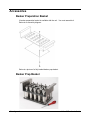
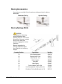


![12 place dishwasher 5 prog [ddw 175]](http://vs1.manualzilla.com/store/data/005678375_1-ad0b6eb6321fc485c4ee202ebc6e276f-150x150.png)