1
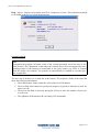
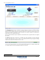
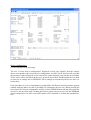
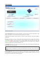
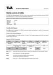
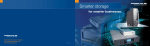
TDkit - The Configuration And Test Tool
TDkit
USER's GUIDE
CONFIGURATION AND TEST TOOL FOR
TANDBERG TAPE DRIVES AND AUTOMATION
PRODUCTS
TANDBERG DATA
ASA
P.O. Box 183 Økern
N-0510 OSLO,
NORWAY
Phone +47 22 18 90 90
Telefax +47 22 18 95 50
Part No.
43 33 28 - 06
TDkit - The Configuration And Test Tool
Table of contents:
Introduction........................................................................................................................................................................2
System Requirements........................................................................................................................................................2
Supported devices .............................................................................................................................................................3
Using TDkit.......................................................................................................................................................................4
Introduction
TDkit is a program that can be used to upload firmware, inspect and change some of the device
parameters and to execute some simple device operations. It also gives the operator the possibility
to perform tests that can be useful to check the reliability of the SCSI connection, the device and
the media.
The program has been tested thoroughly, but may still contain bugs and features that our testing
has not yet revealed. Tandberg Data is not responsible for any damage this program may cause.
We appreciate any comments and bug reports on this product.
For any known issues, see ReadMe.rtf in TDkit program folder.
System Requirements
TDkit runs in Windows 32-bit environments such as Win2000, Win2003 and XP. Under these systems it can be used either with the ASPI driver, which must be obtained separately, or Windows
native SCSI pass through interface (SPTI). The SPTI interface is part of the Windows NT platform and requires no installation.
The TDkit will use the ASPI driver if installed, otherwise the SPTI is used. However, even if the
ASPI driver is in place, use of SPTI may be forced by using a run time option SPTI in an shortcut
on the desktop. Or use the TDkit SPTI shortcut in Start\All Programs\TDkit directory:
TDkit with SPTI must be used in all Windows x64-bit environments (Win XP, Win 2003). There
is no ASPI support for the x64-bit Windows environment.
Note
Some systems already have drivers installed for the SCSI devices that may block the access for
TDkit driver. In this case it may be necessary to uninstall the device driver to allow access for
the TDkit driver.
Sometimes the tape device may be in use or reserved by some application or services. To avoid
this situation, the application or services using the device should be stopped or turned off before
the TDkit can be started.
One service to look for, when using Medium Changers, is the
Just stop the service temporarily before running TDkit.
Page 2 of 12
TDkit - The Configuration And Test Tool
Supported devices
•
TD StorageLoader
•
TD StorageLibrary T40
•
•
•
•
•
•
•
•
•
TDC 3500
TDC 3700
TR4
NS8 Pro
NS20 Pro
SLR2
SLR3
SLR4
SLR4DC
•
•
•
•
•
•
•
•
•
•
SLR5
SLR7
SLR24
SLR32
SLR40
SLR50
SLR60
SLR75
SLR100
SLR140
•
•
•
•
•
•
220LTO (LTO-1 HH)
420LTO (LTO-2 HH)
820LTO (LTO-3 HH)
840LTO (LTO-3 FH)
HPLTO (LTO-3 HH)
1640LTO(LTO-4 FH)
Page 3 of 12
TDkit - The Configuration And Test Tool
Using TDkit
During startup the TDkit detects and displays connected adapters and devices. The first tape
drive detected, if any, will be selected and available data displayed.
The upper part of the program panel shows the general information regarding the selected device and this part of the panel will always remain in sight.
The main menu on the top contains the following elements:
Page 4 of 12
TDkit - The Configuration And Test Tool
Function / Flash1 - if activated starts a dialog leading to replacement of the device firmware.
Function / SCSI rescan - gives the operator the possibility to rescan the SCSI bus, if new devices are connected or disconnected. Note that some operating systems do not support disconnecting of devices and a hang situation may then occur. A system restart is in some cases necessary to cure such situation.
Advice:
Do not remove devices unless you are certain that your system does support it.
Function / Detect tape2 - if checked (default), causes the program to periodically poll for
medium status changes and update the media related information on the screen automatically.
The default selection can be suppressed by using the run time option IDLE. In either case the
user may freely trigger/suspend the polling using this menu option.
Note
When polling is disabled, the Medium info button appears on the screen. Using this button
the user can manually update the medium information at any time.
Function / Exit, EXIT button and border icon ‘X’ in the top line, all close the program and
return to the operating system.
1
This function is supported since version 3.1
This function is only present in some earlier versions. Commencing with version 4.0 the media information is
automatically updated at program start, after a rescan, after a device selection and other relevant infrequent events.
2
Page 5 of 12
TDkit - The Configuration And Test Tool
Help / About - displays the program and all its component versions. This information should
be included each time you report program bugs.
General remarks
Note
Throughout the program execution, some of the controls presented on screen may be disabled at times. The explanation is that either the selected device does not support the corresponding feature or the function is unavailable in the given context (e.g. Erase or Unload
when the media is not loaded). The controls are automatically re-enabled as soon the function is applicable.
The user can at all times see a status bar at the bottom. The respective fields of the status bar
show the following information:
• The leftmost three fields contain the selected device SCSI address
• The next field either shows an operation in progress (in green) or indicates an error situation (in red)
• The next to last field is used only during the I/O test to show the number of bytes processed so far
• The rightmost field monitors the executing SCSI commands.
Page 6 of 12
TDkit - The Configuration And Test Tool
The tab selected pages3
Clicking the respective page tabs will display the different pages depending on the actions the
user wants, see below.
Device overview
See the snapshots above.
The detected devices are represented by icons indicating the device class. When holding the
cursor over an icon the device class and its full SCSI address appears as a hint. The currently
selected device has the icon framed in a blue square. Another device may be selected either by
clicking on its icon or by moving the selection frame about using the arrow keys.
Additional device info
The meaning of the “Cleaning flag status” is also displayed in text: “Cleaning not needed” in
green or “Cleaning needed” in red. Note that some older products like SLR2 – 5 do not support this information, others, e.g. TS400, only in part:
3
In earlier version the page tabs were located at the bottom.
Page 7 of 12
TDkit - The Configuration And Test Tool
The Memdump button causes a full drive memory dump to be taken over SCSI for failure
analysis. Before a dump is taken, the user must indicate the file where the dump will be saved.
Note that the dump is formatted in ASCII, but due to its specific contents it is basically intended only for the Tandberg Data staff.
Note also that the button may be disabled in case that the drive in question does not support
this facility.
The History Log4 button, which also is available only when applicable, provides important
account of the latest drive events. It takes a few moments before the log is prepared, during
which time the status line informs the user to wait:
As soon as the log generation is over, the log automatically appears in a separate window and
it’s contents may be saved at an arbitrary location as a text file:
4
Commencing with version 3.0 the print button of the History log is no longer supported.
Page 8 of 12
Device configuration
See the snapshot on the next page.
The text “Current device configuration” displayed on this page signifies that the settings
shown correspond to the current device configuration. In other words: this text tells you that
the parameter values displayed are the same as the values presently saved in the device RAM.
These values will be lost when the device is powered down. Most Tandberg Data devices hold
an extra set of settings also in EEPROM. These settings are assumed by the device after it is
powered up.
Each time these two sets of configuration settings differ, the Restore and Save buttons appears
enabled implying that a user has a possibility to synchronize the two sets. When pressing the
Save button, the current configuration will be saved in EEPROM and will thus be used at the
next boot. On the other hand, clicking the Restore button sets the device into the EEPROM
stored configuration. In either case both buttons will be disabled to confirm the synchronization.
Note:
The EOWR parameter makes the drive simulate old ½” tape drives. This is normally only
used in some Unix systems. Please refer to the SCSI programming manual for further information.
The button marked FW update facilitates device upgrade. When pushed, the user will be
prompted to locate the file with the applicable binary code, after which the flashing process
will commence. When completed, the device information on the screen will be automatically
updated. In case that the flashing fails (e.g. a corrupt or not applicable binary file was supplied) the user will be notified, but the device will not be affected.
Device operations
SCSI connection test writes and reads data to and from the tape device data buffer. This
makes it possible to verify whether the SCSI connection is reliable.
This test does not require a tape in the drive. If there is a tape in the drive, the data will not be
destroyed.
I/O test writes data to a tape, rewinds and reads the data back and compare them with the
write buffer contents. The test will run for several minutes and will show the result with
‘Passed’ or ‘Failed’. If the test fails, a corresponding SCSI error message will be displayed.
Hardware compression is disabled during the test.
Extended I/O test does the same as I/O test but will give the user an option to determine how
many MB to be written and read.
Note
This test expects a cartridge to be in the drive and the data on the tape, if any, will be overwritten.
Device diagnostics, when executed on behalf of a loader device, will load the drive from the
first magazine slot (note that, this slot must contain a writable cartridge), perform an I/O test
and return the cartridge back into the magazine.
When executed on behalf of a tape drive, the Device diagnostics test will perform the predefined selftest sequence 2 and run up to 50 minutes (drive dependent) and at the end will display the result with ‘Passed’ or ‘Failed’.
If the test fails, a corresponding SCSI error message will be displayed. The fault condition
will also result in flashing the amber failure led (the rightmost front drive led).
See the following manuals for more information:
430743 - TANDBERG SCSI INTERFACE FUNCTIONAL SPECIFICATIONS (Send Diagnostics)
430444 - TANDBERG SLR REFERENCE MANUAL (Selftest and Diagnostics)
Medium operations
Erase will perform a long (security) erase for SLR 2-5. For all other drives it will execute the
security erase only when the box above is checked.
Retention will perform a wind/rewind to end of tape and back to the beginning of tape, if applicable for the given device.
Unload will unlock the drive (if prevented by host) and eject the tape.
Note
SLR2-5 will be unlocked and logically unloaded (tape not available for application), but the
tape will not be physically ejected. To make the tape logically loaded the user must open
and close the drive door.
Default partition, if applicable, will reset the number of partitions on the tape to 1 to ensure
that the tape may be used to maximum capacity.