1
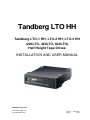
Tandberg LTO HH
Tandberg LTO-1 HH, LTO-2 HH, LTO-3 HH
(220LTO, 420LTO, 820LTO)
Half Height Tape Drives
INSTALLATION AND USER MANUAL
TANDBERG DATA ASA
www.tandbergdata.com
© Tandberg Data ASA
Part No.
August
433280-03
2007
Change log
Date
Author
Chapter
Change
22-Aug-05
WAJo
3.10
Added termination to the internal drive
16-Feb-06
WAJo
All
Added the Tandberg LTO-1 HH tape drive and TDkit.
Minor corrections
17-Aug-07
WAJo
All
Added in LTO-3HH (820LTO) and using Tandberg LTO
HH where all three products are covered.
Trademarks
LTO™ is a registered trademark of International Business Machines, Hewlett-Packard and Certance.
Windows 2000/2003/XP, Windows 95, Windows 98, MS-DOS, Windows
are registered trademarks of Microsoft Corporation in the United States.
All other trademarks are registered marks of their respective owners.
This publication may describe designs for which patents are granted or pending. By publishing this
information, Tandberg Data ASA conveys no license under any patent or any other rights.
Every effort has been made to avoid errors in text and diagrams. However, Tandberg Data ASA
assumes no responsibility for any errors, which may appear in this publication.
It is the policy of Tandberg Data ASA to improve products as new techniques and components
become available. Tandberg Data ASA therefore reserves the right to change specifications at any
time.
We would appreciate any comments on this publication.
Table of Contents
1.
Introduction ....................................................................................................................... 1
1.1
1.2
1.3
2
Specifications ..................................................................................................................... 3
2.1
2.2
2.3
2.4
2.5
2.6
3
3.9
3.10
3.11
3.12
Solution Contents .................................................................................................. 5
Tape Backup Software Installation ....................................................................... 5
Installation of Software Device Drivers ................................................................ 6
Mechanical Installation Internal Tape Drive ......................................................... 6
Mounting Screw Requirements ............................................................................. 6
SCSI Bus Interface ................................................................................................ 7
SCSI Controller Board Installation ....................................................................... 7
SCSI Configuration ............................................................................................... 8
3.8.1
SCSI-ID Selection Tandberg LTO HH Internal Tape Drive.................. 8
3.8.2
SCSI-ID Selection Tandberg LTO HH External Tape Drive................. 9
SCSI-bus Termination........................................................................................... 9
3.9.1
Termination in General ......................................................................... 9
3.9.2
SCSI-bus Termination – Internal Tape Drives .................................... 10
3.9.3
SCSI-bus Termination – External Tape Drives ................................... 10
Installation Internal Tape Drive .......................................................................... 11
External Tape Drive Installation ......................................................................... 11
Verifying Tape Drive Operation ......................................................................... 12
Tape Drive Operation ..................................................................................................... 13
4.1
4.2
4.3
4.4
5
Tape Drive Capacity and Performance.................................................................. 3
Media Specifications and Compatibility ............................................................... 3
Mechanical Dimensions ........................................................................................ 3
Power Requirements.............................................................................................. 3
Heat Dissipation .................................................................................................... 4
Data Compression ................................................................................................. 4
Tape Drive Installation ..................................................................................................... 5
3.1
3.2
3.3
3.4
3.5
3.6
3.7
3.8
4
Introduction to Tandberg LTO HH (Half Height) Series of Products ................... 1
Features and Benefits ............................................................................................ 1
How to Contact Tandberg Data Technical Support............................................... 2
Front LED Indicators .......................................................................................... 13
Tape Cartridge Operation.................................................................................... 13
4.2.1
Write Protecting the Cartridge............................................................ 14
4.2.2
Loading a Data Cartridge Into a Tandberg LTO HH ......................... 14
4.2.3
Ejecting a Data Cartridge From a Tandberg LTO HH....................... 15
Cleaning the Tape Drive...................................................................................... 15
4.3.1
Recommended Cleaning Interval......................................................... 15
4.3.2
Cleaning Procedure............................................................................. 15
4.3.3
Cleaning Cartridge Replacement ........................................................ 16
Handling and Storing LTO Cartridges ................................................................ 16
4.4.1
Handling LTO Cartridges ................................................................... 16
4.4.2
Storing LTO Cartridges....................................................................... 16
4.4.3
Storage Condition................................................................................ 16
Software Installation ....................................................................................................... 17
5.1
5.2
5.3
Windows 2000/2003/XP ..................................................................................... 17
5.1.1
Windows Tape Driver.......................................................................... 17
5.1.2
Windows Tape Driver Installation....................................................... 17
5.1.3
Windows Embedded Backup Application ............................................ 17
SCO Open Server ................................................................................................ 18
5.2.1
Host Adapter........................................................................................ 18
5.2.2
SCO Open Server System Commands.................................................. 18
5.2.3
SCO Open Server Backup Manager.................................................... 19
SCO UnixWare ................................................................................................... 19
Tandberg LTO HH Installation and User Manual
Tandberg Data
5.4
5.5
5.6
5.7
5.8
6
Contents
5.3.1
Host Adapter........................................................................................ 19
5.3.2
Installation........................................................................................... 19
5.3.3
SCO UnixWare System Command....................................................... 19
Sun Solaris .......................................................................................................... 20
5.4.1
Tape Drive Installation........................................................................ 20
5.4.2
Sun System Command.......................................................................... 20
IBM AIX ............................................................................................................. 21
5.5.1
Tape Drive Installation........................................................................ 21
5.5.2
IBM AIX System Command ................................................................. 21
5.5.3
IBM AIX Storage Manager.................................................................. 21
HP/UX................................................................................................................. 22
5.6.1
Tape Drive Installation........................................................................ 22
5.6.2
HP/UX System Command.................................................................... 22
Linux ................................................................................................................... 23
5.7.1
SCSI Host Adapter............................................................................... 23
5.7.2
Tape Drive Installation........................................................................ 23
5.7.3
Linux System Command ...................................................................... 23
Tape Drive Utilities............................................................................................. 24
5.8.1
FlashIt – Firmware Upgrade Utility ................................................... 24
5.8.2
TDkit – Tool for Testing and Downloading Firmware........................ 24
Troubleshooting............................................................................................................... 25
6.1
6.2
6.3
6.4
6.5
6.6
Hardware Checking............................................................................................. 25
Software Checking .............................................................................................. 25
Verifying Recent Changes................................................................................... 25
Standalone Diagnostics ....................................................................................... 25
6.4.1
Starting the Test................................................................................... 26
6.4.2
Test Sequence ...................................................................................... 26
6.4.3
Failure Indication................................................................................ 26
Media Management Reporting ........................................................................... 27
6.5.1
Cleaning is required ............................................................................ 27
6.5.2
Degraded Media.................................................................................. 27
Problem Situations .............................................................................................. 28
6.6.1
Dead on Arrival................................................................................... 28
6.6.2
Damaged Front Bezel.......................................................................... 28
6.6.3
Drive Not Detected by the Operating System (OS).............................. 29
6.6.4
Will Not Insert/Hold Media /Media is Not Recognized ....................... 29
6.6.5
Noisy Tape Drive................................................................................. 29
6.6.6
Cartridge is Stuck Inside the Drive ..................................................... 30
6.6.7
Fault LED Flashes Amber and the Activity LED is Off....................... 30
6.6.8
Fault LED Is Flashing Amber and the Activity LED Is Flashing........ 30
6.6.9
Cleaning LED Is ON ........................................................................... 31
6.6.10 Incorrect Data Compression ............................................................... 31
6.6.11 Slow Performance ............................................................................... 31
6.6.12 Intermittent Failures............................................................................ 31
6.6.13 Tape Removal Procedure .................................................................... 32
7
Glossary of Terms............................................................................................................ 33
8
App. A. LED-Indicator Behavior ................................................................................... 35
8.1
LED-behavior During Normal Operation............................................................ 35
Tandberg LTO HH Installation and User Manual
1. Introduction
Congratulations on your new Tandberg LTO HH tape storage solution!
Tandberg Data ASA is a leading global supplier of advanced, tape-based information data storage
products for the professional market. The company offers a wide range of products and solutions for
data protection and other user applications within data storage management.
Tandberg Data supplies tape drives and tape storage solutions to the world's leading OEMs and
through a worldwide channel sales network.
Total customer satisfaction is of the most importance to Tandberg Data. We guarantee that this
product left our premises defect free. If you are not satisfied with the quality of this product, please
contact your distributor, dealer or the nearest Tandberg Data office to have your problem resolved
quickly.
If you need technical support or have any problem with your LTO HH tape storage solution, phone,
fax and addresses can be found under www.tandbergdata.com SUPPORT.
On the following pages, before the installation guide starts, there is some brief information about the
Tandberg LTO HH tape storage solutions. Also listed is what is included with the Tandberg Data
product you have purchased.
All documentation referred to in this document is available as a downloadable PDF file from the
Tandberg Data web site:
www.tandbergdata.com
1.1 Introduction to Tandberg LTO HH (Half
Height) Series of Products
Tandberg Data now offers a whole rang of LTO tape and automation storage solutions from 200 GB
to 64 TB capacity and 115 GB/hr up to 864 GB/hr all assuming 2:1 data compressing. Please visit
www.tandbergdata.com for the complete offerings and for more details.
The LTO HH product range consists of:
•
LTO-1 HH (220LTO): 200 GB, 115 GB/hr
•
LTO-2 HH (420LTO): 400 GB, 173 GB/hr
•
LTO-3 HH (820LTO): 800 GB, 216 GB/hr
Designed for the SMB sector, Tandberg's LTO HH products are the ideal synthesis of efficiency,
modern innovation and maximum price/performance ratio. LTO's 6 generation roadmap, with 4
generations available today, makes it a clear choice for budget constrained small to medium
businesses. Choose a technology with future and guaranteed trouble-free data storage.
1.2 Features and Benefits
•
Up to 800 GB capacity and 216 GB per hour transfer rate.
•
Ultra160 SCSI interface provides ultimate performance of the SCSI bus
•
The LTO tape drives are backward compatible with oll older LTO formats. Coupled with the
LTO roadmap, this provides the best investment protection
•
Tandberg LTO-1 HH is a very affordable entry into the open standard LTO technology
offered by four manufacturers.
•
Embedded quality monitoring and test features provide preventive maintenance information
for reduced down time.
Tandberg LTO HH Installation and User Manual
1
Tandberg Data
•
Introduction
Low heat dissipation, small half-height 5.25-inch form factor with several mounting
capabilities for easy and trouble free integration into servers and workstations
1.3 How to Contact Tandberg Data Technical
Support
If you need technical support or have any problem with your LTO-1 HH or LTO-2 HH tape storage
solution, phone, fax and addresses can be found under www.tandbergdata.com SUPPORT.
2
Tandberg LTO HH Installation and User Manual
2 Specifications
2.1 Tape Drive Capacity and Performance
Tape Drive
Model
Tape Format
Capacity1)
Sustained Transfer
Rate1)
Interface Type
Tandberg
LTO-3 HH
Ultrium Gen. 3
400/800GB
30/60 MByte/sec
Ultra160
Ultrium Gen. 2
200/400GB
24/48 MByte/sec
Ultra160
Ultrium Gen. 1
100/200 GB
16/32 MByte/sec
Ultra160
Tandberg
LTO-2 HH
Ultrium Gen. 2
200/400 GB
24/48 Mbyte/sec
Ultra160
Ultrium Gen. 1
100/200 GB
16/32 MByte/sec
Ultra160
Tandberg
LTO-1 HH
Ultrium Gen. 1
100/200 GB
16/32 MByte/sec
Ultra 160
1) Capacity and transfer rate given in native/compressed (assuming 2:1 compression)
2.2 Media Specifications and Compatibility
Drive
Model
Tandberg
LTO-3 HH
Media Name
Tape
Length
Capacity
(Native)
Ordering
no.
LTO Ultrium Generation 3 (Native format)
680 m
400 GByte
43 32 16
LTO Ultrium Generation 2 (Read/Write compatible)
609 m
200 GByte
43 27 44
LTO Ultrium Generation 1 (Read compatible)
609 m
100 GByte
43 26 30
Tandberg
LTO-2 HH
LTO Ultrium Generation 2 (Native format)
609 m
200 GByte
43 27 44
LTO Ultrium Generation 1 (Read/Write compatible)
609 m
100 GByte
43 26 30
Tandberg
LTO-1 HH
LTO Ultrium Generation 1 (Native format)
609 m
100 GByte
43 26 30
2.3 Mechanical Dimensions
Standard drive mounting:
Fits in a 5.25-inch half-height (“slim-line”) enclosure for diskette, CD/DVD-rom or disk drive.
Standard mounting holes as for a half-height drive.
Dimensions (max.):
Height/width/depth: 41.3/146.0/214 mm (1.625/5.75/8.4 inch)
2.4 Power Requirements
Tandberg LTO-1, LTO-2, LTO-3 in external tabletop enclosure:
AC Input: 100 VAC / 0.6 A or 240 VAC / 0.3 A, 50-60 Hz
Tandberg LTO as standalone:
DC Input (typical operation) 5 VDC
DC Input (typical operation) 12 VDC
LTO-1/LTO-2
2.1 A
0.6 A
Tandberg LTO HH Installation and User Manual
LTO-3
0.8 A
0.7 A
3
Tandberg Data
Specifications
2.5 Heat Dissipation
Tandberg LTO as standalone:
Operating:
Sleep mode with cartridge inserted:
LTO-1/LTO-2
18 W
9W
LTO-3
13 W
6W
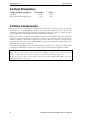
2.6 Data Compression
Data Compression is a way to increase capacity on a storage device. Compression ratios are normally
specified to be 2:1, meaning that it is possible to store twice as much data on the tape as without data
compression. However, the compression rate is depending on the type of data, e.g. ordinary text files
can be compressed in a much higher rate than program- and picture files.
There are two ways to compress data, hardware compression and software compression. Hardware
compression means that the data compression is done by the electronics in the storage device.
Software compression means that an application program in the host computer is compressing the
data before it is sent to the storage device. Hardware compression is much more efficient, and works
much faster than software compression.
The Tandberg LTO HH tape drives uses SLDC hardware compression to compress data. This feature
is enabled per default but the user may turn off data compression through the application software.
Note:
If the data are compressed by software in the host computer, and then sent to a device that does
hardware compression, the data have a tendency to expand instead of being compressed.
Be sure to turn the software data compression off if using the Tandberg LTO HH - which has
embedded hardware compression.
4
Tandberg LTO HH Installation and User Manual
3 Tape Drive Installation
3.1 Solution Contents
Note:
Please Check the Package Contents before Beginning the Installation and please check the label on
packing box for the actual content.
For Bare Drive:
•
Internal Tandberg LTO HH tape drive
•
Quick Installation Guide
•
Warranty card
For the Internal Kit and Solution:
•
Internal Tandberg LTO HH or LTO-3 HH tape drive
•
Internal SCSI cable
•
Removable LVD/SE terminator
•
Data cartridge (1 or 5 depending on type of kit/solution)
•
Application software (optional)
•
Quick Installation Guide
•
Warranty card
For the External Tabletop Kit and Solution:
•
Tabletop Tandberg LTO-1 HH or LTO-2 HH tape drive with power cord
•
External SCSI cable
•
External LVD/SE SCSI terminator
•
Data cartridge (1 or 5 depending on type of kit/solution)
•
Application software (optional)
•
Quick Installation Guide
•
Warranty card
3.2 Tape Backup Software Installation
You will need to install tape backup application software that supports the Tandberg LTO HH tape
drive. For the latest supported software version, please go to www.tandbergdata.com and select
SUPPORT, the actual LTO tape drive and select Compatibilities – or to the backup application
software vendor’s Web site.
For installation of tape backup application software, please refer to the software vendor’s installation
guide. Please also see section 5 in this document for installation of backup features embedded in the
operating systems.
Tandberg LTO HH Installation and User Manual
5
Tandberg Data
Tape Drive Installation
3.3 Installation of Software Device Drivers
If the backup application software does not detect the tape drive, or obtain the latest operating system
drivers and upgrades, please visit www.tandbergdata.com.
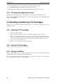
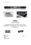
3.4 Mechanical Installation Internal Tape Drive
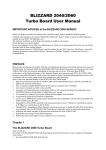
For mechanical mounting specifications, see Figure 3.2.
Allowed mounting position is either horizontal with the indicator LEDs to the right, or vertical with
the indicator LEDs up (see Figure 3.1).
Figure 3.1 Allowed mounting orientations
The drive occupies a half-height 5.25-inch slot with mounting screws on both sides
of the drive chassis or at the bottom of the drive.
Figure 3.2 Mounting specifications
3.5 Mounting Screw Requirements
6
•
Only M3 (metric) screws must be used for mounting the drive
•
Maximum permitted screw penetration:
2.5 mm
•
Minimum required screw penetration:
2.0 mm
•
Screw torque, mounting screws:
0.5 Nm
•
Screws are supplied with all the Tandberg LTO HH drive variants
•
Bag with 4 screws and 4 SCSI-ID jumpers
(Ordering no. 43 32 65)
Tandberg LTO HH Installation and User Manual
Tandberg Data
Tape Drive Installation
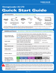
Do not use longer screws or higher screw torquethan specified!
Longer screws will bottom and not fasten the drive!
Wall of server
chassis
Safe penetration of mounting
screws: min 2 mm, max 2.5 mm
Tape drive's
mounting screw
Tape drive's
casting
Figure 3.3 Mounting screw details
3.6 SCSI Bus Interface
The Tandberg LTO HH tape drive is designed to operate on an Ultra160 low voltage differential
SCSI bus (LVD) with a burst transfer rate up to 160 MB/sec. The Ultra160 SCSI interface is
backward compatible with older SCSI interfaces. Thus all Ultra Wide may be used.
The tape drive features a high density 68-pin (HD-68) connector for attachment to the server or to the
interface connector in an external tabletop cabinet.
Attachment to the host computer is described below.
3.7 SCSI Controller Board Installation
Note:
Before any SCSI device can be installed it is necessary to have a SCSI controller board installed.
Please pay attention to the following points.
•
Make sure your computer is turn off before proceeding to the installation.
•
If you computer is equipped with an onboard SCSI controller, before proceeding with the
installation, you must first locate the SCSI connector on the computer motherboard.
Tandberg LTO HH Installation and User Manual
7
Tandberg Data
Tape Drive Installation
•
Refer to the documentation provided with your computer to find out where this connector is
located.
•
If multiple SCSI connectors are available, you can choose any of them, except if your
computer documentation mentions something different.
•
When done, firmly connect the SCSI connector to the Main-board connector and refer to
section 3.8 SCSI Configuration and 3.9 SCSI-bus Termination.
•
If your PC/Server needs a separate SCSI controller, you need to make sure it is properly
installed before connecting your Tandberg LTO HH tape drive.
•
You will also need a software driver from the SCSI controller vendor to activate the SCSI
Controller. Please make sure you have the latest software driver for your SCSI controller
loaded, and that the SCSI controller board is properly installed. Software drivers can be
downloaded from the vendors' web site. Refer to the README file for installation.
•
Please refer to the PC/Server documentation for further information on how to install
additional boards in the PC/Server. Or ask your local dealer for assistance.
3.8 SCSI Configuration
All devices on a SCSI-bus need their own unique identification, called SCSI-ID. If a SCSI-ID conflict
exists, some of the SCSI devices will not be recognized by your system. In many systems it is
common to use the SCSI-bus for the hard-drive and CD-ROM, as well as the tape drive. Remember
that the SCSI Controller uses SCSI-ID 7.
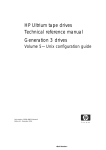
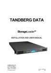
3.8.1 SCSI-ID Selection Tandberg LTO HH Internal Tape
Drive
The SCSI-ID on the Tandberg LTO HH is set by jumpers. From the table below, you can “read out”
which SCSI-ID the device has been set up for. All SCSI device ID's are displayed on the screen
during system startup.
Power Connector
Service Connector
SCSI Connector
Figure 3.4 Drive connectors, internal model
8
Tandberg LTO HH Installation and User Manual
Tandberg Data
Tape Drive Installation
SCSI-ID=0
SCSI-ID=1
SCSI-ID=2 (Default)
SCSI-ID=3
SCSI-ID=4
Example: SCSI-ID = 2
SCSI-ID=5
SCSI-ID=6
SCSI-ID=7
SCSI-ID=8
SCSI-ID=9
SCSI-ID=10
SCSI-ID=11
SCSI-ID=12
SCSI-ID=13
SCSI-ID=14
SCSI-ID=15
Table 3.1 Service Connector strap settings for SCSI-ID (Dark = Strap mounted)
If the tape drive is the only device on the SCSI bus, you do not need to do anything.
The tape drive will be recognized automatically. (All Tandberg Data tape drives are delivered with
SCSI-ID 2 as default.)
If the tape drive is going to share the SCSI-bus with other devices, check the SCSI-ID numbers used
by the other devices, then set the drive’s SCSI-ID to a number that is not being used by any of the
other devices (remember the SCSI host adapter uses ID 7)
3.8.2 SCSI-ID Selection Tandberg LTO HH External Tape
Drive
For the external tabletops, you will find the SCSI-ID setting thumb-wheel switch on the rear end of
the unit box:
SCSI-ID Switch
Figure 3.5 Drive connectors, external tabletop model
3.9 SCSI-bus Termination
3.9.1 Termination in General
A SCSI-bus is susceptible to interference, such as noise from electrical motors and other
electromagnetic devices. Also due to the speed of the data on the SCSI-bus, it is of outmost
importance to terminate the SCSI-bus properly. “Termination” is used to define the ends of the SCSIbus.
Tandberg LTO HH Installation and User Manual
9
Tandberg Data
Tape Drive Installation
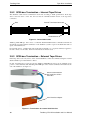
3.9.2 SCSI-bus Termination – Internal Tape Drives
The SCSI-bus cable must be terminated in both ends according to SCSI specifications. If the tape
drive is the last device on the bus, the bus must be terminated within 10 cm of the tape drive
connection.
Host
Internal Terminator Connector
10 cm
SCSI-bus
Last SCSI Device
Figure 3.6 Internal SCSI cable
Tandberg LTO HH tape drives have a combined SCSI-LVD/SE interface embedded. The PC-98
Specification specifies that the termination of the SCSI-bus system is a part of the SCSI-cable and not
a part of the SCSI-device.
For internal devices, a SCSI-cable with an integrated terminator or a separate terminator applied to
the end connector of the cable, 10 cm from the last device must be used.
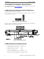
3.9.3 SCSI-bus Termination – External Tape Drives
If the Tape drive is the only device on the external SCSI-bus, it must be terminated using the external
SCSI termination provided with the solution.
If other external device(s) is/are present, the Tandberg LTO HH tape drives can be installed in any
position on the SCSI-bus. The Tandberg LTO HH tapes drive must be terminated if installed at the
end of the SCSI-bus. See figure 3.7:
External terminator on
the last device on the
SCSI bus
SCSI Interface adapter
Figure 3.7 Termination of external SCSI devices
10
Tandberg LTO HH Installation and User Manual
Tandberg Data
Tape Drive Installation
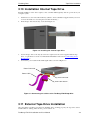
3.10 Installation Internal Tape Drive
Internal installation of the drive requires a free 5.25-inch half-height bay with an open front in your
computer system.
1.
Obtain access to the removable media bay. (Refer to the documentation supplied with your server
for more information on accessing the removable media bay.)
2.
Slide the tape drive into the bay, as shown in Figure 3.8.
Figure 3.8 Installing the internal tape drive
3.
Secure the tape drive to the bay. (If screws are required, use the screws supplied with the tape
drive, or equivalent. See Section 3.4 Mechanical Installation and Section 3.5 Mounting Screw
Requirements.)
4.
Connect the power cable and the SCSI signal cable, as shown in Figure 3.9.
Power Connector
Power Cable
SCSI Connector
SCSI Cable w/term
Figure 3.9 Connecting the cables to the Tandberg LTO HH tape drive
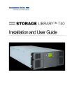
3.11 External Tape Drive Installation
After the SCSI controller board has been installed and is working properly, the tape drive can be
installed. Before starting, make sure the power is turned off.
Tandberg LTO HH Installation and User Manual
11
Tandberg Data
Tape Drive Installation
Please read carefully the Information about the SCSI-ID conflicts and SCSI termination in Sections
3.8 and 3.9.
Note: Do not apply or insert power cord until all connections have been made.
To install a tabletop tape drive, simply:
1.
Connect the tape drive to your PC/Server with the enclosed SCSI cable to any of the two
available SCSI connectors. Remember to place the termination on the free connector on the back
of the tape drive, and to select a unique SCSI-ID.
ON/OFF Switch
SCSI-ID Switch
SCSI Interface Connectors
Power Connector
Figure 3.10 Connecting the external Tandberg LTO HH tape drive
2.
Connect it to the power outlet.
3.
When you power up the system for the first time, check that all your SCSI devices are recognized
by the SCSI controller board.
3.12 Verifying Tape Drive Operation
Once you have installed the Tandberg LTO HH tape drive hardware to the host computer, verify that
it is functioning properly before you attempt to store data.
1.
For internal drives: Switch on the host computer
2.
For external drives: Switch on the drive before switching on the host computer
3.
The Tandberg LTO HH tape drive starts a power-on selftest exercising most of the drive’s
functionality without requiring any cartridge to be inserted.
4.
All the four LEDs light during power-up (see section 4.1 Front LED Indicators).
5.
The Activity LED is flashing during the selftest operation.
6.
If any error occurs during the selftest, the tape drive will flash the Fault LED.
7.
All LEDs are off after the selftest is performed successfully
8.
If a tape cartridge is inserted, the tape cartridge will be loaded and the Ready LED will be lit.
12
Tandberg LTO HH Installation and User Manual
4 Tape Drive Operation
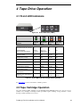
4.1 Front LED Indicators
Figure 4.1 Status indicators (LEDs)
READY LED
(Green)
Drive State
LED-test.
The LEDs are turned ON in sequence ON
ACTIVITY LED
(Green)
CLEAN LED
(Amber)
FAULT LED
(Amber)
ON
ON
ON
Power-On Self-Test
Starts in parallel with the LED-test .
Flashing in
about 12 sec
After 12 sec:
Flashing during
cartridge load
OFF
OFF
Cartridge not loaded.
OFF
OFF
ON / OFF
OFF
Cartridge loaded, no activity
ON
OFF
ON / OFF
OFF
Cartridge loaded, activity
ON
Flashing
ON / OFF
OFF
Cleaning
OFF
Flashing
ON
OFF
Cartridge loading or unloading
OFF
Flashing
ON / OFF
OFF
Unrecoverable drive failure
ON / OFF
OFF
ON / OFF
Flashing
Over temperature
OFF
OFF
ON / OFF
ON
Media Error (wrong, write protected or
harmed media)
OFF
Flashing
ON / OFF
Flashing
Table 4.1 Front LED behaviour during normal operation
See Appendix A for more information on LED operation
4.2 Tape Cartridge Operation
Use only certified quality cartridges for the Tandberg LTO HH Tape Drives. Do not use worn or
audibly noisy cartridges. Cartridges which repeatedly require rewriting of large numbers of datablocks per track should also be rejected.
Tandberg LTO HH Installation and User Manual
13
Tandberg Data
Tape Drive Operation
4.2.1 Write Protecting the Cartridge
The LTO cartridge can be write-protected by operating the write protect switch.
The Tandberg LTO HH tape drive detects that the write-protect switch is set and then not allow any
writing on the tape.
Tape Window
Arrow for
cartridge
orientation
The Write Protect switch of the LTO cartridge is shown in the
non-protected position.
When the cartridge is write protected, the switch is to the right
and the area is red.
Figure 4.2 LTO cartridge write protect switch
4.2.2 Loading a Data Cartridge Into a Tandberg LTO HH
The cartridge must be inserted with the label facing up and the tape dust cover towards the LEDs. The
drive has Semi-Soft Load: Slide the cartridge slowly into the Drive until it stops then let go. Then the
cartridge is detected and a motor-driven load mechanism locks the cartridge automatically in the
correct position.
In order not to damage the drive or the cartridge:
•
DO NOT use extensive force
•
BE SURE to insert the cartridge in correct position
•
Be sure to insert the cartridge all the way in until a HARD stop
1.
Ensure that the LTO cartridge is correctly oriented with the arrow on the cartridge pointing up
and towards the tape drive (see Figure 4.2 for tape orientation).
2.
Push the cartridge firmly into the tape drive until the point of hard stop and remove your hand.
The tape drive starts loading.
3.
In case the drive will not hold the cartridge allow the cartridge to eject and settle completely.
Wait for the Activity indicator (see Section 4.1) to turn off. Repeat the sequence from step 1.
Figure 4.3 Cartridge insertion
14
Tandberg LTO HH Installation and User Manual
Tandberg Data
Tape Drive Operation
4.2.3 Ejecting a Data Cartridge From a Tandberg LTO HH
The cartridge can be ejected either by pressing the eject button located on the drive’s front panel, or
by an Unload SCSI command. The drive automatically rewinds and ejects the cartridge (Soft Unload).
When removing the cartridge, wait until the soft-eject function has terminated its operation. Then pull
the cartridge straight out.
Eject button
Figure 4.4 Location of the eject button
4.3 Cleaning the Tape Drive
Prior to use, the LTO cleaning cartridge should be adapted to the operating environment for a time at
least equal to the period it has been out of the operating environment and outside or above 10ºC –
35ºC (up to a maximum of 24 hours). Recommended operating temperature is 25ºC/77ºF or below
(see tape drive specifications).
4.3.1 Recommended Cleaning Interval
The Clean LED steady ON indicates that a head cleaning operation is recommended (the drive is still
fully operational with this LED steady ON) the LED is triggered after 100 hours of tape running time
has elapsed, if the Media Management Algorithm has detected severely degraded write performance,
or if a hard read/write error has occurred. The LED is not turned off by a power cycle. The LED is
reset when cleaning has completed successfully.
Note: For the Tandberg LTO HH, cleaning is required when the cleaning LED (third from left) lights
steady amber.
Always clean the head if large numbers of rewrite- or reread operations are performed. The head
should also be immediately cleaned if hard Read or Write errors occur.
4.3.2 Cleaning Procedure
1.
Load the cleaning cartridge into the LTO HH tape drive.
2.
The cleaning process will begin automatically. This is indicated by the front LEDs on the product
as follows:
ACTIVITY LED (no 2
from left) is flashing
GREEN
CLEANING LED (no 3 from
left) is steady AMBER
Figure 4.5 Activity and Cleaning LEDs
Tandberg LTO HH Installation and User Manual
15
Tandberg Data
Tape Drive Operation
3.
The cartridge will be ejected when cleaning has completed (about 3 minutes).
4.
The CLEANING LED will be OFF if the cleaning was successful.
5.
If the cleaning was NOT successful, the CLEANING LED will stay ON. See below
4.3.3 Cleaning Cartridge Replacement
The LTO Cleaning Cartridge can be used about 50 times in the Tandberg LTO HH tape drive.
Replace the LTO HH Cleaning Cartridge if it is ejected from the tape drive and the CLEANING LED
is still constant AMBER.
4.4 Handling and Storing LTO Cartridges
To improve data reliability and LTO cartridge lifetime, it is important to handle and store the
cartridges properly.
4.4.1 Handling LTO Cartridges
•
Do not drop LTO cartridges
•
Make sure the air around the tape drive and the LTO cartridge storage area is clean
•
Prior to use, the LTO cartridge should be adapted to the operating environment for a time at
least equal to the period it has been out of the operating environment outside and above 10ºC
– 35ºC (up to a maximum of 24 hours). Recommended operating temperature is 25ºC or
below (see tape drive specifications).
•
Replace worn or excessively noisy LTO cartridges
4.4.2 Storing LTO Cartridges
An LTO cartridge is best stored in its protective case.
4.4.3 Storage Condition
Store the LTO cartridge in a cool and dry environment. Avoid high temperatures. Recommended
maximum temperature is 25ºC/77ºF and 50 % RH humidity.
Do not store the LTO cartridge near devices such as computer monitors, TV sets, or loudspeakers
with strong magnetic fields (not exceeding 4000A/m).
16
Tandberg LTO HH Installation and User Manual
5 Software Installation
This chapter contains information for installing tape drives in the following operating system
environments:
•
Windows 2000/2003/XP
•
SCO Open Server
•
SCO UnixWare
•
Sun Solaris
•
IBM AIX
•
HP UX
•
Linux
Please see www.tandbergdata.com SUPPORT, [Product], Compatibility for the most current backup
application software compatibility information.
5.1 Windows 2000/2003/XP
5.1.1 Windows Tape Driver
The Tandberg LTO HH requires an additional tape driver that is available from the Tandberg website
at www.tandbergdata.com.
5.1.2 Windows Tape Driver Installation
1.
Right-click on My Computer.
2.
Select Manage, you should see the tape drive under “Other devices” with a “?”.
3.
Select the device, right click and Properties.
4.
Select the appropriate driver location.
5.
Follow the instructions on the screen.
5.1.3 Windows Embedded Backup Application
The Backup application is included in the Windows Operating System.
Before running the application, make sure the tape driver for your Tandberg LTO HH tape drive is
properly installed. See Section 5.1.2.
To start the application:
1.
Click on START.
2.
Click on Programs.
3.
Click on Accessories.
4.
Click on System tools.
5.
Select Backup.
Tandberg LTO HH Installation and User Manual
17
Tandberg Data
Software Installation
5.2 SCO Open Server
5.2.1 Host Adapter
SCO OS includes a driver for most SCSI host adapters.
If you can not find the appropriate driver, please refer to the installation guide provided with the SCSI
interface adapter.
To install the host adapter:
1.
Login as root.
2.
Type the following command: MKDEV TAPE.
3.
Select Install a SCSI Tape Drive.
4.
Enter the prefix of the SCSI host adapter that supports this device.
(Typing h gives you a list of the supported SCSI host adapter)
5.
Which SCSI host adapter supports this device?
If only one SCSI host adapter in installed select 0. If two SCSI host adapters of the same type are
installed, select 1
6.
What is the target ID for this device? (2 is the Tandberg default SCSI-ID)
7.
What is the LUN of this device? (Must be set to 0).
8.
Update the SCSI Configuration?
Check first that the table on the screen is conformed to the Tape Drive configuration.
9.
Press Return for the next three questions to use the default settings.
10. Select Tape Device Types. Choose 1 for Generic SCSI-1/SCSI-2 tape drive.
Note: The Kernel has to be rebuilt to reflect the new Hardware configuration, and a reboot is
mandatory before you can use your LTO tape drive.
For any questions related to this operating system or its embedded Backup applet, please refer to the
documentation provided on the SCO OS CD-ROM.
5.2.2 SCO Open Server System Commands
TAR, CPIO and DD allow simple backup, verify or restore operations to be performed.
Two different device drivers can be used:
•
A Non Rewind device driver (used to perform append Backup)
•
A Rewind device driver (used only to perform overwrite backup)
For a complete explanation on how to use the system commands, please refer to the SCO Open Server
documentation, or the online help. (MAN command).
Tar command examples:
tar cvf /dev/rStp0 /etc will perform the backup of the /etc directory
tar tvf /dev/rStp0 will read the data on the tape
tar xvf /dev/rStp0 will restore the data from the tape to the current directory tree
18
Tandberg LTO HH Installation and User Manual
Tandberg Data
Software Installation
5.2.3 SCO Open Server Backup Manager
SCO Open Server Graphic Interface
1.
Click on System Administration.
2.
Double-click on Backup Manager.
3.
Follow the instructions on the screen
SCO Open Server Console
1.
Login as Root.
2.
Type SCOADMIN.
3.
Select Backup Manager.
5.3 SCO UnixWare
5.3.1 Host Adapter
SCO UnixWare includes a driver for most SCSI host adapters.
If the appropriate driver cannot be found, please refer to the installation guide provided with the SCSI
host adapter.
5.3.2 Installation
1.
Install the Tandberg LTO HH tape drive.
2.
Turn on the PC.
3.
During the boot process, SCO UnixWare automatically detects the LTO HH and installs the
correct tape driver.
Note: For any questions related to this operating system or its embedded Backup applet, please refer
to the documentation provided on the SCO CD-ROM.
5.3.3 SCO UnixWare System Command
TAR, CPIO and DD allow simple Backup, Verify or Restore operations to be performed.
Two different device drivers can be used:
• A Non Rewind device driver (used to perform append backup)
• A Rewind device driver (used only to perform overwrite backup)
For a complete explanation on how to use the system commands, please refer to the SCO UnixWare
documentation, or the online help. (MAN command).
Tar command examples:
tar cvf /dev/rmt/c0s0 /etc performs the backup of the /etc directory
tar tvf /dev/rmt/c0s0 reads the data on the tape
tar xvf /dev/rmt/c0s0 restores the data from the tape to the current directory tree
Tandberg LTO HH Installation and User Manual
19
Tandberg Data
Software Installation
5.4 Sun Solaris
5.4.1 Tape Drive Installation
1.
Install the Tandberg LTO HH Tape Drive.
2.
Turn on the SUN workstation or server.
3.
Use rm –f /dev/rmt/* to remove any reference to old tape device, and then use devfsadm –c tape.
This reconfigures the /dev/rmt directory for the LTO HH to work properly on the machine.
For improved performance using the Tandberg LTO HH, a specific system file can be modified:
/kernel/drv/st.conf
ST.CONF File entries for Tandberg LTO HH:
"TANDBERGTS400", "Tandberg LTO-2 HH LTO", "TANDBERG_TS400";
TANDBERGTS200", "Tandberg LTO-1 HH LTO", "TANDBERG_TS200";*
TANDBERG_TS400 =1,0x36,0,0x9639,3,0x00,0x40,0x42,2;
* Will be “TANDBERG_TS400” until TBA
5.4.2 Sun System Command
TAR, CPIO and DD allow simple Backup, Verify or Restore operations to be performed.
Two different device drivers can be used:
• A Non Rewind device driver (used to perform append backup)
• A Rewind device driver (used only to perform overwrite backup)
Tar command examples:
tar cvf /dev/rmt/0cb /etc performs the backup of the /etc directory
tar tvf /dev/rmt/0cb reads the data on the tape
tar xvf /dev/rmt/0cb restores the data from the tape to the current directory tree.
For a complete explanation on how to use the system commands, please refer to the Sun
documentation, or the online help. (MAN command).
20
Tandberg LTO HH Installation and User Manual
Tandberg Data
Software Installation
5.5 IBM AIX
5.5.1 Tape Drive Installation
To install any of the Tandberg LTO HH tape drives on IBM AIX, the smit utility must be used.
1.
Be sure the SCSI-ID of the tape drive is not used in the SCSI Sub-System.
2.
Install the LTO HH tape drive.
3.
Login as root.
4.
Run smit devices.
5.
Select Tape Drive.
6.
Follow the instructions on the screen.
For improved performance on LTO HH, the default block size should be set to 0 and the density to
default LTO type :
1.
Run smit devices.
2.
Select Change/Show characteristics of a tape drive.
3.
Select the tape driver you want to modify.
4.
Set the BLOCK size to 0
5.
You can set the density codes that the LTO HH support by enter the value of 66 & 64 (0x42 for
LTO2 and 0x40 for LTO1) in the field DENSITY setting #1 & #2 respectively.
5.5.2 IBM AIX System Command
TAR, CPIO and DD allow simple Backup, Verify or Restore operations to be performed.
Two different device drivers can be used:
• A Non Rewind device driver (used to perform append backup)
• A Rewind device driver (used only to perform overwrite backup)
Please refer to the IBM AIX documentation for more information.
Tar command examples:
tar cvf /dev/rmt0 /etc performs the backup of the /etc directory
tar tvf /dev/rmt0 reads the data on the tape
tar xvf /dev/rmt0 restores the data from the tape to the current directory tree
5.5.3 IBM AIX Storage Manager
This application is part of the operating system. Install as follows:
1.
Open the System Administrator window.
Tandberg LTO HH Installation and User Manual
21
Tandberg Data
Software Installation
2.
Double-click on Storage Manager.
The list of available tape device(s) appears on the screen.
3.
Follow the instructions on the screen to continue
Note:
For any questions related to this application or its installation, please refer to the IBM online
documentation
.
5.6 HP/UX
5.6.1 Tape Drive Installation
To install the Tandberg LTO HH tape drives, use the SAM utility.
1.
Login as root.
2.
Run SAM.
3.
Select Peripheral Devices.
4.
Select Action/Add.
The Tandberg LTO HH is automatically detected and the necessary drivers installed.
5.6.2 HP/UX System Command
TAR, CPIO and DD allow simple Backup, Verify or Restore operations to be performed.
Two different device drivers can be used:
• A Non Rewind device driver (used to perform append backup)
• A Rewind device driver (used only to perform overwrite backup)
Tar command examples:
tar cvf /dev/rmt0 /etc performs the backup of the /etc directory
tar tvf /dev/rmt0 reads the data on the tape
tar xvf /dev/rmt0 restores the data from the tape to the current directory tree
For a complete explanation on how to use the system commands, please refer to the HPUX
documentation, or the online help. (MAN command).
22
Tandberg LTO HH Installation and User Manual
Tandberg Data
Software Installation
5.7 Linux
5.7.1 SCSI Host Adapter
Linux contains a driver for most SCSI host adapters.
If the driver cannot be found, please refer to the documentation provided with the SCSI host adapter.
5.7.2 Tape Drive Installation
1.
Install the Tandberg LTO HH Tape Drive.
2.
Turn on the PC.
3.
During the boot process, Linux automatically detects the LTO HH and installs the correct tape
driver.
For improved performance using the Tandberg LTO HH, a specific system file can be modified:
/etc/stinit.def
stinit.def File entries for Tandberg LTO HH:
manufacturer="TANDBERG" model = "TS400" {
scsi2logical=1
can-bsr=1
auto-lock=0
two-fms=0
drive-buffering=1
buffer-writes
read-ahead=1
async-writes=1
can-partitions=1
fast-mteom=1
mode1 blocksize=0 density=0x42 compression=1 # 400 GB, native
mode2 blocksize=0 density=0x42 compression=0 # 200 GB, LTO
}
Note:
For any questions related to this operating system or its embedded backup applet, please refer to the
documentation provided on the Linux CD-ROM.
5.7.3 Linux System Command
TAR, CPIO and DD allow simple Backup, Verify or Restore operations to be performed.
Two different device drivers can be used:
• A Non Rewind device driver (used to perform append backup)
• A Rewind device driver (used only to perform overwrite backup)
Tar command examples:
Tandberg LTO HH Installation and User Manual
23
Tandberg Data
Software Installation
tar cvf /dev/st0 /etc performs the backup of the /etc directory
tar tvf /dev/st0 reads the data on the tape
tar xvf /dev/st0 restores the data from the tape to the current directory tree
For a complete explanation on how to use the system commands, please refer to the Linux
documentation, or the online help. (MAN command).
5.8 Tape Drive Utilities
On www.tandbergdata.com under SUPPORT, [Product], Software, the following software tool can be
found:
5.8.1 FlashIt – Firmware Upgrade Utility
This utility is used for updating the LTO HH firmware.
FlashIt is a simple program that can be used to upgrade the microcode in the Tandberg Data range of
tape drives and in Tandberg Data Autoloaders and Libraries. FlashIt communicates with the devices
through their SCSI interface.
FlashIt automatically finds all supported SCSI devices in your system (not disks). FlashIt also guides
you in locating microcode files and gives you an indication of which microcode files can be used to
upgrade the selected device.
FlashIt comes in separate versions for DOS, Windows 95/98/ME and Windows NT/2000/2003/XP.
Note:
For more information, please see the User Guide available on the www.tandbergdata.com select
SUPPORT, [Product], Software
5.8.2 TDkit – Tool for Testing and Downloading Firmware
TDkit is a program that can be used to inspect and change some of the tape drives parameters and to
execute some simple tape operations. It also gives the operator the possibility to perform a few tests
that can be useful to check the reliability of the SCSI connection, the tape drive and the media. Finally
it can be used to upgrade the drive fw and perform a data dump for deep analyses.
TDkit can be downloaded from www.tandbergdata.com – select SUPPORT, [Product], Software
24
Tandberg LTO HH Installation and User Manual
6 Troubleshooting
In case of problems with operation of your Tandberg LTO HH tape drive and before contacting the
Customer Services Group, please be sure to check the following:
6.1 Hardware Checking
1.
Check that the system recognizes the tape drive during the boot process.
2.
Check that the SCSI host adapter recognizes the tape drive during its initialization.
3.
Check the tape drive Front Panel LED status.
4.
Check that the SCSI-ID of the drive is not conflicting on the SCSI-bus.
5.
Check that the power cable is inserted correctly.
6.
Check that the SCSI cable connections including termination are made correctly.
6.2 Software Checking
1.
Check that the operating system does not report a problem during the boot.
2.
Check that the driver for the SCSI host adapter is present and loaded properly.
3.
Check that the correct Tape Device Driver has been installed properly - if applicable.
4.
Check that the Backup software does not report any error messages when loading.
5.
If any problem occurs, reinstall the Backup Application Software and check that the LTO-2 HH
is recognized.
6.3 Verifying Recent Changes
If the Tandberg LTO HH has been installed previously and operating correctly but is now incurring a
problem, verify any recent changes to the system to ensure that these changes are not causing the
problem. Try the following:
1.
If the system configuration has changed:
Remove the change to see if it affected the tape drive.
2.
If an operating system corrective patch has been installed:
Remove it to see if it affected the tape drive.
3.
If a SCSI device has been added:
Check for SCSI-ID conflicts.
4.
If a SCSI device has been added:
Check if the SCSI termination has been properly set.
6.4 Standalone Diagnostics
The main objective for the Standalone Diagnostics test is to test the complete drive as comprehensive
and fast as possible without any drive configuration or host support. The tool can also be used to
verify tapes.
Tandberg LTO HH Installation and User Manual
25
Tandberg Data
Troubleshooting
6.4.1 Starting the Test
A Standalone Diagnostic test requires a tape that is not write-protected. The media type can be any
media type that supports a tape format that can be written by the drive.
CAUTION: Since the test involves write operations, the existing tape contents will be destroyed!
1.
Make sure that no cartridge is loaded.
No cartridge should be loaded at this stage. If a cartridge is loaded it can be ejected by clicking
the Eject Button.
2.
Enter Service Mode by keeping the Eject Button pressed for at least 6 seconds.
The Ready LED (on the left) starts flashing fast (indicating the drive is in Service Mode and that
Service entry number 1 is active).
3.
Insert the tape cartridge into the drive within 15 seconds.
The drive loads the cartridge and the Ready LED starts flashing indicating that Standalone
Diagnostics has started. The eject button has now returned to normal mode. During the
Standalone Diagnostics test, it is possible to abort the test and eject the cartridge by clicking the
eject button. The drive indicates the detection of the abort request by flashing both the Ready and
Activity LEDs. Depending on at which stage the test is aborted, it may take a while before the
drive starts the eject operation. When the cartridge has been ejected, all LEDs are turned off (the
Cleaning LED may however be on).
The Ready LED will continue flashing during the complete test. The Activity LED will be
flashing when the test performs tape motion.
If no cartridge has been inserted after 15 seconds, the LEDs revert back to their initial state and
the Eject Button must be pressed for 6 seconds again to get back to Service Mode.
6.4.2 Test Sequence
The Tandberg LTO HH Standalone Diagnostics test will perform the following operations:
Collect Information. Reads and stores drive and medium information:
• Firmware and Drive ID
• Tape type and format
• Cartridge serial number
• Error History Log and Log page 0x33 from EEPROM
• Run-time counters from EEPROM
Mainboard Test. Tests the mainboard hardware.
Cartridge Manipulation Test. The Cartridge Manipulation Test performs the same mechanical
movement operations as those performed during Cartridge Load and Eject.
Read/Write Test. This test involves actual reading and writing on the tape medium. A write pass and
a read pass are executed.
When the test has completed without errors the tape cartridge is ejected. No LEDs will be lit (the
Cleaning LED may however be on).
6.4.3 Failure Indication
When a failure has been detected the tape is not ejected and the Failure LED will be flashing.
Detailed information can be retrieved by the ‘Receive Diagnostic Results’ SCSI command.
26
Tandberg LTO HH Installation and User Manual
Tandberg Data
Troubleshooting
If a write protected, unsupported, or damaged tape cartridge is inserted in order to start the Standalone
Diagnostics test, it will be ejected by the drive and the Failure and Activity LEDs will be flashing
while the Ready LED is off. The two flashing LEDs can be turned off by clicking the Eject Button.
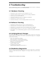
6.5 Media Management Reporting 1
Media Management (MM) is a feature embedded in the Tandberg LTO HH tape drive’s firmware that
monitors the read and write performance of the tape drive and media. Write performance information
is written on the media header every time the media is rewound, and before the media is unloaded.
6.5.1 Cleaning is required
If the write performance is below a factory set re-write threshold, the Tandberg LTO HH reports that
cleaning is required.
Tandberg LTO HH reports that cleaning is required by setting the Clean LED to steady AMBER, and
sending information to the backup application software using the SCSI Tape Alert reporting standard.
Figure 6.1 Backup Exec reporting that the tape drive needs cleaning
TAPE
***TapeAlert*** The following information is for Device[0]:
TAPE
E6918 The tape drive needs cleaning:
1. If the operation has stopped eject the tape and clean the drive.
2. If the operation has not stopped wait for it to finish and clean the
drive.
Check user’s manual for cleaning instructions.
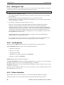
Figure 6.2 ARCserve reporting that the tape drive needs cleaning
If the Tandberg LTO HH works normal after cleaning, both media and tape drive are good.
6.5.2 Degraded Media
If the write performance is still below the re-write threshold after cleaning, MM reports via the Clean
Tandberg LTO HH Installation and User Manual
27
Tandberg Data
Troubleshooting
LED (set to steady AMBER) and the backup application software that the media is degraded.
Figure 6.3 Backup Exec reporting that the media is degraded
The degraded media warning is a warning that the cartridge is less safe, and if it continues to be used,
it may become worn to the point where drive cannot write or read successfully using this cartridge.
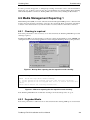
TAPE
***TapeAlert*** The following information is for Device[0]:
TAPE
E6913 Your data on tape[10/26/01 1:25 PM] serial number[303145]
is at risk.
1. Copy any data require from this tape. Do not use this tape again.
2. Restart operation with a different tape.
Figure 6.4 ARCserve reporting that the media is degraded
6.6 Problem Situations
6.6.1 Dead on Arrival
1.
Check LED activity at power up.
All four LEDs flash for two seconds at power up and the Ready LED flashes for several seconds
while the power-on self test is running.
2.
Make sure that the power supply used is working:
Measure with an external voltmeter or use a verified supply.
3.
Perform “drive dead test” when supply is verified.
Push the eject button for at least 6 seconds to enter the “drive dead test”. The Activity LED
should keep flashing for approximately 15 seconds.
If the drive still looks dead try to remove all cable except power and redo “drive dead test”, a
defective cable or SCSI host bus adapter may leave the drive in a reset condition.
6.6.2 Damaged Front Bezel
There are no electrical parts or cables in the front bezel.
1.
28
Eject and remove any cartridge in the drive before replacing the front bezel.
Tandberg LTO HH Installation and User Manual
Tandberg Data
Troubleshooting
2.
Remove the damaged front bezel.
Use a small flat screwdriver or your fingernails to lift the small plastic “ears” on each side of the
drive.
3.
Install the new bezel.
Push it gently onto the front of the drive until the “ears” snap into place on each side.
6.6.3 Drive Not Detected by the Operating System (OS)
1.
Check LED activity at Power Up
All four LEDs flash for two seconds at power up and the Ready LED flashes for several seconds
while the power-on self test is running.
2.
Check the SCSI-ID
Each device on the SCSI bus needs a unique SCSI-ID. The SCSI-ID is set with jumpers on the
backside of the drive. See label on drive, the installation guide supplied with the tape drive, or on
the web for instructions.
3.
Check SCSI termination
The SCSI bus should be terminated at the end of the cable; a defective terminator may leave the
drive in a reset condition.
6.6.4 Will Not Insert/Hold Media /Media is Not Recognized
1.
Check cartridge type.
Tandberg LTO-3 HH will only accept LTO-1, LTO-2 or LTO-3 type data or cleaning cartridges.
Tandberg LTO-2 HH will only accept LTO-1 or LTO-2 type data or cleaning cartridges.
Tandberg LTO-1 HH will only accept LTO-1 or cleaning cartridges.
If a wrong type of cartridge is inserted, it can be mechanically prevented from being inserted or
electrically rejected after insertion.
2.
Check media orientation.
The arrow on the cartridge must point into the tape drive facing up when the tape drive is
mounted horizontally with the LEDs on the right.
Media can be inserted only the “correct way”; there are mechanical blockings if the media is
insert wrong.
3.
Try using a new cartridge.
If it loads correctly, check the failing cartridge for damage.
4.
Check failing media for pin damage (buckling pin).
Hold the cartridge in your hand with the Write Protect Switch to your left and orientation arrow
pointing from you. On the right side all the way in front is a small door that can be opened by
sliding a door against you. Inside the cartridge you should see a metal pin, the pin shall be
parallel with the cartridge front and is hold in place by to metal grippers at each end (top and
bottom of the cartridge). The media should be attached to this pin, and you see only the top and
bottom part of the pin.
If the pin is missing, loose or damaged the tape will be damaged and rejected from the drive.
6.6.5 Noisy Tape Drive
There are no fans in the Tandberg LTO HH tape drive and the noise should be very low in idle mode.
When the tape moves the noise can come from the media itself. The drive will give a steady sound
when streaming. The sound is “intermittent” if the host is not delivering data at the data rate of the
drive.
1.
Check if the noise comes from the cartridge.
Insert new media – first check this media for any damage.
Tandberg LTO HH Installation and User Manual
29
Tandberg Data
2.
Troubleshooting
Check that the Tandberg LTO HH is mounted correctly.
If the Tandberg LTO HH is mounted incorrectly, it can produce noise when the tape moves.
6.6.6 Cartridge is Stuck Inside the Drive
1.
Try to eject the cartridge by pushing the eject button
2.
Do a drive reset using the Service mode.
Service mode is entered by keeping the eject button pressed for at least six seconds. The Activity
LED starts flashing.
3.
To reset the drive, push the eject button once more to make the Activity LED flash. While this
LED is flashing, double-click the eject button. This should make the drive do a reset.
4.
If the button is not pushed for 15 seconds, the eject button reverts back to its original cartridge
eject function.
5.
Power cycle the drive (switch power on/off, if possible).
6.6.7 Fault LED Flashes Amber and the Activity LED is Off
The tape drive reports that it has a failure.
1.
Do a Drive reset using the Service mode.
Service mode is entered by keeping the eject button pressed for at least six seconds. The Ready
LED will start flashing.
To reset the drive, push the eject button once more to make the Activity LED flash. While this
LED is flashing, double-click the eject button. This should make the drive do a reset.
If the button is not pushed for 15 seconds, the eject button reverts back to its original cartridge
eject function.
2.
Power cycle the drive (switch power on/off, if possible).
6.6.8 Fault LED Is Flashing Amber and the Activity LED Is
Flashing
The drive signals Media Error.
To eject the cartridge, press the Eject button
1.
Check if the media is correct.
2.
Check the write protection switch position.
3.
Check if the media is damaged (see also Section 6.6.4).
4.
Check if an expired cleaning cartridge was used (Clean LED is On)
30
Tandberg LTO HH Installation and User Manual
Tandberg Data
Troubleshooting
6.6.9 Cleaning LED Is ON
The Cleaning LED will go ON 100 hours after the last cleaning operation or after an unrecoverable
read or write error. Unrecoverable read or write errors may have been caused by debris on the
read/write head. If the Cleaning LED was switched ON by the 100 hours function, the drive will
function as normal with the Cleaning LED is on. Cleaning is always recommended when the Cleaning
LED is ON.
1.
Run cleaning operation with cleaning tape.
The Cleaning LED indicates that the drive needs cleaning due to elapse of 100 hours since last
cleaning or a hard Write /Read error occurred that may be caused by debris on the head(s).
2.
If the Cleaning LED is still On after running the cleaning operation, check for expired cleaning
tape.
A cleaning tape can be used 50 times. If an expired cleaning tape is used, the drive ejects the
cleaning tape and the Cleaning LED stays lit.
6.6.10 Incorrect Data Compression
1.
Check if data is already compressed
Data may have been compressed by software in the host computer.
In some cases data will actually expand when subjected to the compression. This may for
instance be the case when sending already compressed data to the drive and the compression
option is enabled. In this case the drive automatically turns compression on and off to optimize
the data storage.
Important: Tandberg LTO HH has compression ON by default. The compression can be turned
OFF by using the SCSI Mode Select command.
2.
Turn OFF any software compression in use.
The compression is done in the Tandberg 200LTO, LTO-2 HH`s hardware. Therefore any other
compression software in the host or on the host bus adapter should be turned off.
The data is compressed using the SLDC (Streaming Lossless Data Compression) algorithm that is
based on ALDC (Adaptive Lossless Data Compression). The SLDC format is defined in the
ECMA-321 standard. Two enhancements are introduced:
•
Uses two methods to reduce expansion of uncompressible data.
•
Uses embedded code words.
6.6.11 Slow Performance
1.
Check that the software driver used for the Tandberg LTO HH is the latest version.
Running without or with wrong software driver can cause the drive to run with low performance
due to wrong block size and buffer usage.
2.
Clean the tape drive.
3.
Perform a Drive Diagnostics test (see Section 6.4).
6.6.12 Intermittent Failures
If the drive fails intermittently:
1.
Clean the tape drive.
2.
Check the SCSI termination on the SCSI Bus.
3.
Check the operating system logs for any errors.
Tandberg LTO HH Installation and User Manual
31
Tandberg Data
Troubleshooting
If the problem occurs in the middle of an operation:
1.
Try with a different data cartridge.
2.
If the error occurs when the software scans for the files to be backed up, please operate a
SCANDISK (or similar) operation to check the state of the File Systems(s) and hard disk.
If the error occurs always on the same file or directory:
1.
Try to remove the file or directory from the backup operation to see if that corrects the problem.
2.
Try with a different data cartridge before the drive is sent for service.
6.6.13 Tape Removal Procedure
Available on request; good technical knowledge is needed.
32
Tandberg LTO HH Installation and User Manual
7 Glossary of Terms
Active Termination
Enhanced SCSI termination that provides better stability and noise
immunity of the electrical signals on the SCSI-bus lines.
ALDC
Adaptive Lossless Data Compression. A hardware data compression
method.
ASPI
Advanced SCSI Programming Interface. Standard SCSI software that acts
as a liaison between host adapters and SCSI device drivers. ASPI enables
host adapters and device drivers to share a single SCSI hardware interface.
Auto sensing
220LTO, LTO-2 HH feature that allow detection of the best transfer rate
to use for optimizing performance on the SCSI-bus.
Data Compression
There are two ways to compress data on tape. Through the software data
compression or using hardware data compression as on the Tandberg
LTO HH
Device Driver
A software program that enables a computer to communicate with
peripheral devices such as a hard disk or tape drives. Each type of device
needs a different device driver. Device drivers are stored on a computer's
hard disk and are typically loaded into memory at boot time.
EEPROM
Electrically Erasable Programmable Read Only. An integrated circuit
typically used to store configuration information.
GUI
Graphical User Interface. Software which interacts with the user.
ID
See SCSI-ID.
LVD
Low Voltage Differential. LVD provides better stability and noise
immunity of the electrical signals on the SCSI-bus lines. LVD also
allows longer SCSI Bus length.
Overwrite
A method of recording over data previously written on tape without
performing a erase operation before.
PNP
Plug and Play. A hardware and software mechanism that provides an
automatic way for the system to self-configure system resources such as I/O
ports, IRQ, and DMA channels between PNP cards and other devices in the
system.
RWW
Read While Write. All Tandberg tape drives automatically and internally read
the data just being written to the tape to avoid writing to bad block.
Tandberg LTO HH Installation and User Manual
33
Tandberg Data
Glossary of Terms
SCAM
SCSI Configured AutoMagically. A SCSI protocol that assigns automatically
SCSI-IDs to SCAM capable devices such as the Tandberg LTO HH tape
drives when you boot the system.
SCSI
Small Computer Signaling Interface. The Tandberg LTO HH utilizes the
SCSI Ultra320 interface which allows for a transfer rate of up to 320 MB/s on
the bus.
SCSI-ID
A unique identifier assigned to SCSI devices that enables them to
communicate with a computer when they are attached to a host adapter
via the SCSI-bus. Each SCSI host adapter board has eight available SCSIIDs with numbers 0 through 7 (or 0 through 15 for Wide SCSI
adapters). Usually the host adapter itself is assigned SCSI-ID 7.
SLDC™
Streaming Lossless Data Compression. The hardware data compression
method specified as the standard for the two Ultrum tape formats and
thus used with the Tandberg 200LTO, LTO-2 HH tape drives.
Ultra/Ultra2
16-bit WIDE SCSI/LVD interface used with SLR7, 24, 40, 50, 60,
75, 100 and 140 tape drives.
34
Tandberg LTO HH Installation and User Manual
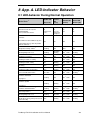
8 App. A. LED-Indicator Behavior
8.1 LED-behavior During Normal Operation
READY LED
ACTIVITY
(Green left)
LED
(Green)
LED-test.
The LEDs are turned ON in sequence
ON
Power-On Self-Test
Starts in parallel with the LED-test .
CLEAN LED
(Amber)
FAULT LED
(Amber right)
ON
ON
ON
Flashing in about
12 sec
After 12 sec:
Flashing during
cartridge load
OFF
OFF
ON
ON
ON
ON
Flashing
OFF
OFF
OFF
Aborting Diagnostic Test
Flashing
ON / OFF /
Flashing
ON / OFF
Cartridge not loaded.
OFF
OFF
ON / OFF
Cartridge loaded, no activity
ON
OFF
ON / OFF
Cartridge loaded, activity
ON
Flashing
Cleaning
OFF
Cartridge loading or unloading
Unrecoverable drive failure
Drive State 1
LED-test.
The LEDs are turned ON one-by-one.
Power-On Self-Test starts in parallel
2
with the LED-test .
Diagnostic Activity / POST
4
3
Flashing
3
OFF
3
OFF
ON / OFF
3
OFF
Flashing
ON
OFF
OFF
Flashing
ON / OFF
ON / OFF
OFF
ON / OFF
Flashing
OFF
ON / OFF
Flashing
Flashing
ON / OFF
Flashing
Flashing
ON / OFF
OFF
OFF
ON / OFF
Aborting Diagnostic Test
Flashing
ON / OFF
ON / OFF
Media Error (wrong, write protected or
harmed media)
OFF
Flashing
ON / OFF
3
OFF
3
Flashing
3
OFF
3
OFF
3
Flashing
3
ON
3
Flashing
3
Flashing
5
Firmware download
in progress
Firmware update
in progress
Firmware download failure
Over temperature
6
7
Tandberg LTO HH Installation and User Manual
5
35
Tandberg Data
LED Bahavious
NOTE 1:
Some of the states are difficult to see due to short duration.
NOTE 2:
LEDs are also used to indicate fatal errors at an early power-up stage. This is accomplished by turning the LEDs
ON one-by-one:
•
The Ready LED as early as possible (after CPU-initialization).
•
The Activity LED before initialization of serial communication interface (DACI).
•
The Clean LED after PROM checksum test.
•
The Fault LED after the CPU and SRAM Tests
After all LEDs are lit there is no controlled stop, and if the next LED-phase (flashing Ready LED) never
appears, the system has crashed somewhere in the remaining part of the POST/PUI Part1. All LEDs are steady
on for approximately 2 seconds.
NOTE 3:
•
The Clean LED steady ON indicates that a head cleaning operation is recommended (the Drive is still fully
operational with this LED steady ON) the LED is triggered after 100 hours of tape running time has elapsed,
if the Media Management Algorithm has detected severely degraded write performance, or if a hard
read/write error has occurred. The LED is not turned off by a power cycle. The LED is reset when cleaning
has completed successfully. The Clean LED is also turned on during Head Brush operaion (no sticky).
NOTE 4:
•
When a diagnostic activity leads to media operations (load/eject, read/write etc.) the LED behavior changes
to a behaviour that corresponds to this kind of operation in a normal activity, but with Ready LED still
flashing.
NOTE 5:
•
The Fault LED will flash to indicate an unrecoverable error. An unrecoverable error is an error condition that
results in the drive not being able to function unless initiator, operator, or service intervention is applied. An
unrecoverable drive failure is usually the result of a hardware error condition. One of the following actions
will be needed to clear the flashing Fault LED:
• Hard SCSI Reset
• Cartridge Emergency Eject
• Power Cycle
• Retry Firmware Download
An unrecoverable cartridge (media) failure is usually the result of a defective cartridge, media, or cartridge tate
and will require the drive to eject the cartridge (if possible) to clear the flashing LED.
NOTE 6:
•
Firmware download failed and the drive is not functional. The drive boot code is in control and the firmware
download should be retried. The drive can be identified via an INQUIRY command and is thereby bootable
while in this state.
NOTE 7:
•
The Fault LED will be on solid to indicate an over temperature (tape temperature > 47°C). If a tape is present
it will be ejected. The LED will remain on until one of the following conditions are met:
• The drive temperature goes below the preset maximum, and a new data or leaning cartridge is inserted
• The drive temperature goes below the preset maximum, and the tape drive is power cycled.
36
Tandberg LTO HH Installation and User Manual