1
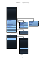
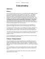
VX Flat Panel Display
Draft User Manual
Vutrix - Copyright © 2004
D R A F T - Subject to change
Contents
Introduction ......................................................................................................1
Setup ...............................................................................................................2
Menu Details ....................................................................................................4
Main Menu ...................................................................................................4
Signal Source........................................................................................4
Source Active ........................................................................................4
Scan Mode ............................................................................................6
Brightness, Contrast, Saturation, Hue...................................................6
Backlight................................................................................................7
Colour Temperature ..............................................................................7
Gamma .................................................................................................7
Sharpness .............................................................................................7
SDI Volume ...........................................................................................7
Adjustements Sub-Menu .......................................................................8
DVI-I Settings Sub-Menu.......................................................................8
Signal Banner........................................................................................8
Power-up State .....................................................................................9
Menu Size .............................................................................................9
Menu H Pos, Menu V Pos .....................................................................9
HD Refresh ...........................................................................................9
IR Control Setup Sub-menu ................................................................10
Code Version ......................................................................................10
Adjustments Menu......................................................................................11
H Size, V Size, H position, V Position .................................................11
DVI-I Setup Menu.......................................................................................12
Force Mode .........................................................................................12
Forced interface ..................................................................................12
Select Mode ........................................................................................12
Plug-n-Play..........................................................................................13
Phase ..................................................................................................13
Advanced Menu .........................................................................................15
Gage Options Sub-Menu.....................................................................15
Audio Channel A, B, C & D .................................................................15
Audio Meters .......................................................................................15
Audio Delay Enable.............................................................................15
Audio Delay Period .............................................................................16
Cross Hair Enable ...............................................................................16
Reformatted Output Enable.................................................................16
Reformatted Output Source ................................................................16
Cage Menu.................................................................................................17
Cage 1 / 2 Enable ...............................................................................17
Cage 1 / 2 Colour ................................................................................17
Cage 1 / 2 Left, Right, Top and Bottom...............................................17
Crop to Cage 1....................................................................................18
Crop 1 Colour......................................................................................18
ii
D R A F T - Subject to change
Menu shortcuts ..............................................................................................19
Description .................................................................................................19
Signal Source......................................................................................19
Sdi Volume..........................................................................................19
Aspect Ratio........................................................................................19
Brightness ...........................................................................................20
Contrast...............................................................................................20
Saturation (Colour)..............................................................................20
Backlight..............................................................................................20
Colourimetry ..................................................................................................21
Gamma ......................................................................................................21
History ....................................................................................................21
Colour Temperature ...................................................................................21
Guide to better viewing ..................................................................................23
Source signal ..........................................................................................23
Gamma...................................................................................................23
Backlight .................................................................................................23
iii
D R A F T - Subject to change
Introduction
The Vutrix VX range of displays are multi-input flat panel, colour displays with
interchangeable controllers allowing easy servicing, exchange and upgrade
options.
A fully loaded VX display has the following inputs available:
•
•
•
•
•
•
•
DVI-I (Analogue and Digital)
SDI (Standard Definition + Optional Hi-Definition)
Composite Video
S-Video
Red, Green, Blue and Sync / Y, Pb, Pr, and Sync
Infra-Red Receiver
Buttons
The following outputs are available:
•
•
•
•
Line audio (de-embedded SDI)
Speaker drive (de-embedded SDI)
SDI loop-through
Reformatted SDI (Standard definition model only)
1
D R A F T - Subject to change
Setup
All Vutrix displays have an on-screen menu that is designed to be easy and
intuitive to use. All options can be selected from the menus using just five
buttons on the front of the unit or via the remote control handset.
Rack mounted displays have buttons on the front for easy access.
Freestanding units are intended to be used with a remote control, so the
buttons are located out of sight on the bottom or rear of the unit, and should
only be required in emergencies, if the remote control is unavailable.
Figure 1 shows the general layout of the buttons on the display or the remote
control.
Figure 2 shows the main menu.
Fig. 1.
Fig. 2.
To activate the menu press the menu button.
To go back one menu or turn the menu off, press menu again.
When the menu is active, use the Up/Down buttons to move the highlighted
bar to the desired option.
Use the Inc/Dec button to change the value of the selected item.
The Inc button is also used to enter sub-menus. An arrow pointing to the right
instead of a value or slider indicates the item points to a sub menu.
If the menu has a “MORE” label at the bottom, this indicates that there are
more items in the menu. Continue moving down and the items will scroll up,
revealing more items.
Figure 3 shows the standard menu structure.
2
D R A F T - Subject to change
Main Menu
Signal Source
Source Active
Aspect Ratio
Scan Mode
Brightness
Contrast
Saturation
Hue
Backlight
Col Temperature
Gamma
Sharpness
SDI Volume
Adjustments
DVI-I Settings
Signal Banner
Power-up State
Menu Size
Menu H Pos
Menu V Pos
HD Refresh
IR Control Setup
Advanced
Code Version
Advanced Menu
Cage Options
Audio Ch A
Audio Ch B
Audio Ch C
Audio Ch D
Aud Meters A+B
Aud Meters C+D
Aud Delay Enable
Aud Delay Period
Cross Hair
Reform Output
Output Source
DVI-I Setup Menu
Force Mode
Forced I/F
Select Mode
Plug-n-Play
Phase
IR Setup Menu
IR Code
Accept
Cage Menu
Cage 1 Enable
Cage 1 Colour
Cage 1 Left
Cage 1 Right
Cage 1 Top
Cage 1 Bottom
Cage 2 Enable
Cage 2 Colour
Cage 2 Left
Cage 2 Right
Cage 2 Top
Cage 2 Bottom
Crop Cage 1
Crop 1 Colour
Fig. 3.
3
Adjustments
H Position
V Position
H Size
V Size
D R A F T - Subject to change
Menu Details
The following section details the individual menu options and shows an
example of how each appears in the menu.
Main Menu
Signal Source
This option cycles through the available inputs signals. A Fully built unit has
the following options:
Name
SDI
CVBS
SVIDEO
RGBS
YPBPR
PC_RGB
Description
SDI or HD SDI
Composite Video
Super-Video
Red, Green, Blue and Sync (or Composite Sync)
Component Video and Sync (or Composite Sync)
DVI or Analogue PC graphics
• SDI - Standard definition
The unit will automatically detect NTSC or PAL signals,
• SDI – Hi-Definition
The unit will automatically distinguish between SDI and HD-SDI and detect
the resolution and refresh rate.
• PC_RGB
The init will automatically detect digital or analogue signals. If both are
present, the digital signal will be selected.
The unit will automatically detect resolutions and refresh rates conforming to
VESA legacy or GTF timings. There are options to override this detection,
which are explained under the “Advanced PC” options.
Source Active
This item allows the user to tag each input as active or inactive. This is useful
when cycling through the inputs using shortcut buttons. Shortcuts are
explained in the next section.
4
D R A F T - Subject to change
Aspect Ratio
This represents the relationship between the horizontal and vertical size of an
image. There are three main settings:
•
•
•
4:3
15:9
16:9
Most LCD panels in the wide-screen format are in fact 15:9 and not 16:9 as
most people assume. Therefore a 15:9 option to allow the full display area to
be used.
The shape of the image on the display will depend on the native aspect ratio
of the display. The following tables show the relationship between native
display and selected aspects.
In the following tables, Pillar Box means that a black border is show on the left
and right of the image.
Letter Box means that a black border will be display above and below the
image.
4:3 Native Display Aspect Ratio
Selected Aspect Ratio
Result
4:3
Full Screen
15:9
Letter Box
16:9
Letter Box
15:9 Native Display Aspect Ratio
Selected Aspect Ratio
Result
4:3
Pillar Box
15:9
Full Screen
16:9
Letter Box
Selected Aspect Ratio
4:3
15:9
16:9
16:9 Native Display Aspect Ratio
Result
Pillar Box
Pillar Box
Full Screen
In addition to the above ratios, there are two further option:
•
•
625 1:1
525 1:1
These options allow 525 or 625 line, video images to be displayed without any
re-scaling. This can be useful when checking the quality of source signals
5
D R A F T - Subject to change
because it removes scaling artefacts generated by the display’s internal
scaler.
Scan Mode
This allows the user to select between:
•
•
Overscan
Underscan
Overscan represents a similar experience to viewing images on a CRT
television or monitor, whereby the video image is slightly larger than the
actual screen area. The result of which is that the user does not see part of
the outer edge of the image. This is the preferred viewing method for normal
television images since it hides various timing marks and imperfections in the
source signal. The amount of overscan is user adjustable via controls in the
“Adjustments” menu.
Underscan allows the user to see all areas of the picture. This is the
preferred viewing method for PC graphics images, but can also be used on
normal video images for verification.
Note: When set to Underscan, the “Adjustments” menu is disabled to
preserved true underscan mode.
Brightness, Contrast, Saturation, Hue
These options adjust the appearance of the picture to the users requirements.
The nominal values for these items are zero, i.e. the image is displayed
without any adjustment. Positive values increase the content of the selected
item, and negative values reduce the content.
NOTE: to adjust the overall brightness of the screen to match ambient lighting
conditions, it is recommended that the “Backlight” be adjusted first
6
D R A F T - Subject to change
Backlight
This option controls the intensity of the backlight and is primarily used to
adjust for ambient lighting. Reducing the backlight also reduces the amount
of power used by the display.
Note: this option is not available on plasma displays.
Colour Temperature
This alters the apparent colour temperature of the display. See the section
entitled “Colourimetry” for more details.
Gamma
This alters the apparent reverse gamma correction of the display. See the
section entitled “Colourimetry” for more details.
Sharpness
This option can be used to select a Hard or Soft picture. Soft pictures are
often used to hide noisy or grainy faults in the source signal. This option
should normally be left at zero.
SDI Volume
7
D R A F T - Subject to change
This option controls the volume of the de-embedded SDI audio from the
speaker outlet.
Adjustements Sub-Menu
This option points to sub-menus. Press the + button to enter the desired submenu. Details of these can be found later in this section.
DVI-I Settings Sub-Menu
This option points to sub-menus. Press the + button to enter the desired submenu. Details of these can be found later in this section.
Signal Banner
When this option is on, any changes in the detected signal will cause a
banner to appear in the corner, similar to the one shown below, indicating the
newly detected mode / format.
This banner also appears whenever the user exits from the menu system or
when the i button is pressed.
Note that the banner cannot be display while menus or shortcuts are active.
Example of banner information.
The top line of the banner indicates the interface receiving the signal
The second line indicates the format or resolution of the received signal.
The third line indicates whether the input is from a digital or analogue source.
8
D R A F T - Subject to change
Power-up State
This option defines what happens when power is applied to the display.
“On” will cause the display to show the image of the current input.
“Standby” will cause the unit to enter standby mode. It will then be necessary
the press the power or menu button the wake up the display.
In general, “Standby” should be used for domestic applications where the
display should not come on after a power-failure. “On” should be used in
commercial applications where the displays are used to show public
information at all times.
Menu Size
If the user finds in hard to read the menu, the user can select “Large” format
menus. These are easier to read but obscure more of the image while active.
Menu H Pos, Menu V Pos
These items allow the user to adjust the horizontal and vertical position of the
menu to a convenient location on the display.
HD Refresh
This item is used in conjunction with the optional HD interface. Options are:
•
Precise
9
D R A F T - Subject to change
•
Standard
“Precise” allows the display to distinguish between refresh rates at 23.98,
29.97, 59.94 and those at 24, 30 and 60. If the signal has poor jitter or loss,
then the display may have difficulty sensing the exact refresh rate. This may
cause the display to continually jump between two settings. If this occurs,
then set this option to “Standard”.
Note: The display will correctly lock its refresh rate to the input, regardless of
which setting is selected.
IR Control Setup Sub-menu
This sub-menu allows the user to configure options for the infra-red remote
control. Details appear later in this section.
Code Version
This item cannot be selected and is provided to show which version of
software is operating in the display.
10
D R A F T - Subject to change
Adjustments Menu
H Size, V Size, H position, V Position
These items allow the user to adjust the position and size of the image. The
nominal values are zero, i.e. the image is displayed at its theoretical optimum.
Increasing the “Size” values will cause more of the input image to be captured
and displayed which has the effect of reducing the size of details in the image.
Conversely, reducing the “Size” values will cause less of the input image to be
captured and displayed which has the effect of increasing the size of details in
the image.
Increasing the “ H Position” value will cause the active start point of each line
to be moved further to right. This has the effect of moving the visible image to
the left.
Increasing the “ V Position” value will cause the active start line of the image
to be moved further down. This has the effect of moving the visible image up.
The valid range for these settings varies according to numerous factors such
as resolution, timing, signal polarity etc. Therefore, caution should be taken
when adjusting these values. If the image becomes unstable or freezes, then
back off the value until a normal image returns.
11
D R A F T - Subject to change
DVI-I Setup Menu
All controls in this menu are associated with the DVI-I input connector
Force Mode
The display is designed to automatically detect any graphics mode
conforming to Vesa Lagacy or GTF timings. If the mode does not exactly
conform to these standards, the screen may fail to detect valid timings. In this
case, the user can override the automatic detection and force the display into
one of these known modes.
Note: if this option is not selected, then the following two options will be
disabled.
Forced interface
This option allows the user to select which pins to use as the input. The
available options are:
• Analogue
• Digital
If Analogue is selected, then the analogue RGBHV will be used.
If Digital is selected, then the digital DVI signals will be used.
Select Mode
This option allow the user to scroll through all of the supported graphics
modes. The format of the selection is:
• First number is horizontal active pixels
• Second number is vertical active lines
• Last number is the refresh rate
There are two sets of modes. The Vesa Lagacy modes are listed first. The
Vesa GTF modes are listed last, indicated by a “G” character on the end after
the refresh rate value.
12
D R A F T - Subject to change
Plug-n-Play
Options are:
•
•
Analogue
Digital
This option is required in situations where the hardware generating the
graphics uses Plug-and-Play to detect the display before it will output any
graphics (most PC’s require this). The display supports both Analogue and
Digital data on the same connector (DVI-I), but due to limitations in the Vesa
specification for automatic monitor detection, a display must announce to the
hardware that it is either analogue or digital, not both. This option allows the
user to decide which type of display the hardware will detect.
Note: Regardless of which option is selected, the display will automatically
use whichever signal it gets. If Analogue and digital are present at the same
time, then the digital data will be used.
Phase
This option is sometimes required when using the analogue input. If a slight
shimmering is seen at colour transitions, adjust this setting until the display
appears steady and sharp.
13
D R A F T - Subject to change
IR Code Menu
The Vutrix remote control handset is able to transmit codes with one of four
separate identification codes, called System Codes. This allows significant
flexibility to resolve potential conflict problems with other equipment. Such as:
•
•
•
Up to 4 Vutrix displays can be used in one single location using a
single remote control handset.
If the Vutrix codes interfere with other equipment.
Other equipment interferes with the Vutrix display.
The Vutrix remote control uses industry standard Philips RC5 codes.
The four buttons A, B, C and D near the top of the remote, are used to
configure the remote to use System Code values 0 to 3 respectively. If the
display is configured to respond to all codes, then the display will work
regardless of which button (A to D) is used. If the display is configured to
work only with one of the codes, then the appropriate button (A to D) must be
pressed prior to using the remote control with the display.
If codes from another manufacturers remote control (such as a Philips TV)
cause problems with the display, try changing the IR code setting in the menu
(see below)
IR Code
This option configures the display to react to a different System Code.
Options are:
• A
• B
• C
• D
• All
• None
See description above for more details.
Note: when changing this setting, the display will not use the new value until
the “Accept” option is used to confirm it (see next menu item). This is to
prevent the remote control from becoming inoperative while changing the
setting.
Accept
After making a change to the IR CODE option, select this option and use the
Inc or Dec button to activate the new setting. “ACCEPTED” will be displayed
momentarily, before returning to “NO”.
14
D R A F T - Subject to change
Advanced Menu
Gage Options Sub-Menu
This sub-menu allows the user to control the caging options.
Audio Channel A, B, C & D
These options select which audio channels to de-embed from the SDI signal.
Any channel from 1 to 16 can be selected for each of the 4 channels. The
channels selected for A and B will be used as the left and right outputs from
the Audio Line output and Speaker Drive output. All four channels can be
monitored using the Audio Meters detailed below.
Audio Meters
These options enable the overlaid audio meters. These can be used to
monitor the presence of embedded audio on the SDI input signal.
The meters can be enables in pairs, A+B and / or C+D.
Audio Delay Enable
This option enables the audio delay feature. This is used to delay the audio
with respect the video to correct lip sync caused by video processing in both
the display and in external equipment.
15
D R A F T - Subject to change
Audio Delay Period
T.B.A.
Cross Hair Enable
This option enable a cross in the centre of the screen, This can be useful for
broadcasters to show the centre of the screen.
Reformatted Output Enable
This enables the application of a cropped image on the reformatted SDI
output. The amount of the image that is cropped is defined by Cage 1. See
the Cage Menu options for more information.
Reformatted Output Source
This defines the source signal used to generate the reformatted output. The
options are
• Analogue
• SDI
The “Analogue” setting uses the current input from any of the analogue
connectors. To use this setting, one of the analogue inputs must be selected
as the source to the main display.
The “SDI” setting uses the SDI input as the source.
16
D R A F T - Subject to change
Cage Menu
Cage 1 / 2 Enable
These options switch on the relevant cage. This is a coloured rectangle
overlaid on the image and is useful for checking exact locations for areas in
the input signal.
Note: the Cage function is only available when analogue video or SDI is
selected and the main input.
Cage 1 / 2 Colour
These options allow the user to select the colour of the cage overlays. The
available colours are:
•
•
•
•
•
•
•
•
White
Yellow
Cyan
Green
Magenta
Red
Blue
Black
Cage 1 / 2 Left, Right, Top and Bottom
17
D R A F T - Subject to change
These options allow the user to set the position of the two cage rectangles.
The Left and Right coordinates are calibrated in pixel pairs giving a range 0 to
359. The Top and Bottom coordinates are calibrated in field lines giving a
range 1 to 288 for 625 video and 1 to 240 for 525 video.
There are two separate sets of values, one for 525 and one for 625 line video.
The values that appear in the menu are for whichever is currently being
detected. If the input changes from 525 to 625 or vice versa, the menu will
update the values to the newly detected video format.
Note: the Cage function is only available when analogue video or SDI is
selected as the main input.
Crop to Cage 1
This option enables cropping on the reformatted SDI output. The settings for
cage 1 are used to locate the crop.
Crop 1 Colour
This option sets the colour of the cropped area on the reformatted SDI output.
Available colours are:
•
•
•
•
•
•
•
•
White
Yellow
Cyan
Green
Magenta
Red
Blue
Black
Note: this option has no effect if Crop Cage 1 is disabled.
18
D R A F T - Subject to change
Menu shortcuts
Description
Some of the more frequently used menu items are available via shortcuts.
This enables the user to quickly change an item without navigating through
the menu structure.
Shortcuts are only available when the menus are not active. For more details
about the function of the shortcuts see the relevant menu option in the
previous section.
When a shortcut is activated, it remains visible until no buttons are pressed for
several seconds, at which point it will automatically disappear
Signal Source
The up / down (P+ / P-) buttons are used to cycle through the active inputs.
Also the AV button can be used to cycle to the next active source.
To set an input as active, enter the main menu, select the source via the
“Signal Source” option and then select “Yes” via the “Source Active” option.
Exit from the menus and the use the up/down buttons the select the required
source via shortcuts.
Sdi Volume
Use the inc / dec (Vol+ / Vol-) buttons to change the volume of the deembedded SDI audio.
Aspect Ratio
19
D R A F T - Subject to change
Each time this button is pressed, the display cycles to the next aspect ratio.
Brightness
This button enables the Brightness shortcut. Use the Inc / Dec buttons to
change the setting.
Contrast
This button enables the Contrast shortcut. Use the Inc / Dec buttons to
change the setting.
Saturation (Colour)
This button enables the Saturation / Colour shortcut. Use the Inc / Dec
buttons to change the setting.
Backlight
This button enables the Backlight shortcut. Use the Inc / Dec buttons to
change the setting.
20
D R A F T - Subject to change
Colourimetry
Gamma
History
Until recently, the only practical way to view electronic video images has been
via a television or monitor using a cathode ray tube (CRT). The image is
produces by exiting special phosphors on the inside of the screen with a
beam of electrons. Unfortunately the intensity of the light emitted by the
phosphor is not linear with respect to the energy in the electron beam. This
problem could have been resolved by adding electronics within the display to
compensate for this non-linear characteristic (called gamma). This would
have significantly increased the cost of displays, especially in the early days.
It was therefore decided to apply gamma to the video within the camera.
When this video is then played back on a CRT, the result is a linier response.
Gamma has been applied to all video ever since.
Many new display technologies emerging today do not use phosphor to
generate the image and therefore do not naturally display video correctly.
TFT panels such as those used in Vutrix displays do not have a gamma or a
linear response. It is therefore necessary to remove the gamma (called
reverse gamma) and then apply a new correction specific to the panel type.
The result of this technology is to allow the display to simulate the response of
a CRT in order to correctly reproduce the video as though it where being
viewed on a CRT.
All Vutrix displays have a gamma control to allow the user to select the best
gamma to match the source material
Colour Temperature
Colour temperature is an industry standard way to describe how white an
image is compared with daylight. This can be likened to viewing a piece of
paper under candle light or under fluorescent lighting. The paper is always
the same colour, but the ambient lighting in which it is viewed makes it appear
different.
Colour temperature is a colour scale representing the colour of light emitted
from a piece of platinum at specific temperatures in the Kelvin temperature
scale.
As it is heated it will initially appear red, then through yellow, yellow white,
right through to blue white.
21
D R A F T - Subject to change
All Vutrix displays have a colour temperature control to compensate for the
ambient lighting conditions in which the display is situated. As a rough guide
the following settings are recommended:
•
•
•
5400: Low level incandescent lighting or candlelight
7200: Fluorescent lighting
9200: Daylight
22
D R A F T - Subject to change
Guide to better viewing
This section is a quick guide to getting the best viewing experience from your
Vutrix display.
Source signal
The display has a selection of different inputs. The best quality inputs should
be used whenever possible. The following list shows the recommended
inputs starting with the best.
•
•
•
•
SDI or HD SDI
RGB or YPbPr
SVideo
Composite
Gamma
For video sources a reverse gamma of around 2.22 is recommended
For DVI-I sources, many PC’s have options for applying gamma, so if gamma
is applied at the PC, select the equivalent the reverse gamma on the display.
e.g. if the PC applies a gamma of 0.45 then the display should be set to:
1
0.45
which is 2.22.
Backlight
Adjust the backlight low for low ambient lighting conditions and high for bright
ambient lighting conditions. This should be done before making any
adjustments to the brightness or contrast controls.
23