1
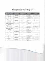
LPRDS-CMS 201 1 Lafayette Photovoltaic Research and Development System: Cell Management System ECE 492 - 2011 Acceptance Test Plan Created by Erik Adolfsson
Last Revision 04/20/11 by Greg Earle
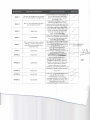
Requirement
Applicable/Modification
Confirmation Method
R002-2
We are developing a new design
for per-cell battery management.
Demonstration of convergence of
a 4-cell pack as per Test TOOl
which will run ten (10) charge/
discharge cycles
R002-3
We are only charging one pack,
not the entire system.
R002-4
Applicable
R002-S
Applicable
R002-6
12C is used to monitor in detail
voltage, current, and SOC of
battery pack, including every
individual cell.
R002-8
GPR001-1
Applicable
Applicable
Using resistive bypass, over ten
(10) charge/discharge cycles,
measurement of voltages and SOC
via Simulink will demonstrate per
cell balancing as per Test TOO l
Using Simulink, a discharge curve
will be created to demonstrate
that over-discharge does not
occur as per Test TOOl
Visual demonstration of OBPP will
confirm operational "stand-alone"
state via LED indicators during
Test TOOl & Test T002
12C interface will be utilized during
Test T002 to monitor the voltage,
current6erat~nd SOC of
each individual cell in the pack via
a PC terminal application
Final Report will include
photographic evidence of usage of
existing LiFeP04 cells
/
/
I
(/tVC4U"'r24TEZ>
:fvT w~(2..t'.5
V
Sec L
It ILOpa tf lISt 6f /...- /
documentation iUhilU61Wil5
~=~~1C~iS
localt!u UII LtTe'jJrOject website.
Another member of the team will
edit each individual's work to
ensure adherence to group
standards, compliant with those of
Lafayette College writing courses.
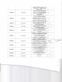
GPROOl-2
Applicable
GPROOl-3
Applicable
Inspection
GPROOl-4
Applicable
Inspection of QA Audit Report and
low-level test reports
Applicable
All schematics, mechanical
draWings, circuit net-lists, BOMs,
artwork, assembly drawings and
other files necessary for
manufacturing are located on the
GPR001-S
Achieved
r
./
~-_
;"'>..ft
L
f rt q{Jl
11.
'/.0-
;L firiL
Cf1-tL- w
GPROOl-6
Applicable
GPROOl-7
Applicable
GPROOl-8
Applicable
GPROOl-9
Applicable
GPROOI-IO
Applicable
GPROO2-1
Applicable
GPROO3-1
Applicable
GPROO4-1
Applicable
GPROO4-2
Applicable
GPROO4-3
Applicable
GPROO5-1
Applicable
Project Website under the tab "Resources" -> "OBPP Design Documents" All datasheets of components used in the system design are located on the project website
under the tab "Resources" -> " Datasheets" The final report will include a section entitled Firmware Development which will include
documentation of the design
decisions, implementation and
issues with the current firmware
See User's Manual located on
Project Website under the tab
" Project Documents"
See Maintenance Manual on
Project Website under the tab
"Project Documents" Inspection of Project Website. All files to be delivered are in standard and portable docu ment formats . SWROOl-1: Environmental Memo (in the Final Report) will analyze that the syste m meets the
operational and storage
temperatures. In addit ion, RoHS
compliance will be analyzed .
SWROOl-2: EMI/EMC Memo (in
the Final Report) will analyze the
unintentional electromagnetic
radiation concerns of the system
Environmental Memo will analyze
if the system has any hazardous
materials and if they comply with
LC Chemical Hygiene Plan
Environmental Memo will make
sure all materials used in
electronic circuit fabrication are
RoHS compli ant
Environmental M emo will
consider disposal of design or
prototypes
Inspection
~
/
V
/
V
/
K
/
V
~
~
Firmware will be peer reviewed to
ensure that it complies with all
principles and practices
established in LCs course CS205
Archived revision histories (zip
files) and final version of PIC
firmware will be located on the
project website under
"Resources" -> "PIC Firmware"
tab. Testing software (Simulink
files) for ATP/ATR will be located
on the project website under
"Resources" -> "Test Software"
tab. A Software Readme file will
be located on the project website
under the "Resources" tab.
Ajumperconnection on the board
(Ref Des) will reset the board
when the contacts are bridged .
/
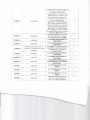
GPROOS-2
Applicable
GPROOS-4
Applicable
GPROOS-S
Applicable
See Voltage Analysis Memo in
Final Report
GPROOS-6
Applicable
See Power Dissipation Memo in
Final Report
../
Test TOOl demonstrates that the
components used do not have a
surface temp> 70·C above
ambient (30·C)
V
Su rface tem peratu re rise no
GPROOS-8
greater than 70 degrees C above
ambient
v/'
V
GPROOS-9
Applicable
See Power Dissipation Memo in
Final Report
/'
GPROOS-10
Applicable
See Voltage Analysis Memo in
Final Report
~
GPROOS-ll
Applicable
See Maintenance Manual on
Project Website under "Project
Documents"
V
GPR006-1
Applicable
See Reliability Memo in Final
Report
V
GPR006-2
Applicable
See Reliability Memo in Final
Report
/
GPR006-3
Applicable
See Reli ability Memo in Final
Report
Applicable
Tests TOOl will be conducted
within a 24-hour period of
continuous system operation .
V
V
GPR006-4
GPR006-S
Applicable
See Reliabi lity Memo in Final
Report
GPR007-1
Applicable
See M aintainability M emo in
Final Report
GPR007-2
Applicable
See M aintainability Memo in
Final Report
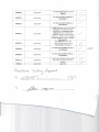
See ATP for spare parts list, User's
Manual for troubleshooting
procedures, and Maintenance
Manual for more elaborate
diagnosis and troubleshooting
resources. All docs are located on
Project Website under "Project
Documents"
Test T003 will check the
usefulness of the User and
Maintenance Manuals
GPR007-3
Applicable
GPR007-4
Applicable
GPR008-1
Applicable
See Manufacturability Mem o in
Final IReport
GPR008-2
Applicable
See Manufacturability M emo in
Final Report
GPROll-l
Applicable
Final Project demonstration will
take place on 5/6/11 for ECE
Faculty
GPR012
Applicable
Inspection
ACC~f1Ct'lC!.e f.e5-kYlJ Ap(I)v-tJ X~-'-
V
V'
V'
/
vi
v'
V
</
/
Acceptance Test Report 0001: CDR
Materials
0002: User's
Manual
--
~3-J
3/2/2011
~
5/6/2011
I
I
~~ It
0003: Final
Report and
Maintenance
Manual
5/6/2011
£0
I[
0004: Acceptance
Test Plan
4/15/2011
~~
,
0005: Acceptance
Test Report
5/3/2011
0 006: QA Audit
Report
5/3/2011
0007: Project
Website
0 008 : LPROS
CMS-2011
Integrated
0 009 : Conference
Paper
0010: Project
Poster
Periodically
{
t/
Sf£;
I[
~
c./
:£;0
11
5/6/2011
:D~ II
4/8/2011
§j~ { I
5/6/2011
V
SJJz-; I/
Introduction
In order to ensure the project can meet the requirements of the LPRDS-CMS-2011 Statement of
Work, it must successfully pass acceptance testing. These tests will verify the various functions of the
cell management system (CMS). The Acceptance Test Plan (ATP) gives step-by-step instructions on how
to test the system to the fullest extent and make sure the CMS meets all the system req uirements.
System Requirements
The project was originally presented with over 80 requirements. These were reviewed and
several were not achievable/ applicable within the scope of the ECE 492 14-week term. The following
are the agreed upon and altered requirements adapted from the LPRDS-CMS-2011 statement of work.
R002: Energy Storage
2. The existing ESS design does not allow any automated per-cell or aggregate battery management. There is
no way to charge the cells individually taking into account their individual characteristics. The LPRD5-CM5
2011 shall re eRfjiReer design the E55 to permit per-cell battery management.
3. The new system shall charge every cell in the ESS in the 4-cell pack to its maximum recommended
capacity. Should some cells charge faster than others, a means shall be provided to bypass the cells that
become full first, allowing complete charge to be delivered to cells that charge more slowly.
4. On discharge, every cell shall be monitored and over-discharge of any individual cell must be avoided.
5. The ESS shall be capable of standalone operation. It shall be possible to properly charge and discharge the
ESS without needing an outside computer system for control or monitoring. Indicators shall be provided
that give a basic display operat ional state (charge/discharge rate) and charge state (fuel gauge). Controls
shall be provided, if needed, to permit standalone management.
8. In addition to local controls and indicators, a remote ~ IIC system shall be able to monitor in detail
the voltage, and current of, and state of charge of the aggregate !iSS batter.,. and every individual cell in
the CMS fSS, as well as the overall state of charge of the pack !iSS paraFfleters
9. Although a new charge-management system must be developed, the LPRDS-CMS-2011shall re-use the
existing LiFeP04 cells incorporated in the existing ESS system . Also, to the largest extent possible, the
existing mechanical enclosure, cabling, controls, and safety interfaces for the old ESS should be re-used.
GPR001: Documentation
1. Complete and accurate documentation must be provided with all projects. These documents shall include
documents for mechanical and electrical fabrication, test results, software development kits,
maintenance manual, user manual , and specification compliance matrices, and technical papers. All
documentation shall be accumulated in electronic form, centralized in a project web site, and thoroughly
indexed. The web site represents the primary point of delivery for document data items.
2. Text documents shall be written in a professional style commensurate with quality standards established
by Lafayette College ECE writing courses (e .g. ES225 and ECE211).
3. All original paper documents should be scanned and stored electronically. The original should be disposed
of per GPR012.
4. Test reports for hardware and software must show the date/time of testing, name and signature of the
tester, and name/signature of any witnesses.
5. For all electronic PCB designs the following fabrication documents are required: dated, and numbered
schematics or mechanical drawings on Lafayette College drawing format, circuit net-lists, bi lls of materials,
artwork, assembly drawings, and all other files and instructions necessary for CAM or manual
manufacturing. The source files for fabricating PCBs and editing linked schematics shall be clearly
identified and preserved.
6. Documentation must be provided both for original designs and for any subcontracted designs. For
purchased vendor components within the design, all vendor manuals and documentation shall be
retained with the system. Proper mechanical drawings are required for fabricated mechanical parts.
Manufacturers data sheets and interface drawings are required for all purchased components.
7. For software and firmware designs: Source code, and executable binaries for all applications; Veri log,
constraints and configuration bitstreams for FPGAs; and ROM image fi,les in commonly accepted J'ED or
H'EX formats for all PLDs.
8. A "Users" manual is required. This should be a high level document that explains al'l operational
procedures and techniques needed to operate the system is a safe and effective manner, including
"getting started", "FAQ", detailed explanations of all functions and controls, and user level calibration and
maintenance.
9. A technical "Maintenance" manual is requ ired. This should be a low level document that explains the
unique technical principles and details of system operation. The maintenance manual iflcludes
information on any advanced maintenance or calibration techniques that could be applied by an expert
maintainer. A set of schematics, pinouts of all connectors, the signal assignmen,ts of all cables, and the
semantics of all interfaces (hardware and software) must be documented within this manual,
10. All documentation must be provided and delivered in electronic form. 'Emailing a description of a
document along with a URL into the project web site is an acceptable and desirable form of delivery. The
use of standard and portable document formats (e.g. PDF, TXT), must be used so that the documentation
can be viewed on any computer without the need for proprietary applkations. The documentation must
be arranged in an organized and professional manner on the project web site.
GPR002: Environmental
1. All projects must demonstrate reliable and normal functional operation in ambient lab temperatures of
15°C to 30 °C, 10% to 80% RH, non-condensing. The overall system must tolerate a storage environment
of 0 °C to +60 °C, 5% to 95 % RH, non-condensing. Designs should use electronic components rated for
commercial temperature range (0 -70 "C) or better.
GPR003: EMljEMe
1. Unintentional electromagnetic radiation radiated or conducted from designs must meet US CFR Title 47
Part 15 subpart B regulations for Class A digital equipment. Intentional radiators must meet subpart C
regulations. Exemptions from 15.103 are not allowed .
GPR004: Hazmats
1. Hazardous materials should be avoided in designs. If use of a hazardous material is essential to the
function of the design and there is no non-hazardous alternative, the use of the hazardous material must
comply with the Lafayette College Chemical Hygiene Plan .
2. All materials used in electronic circuit fabrication must meet 2002/95/EC RoHS directives. NiCd or Lead
Acid batteries may not be used in new designs.
3. Any portion of the design or prototype that is discarded mu st be discarded according to the Lafayette
College Chemical Hygiene plan . Also, projects should discard the collected electronic waste in an
ecological -friendly manner as per the 2002/96/EC WEEE directive, ei.ther by ecological disposal or by
reuse/refurbishment of the collected waste.
GPR005: Safety and Good Practice
1. All work shall comply with good industry practice that enhances reliability and maintainability. These
practices include such items as
•
Color coded wiring in accordance with applicable industry standard color codes(e.g. NFPA 79 or
UL508 for power wiring, EIA/TIA 568 for network wiring, etc ... )
•
Clear labeling of all controls and indicators.
•
An obvious and clearly labeled system-wide power shutdown switch.
•
Silkscreen on PCBs that includes reference designators, noted power supply voltages and other
critical signals. Silkscreen must show a Lafayette College logo, the words " Made in USA", a RoHS
logo, assembly number and revision, and designated locations for serial numbers to be attached
or written. PCB bottom copper should have text indicating the board part number and rev.
•
Fuses shall be socketed and at least 5 spares must be included with system delivery; breakers
shall be resettable. All are readily accessible per maintainability requirements.
•
Service loops on all cable harnesses.
•
Acces s panels on enclosures.
2. Software/firmware developed mu st adhere to the principles and practice established in Lafayette College
course CS205. Source code must be maintained under configuration control.
4. Embedded computer processors shall have reset buttons. These buttons must be readil,y acceptable for
maintenance, but not so easy to hit that they degrade reliability.
5. Current drain analysis must be provided for all power supplies. Each supply voltage must have a current
rating with a 50% safety factor over the anticipated peak current.
6. All re sistors or other parts dissipating more than 25 milliwatts shall be identified and analysis shall be
provided that shows all such parts are properly rated for peak and average power dissipation and have a
proper heat sink and fan, if necessary, that provides adequate cooling over the ambient temperature
range.
8. Components must be cooled such that the surface temperature is no greater than 4G- 70 degrees C above
ambient.
9. Power dissipation rating of parts shall be 50% overrated over the required temperature range.
10. Working voltage of capacito rs shall be 25% overrated above the peak voltage anticipated, including all
expected glitches, spikes, and tolerance limits.
11. Project activities must adhere to the general Lafayette College safety policy, possibly augmented by any
ECE Department or ECE Laboratory safety rules. Applicable rules are those in effect on the date of ATP.
GPR006: Reliability
1. The system wide Mean Time Between Failures (MTBF) must be greater than 1000 hours over the system lifetime. 2. Reliability requirements must be demonstrated in the ATP both by analysis and by Inspection . The use of
MIL-HDBK-217, Bellcore TR-332, or other equivalent technliques are encouraged for the analysis. Every
part and subsystem in the full BOM must be explicitly con si dered in the MTBF analysis .
3. Parts with power dissipation over 25 mill iwatts shall be identified and the reliability analysis shall include
reliability derating of the se components based on the expected dissipation .
4. In addition to the analysis, a reliability inspection shall be conducted during ATP where t he system is
shown to operate for 24 hours without any obvious failure.
5. Failures are defined as anything that causes system requirements to be missed . Failures include, but are
not limited to computer software lock-ups, shutdowns caused by overheating, automatic operations
stalled by exceptions or requests for human intervention, as well as random component failure.
GPR007: Maintainability
1. The system wide Mean Time To Repair (MTTR) must be less than 1 week over the system lifetime.
2. Maintainability requirements must be demonstrated in the ATP both by analysis and by Inspection . The
use of MIL-HDBK-472 (Nl) and MIL-STD-470B, ISO/IEC 25000:2005, or other equivalent techniques are
encouraged for the analysis .
3. In the maintainability analysis you should assume a stock of recommended spare parts . The list of these
spare parts should be included in the ATP. The Users Manual should include a section giving simple
troubleshooting procedures. The Maintenance Manual should have more elaborate diagnosis and
troubleshooting resources.
4. In addition, a maintainability inspection shall be conducted during ATP w here a novice using procedures
included in the User Manual demonstrates the diagnosis and repair of a li kely failure, and an expert
using resources included in the Maintenance Manual demonstrates the diagnosis and repai r of an UN
likely failure.
GPR008: Manufacturability
1. A production design is a project design that could reasonably be manufactured in large quantity (e.g.
greater than 1000 units/yr) . All production designs mu st be built from components and subassemblies
that have a sustainable source of supply over the system lifetime. To demonstrate that this requirement is
met, it must be shown that each item in the Bill of Materials (BOM) for the design is available from a
minimum of two independent suppliers. In addition, industry trends shall be considered when selecting
24 implementation options. Designs should choose options most aligned with future industry trends.
2. The tolerances of components shall be considered in the design. Any component with a value that
determines a critical voltage, time constant, frequency, or other parameter shall have a tolerance such
that system requirements are met with 99% yield in manufacturing. An analysis shall be provided that
identifies any tolerance critical components and proves that the tolerances are adequate to meet system
requirements at that yield .
GPROll: Project Demonstration
1. Comp leted projects mu st be demonstrated for review by ECE faculty.
GPR012: Final Disposal o/Projects
1. Projects may be stored for future work, placed on display, or discarded. Time must be included in project
schedules for final disposal.
2. If a project is to be stored, all its materials must be collected together in a single location. If possible,
these materials should be enclosed in a sealed container, locked cabinet, or secure room that contains
only these materials from one project and no other. .If certain parts are impractical to store with the bulk
of the project materials, these separate parts must be clearly labeled so their association with the stored
project is obvious. Projects placed on display may have portions r.ot on display. The undisp layed portions
shall be either stored or discarded as described herein.
3. Portions of projects or complete projects that are discarded must be discarded in accordance with Hazmat
procedures described herein.
4. Test equipment moved from labs shall be replaced in its original location .
5. Trash, loose wires, scattered components, and other detritus resulting from frenzied development and
testing shall be cleaned up.
6. Paper documents that have been scanned per GPROOl shall be placed in a paper recycling bin .
7. The project web site must be updated with all final documents. The documents on the final web site must
match the delivered system. Obsolete documents on the web site shall be removed.
In addition, the following special waivers and restrictions are applicable to the project:
Special Waivers and Restrictions (SWROOl)
1. Analysis must show the system is compliant to GPR002; however, no formal environmental testing or
empirical data is required.
2. Analysis can be used to show the system is compliant to GPR003; no formal EMI/EMC certification testing
or empirical data is required .
3. Surface temperature s, supply current drains per GPR005 must be analytically predicted at CDR and
physically measured and verified as compliant during ATP .
6. The system life for the purpose of requirements analysis other than for GPR009 shall be 5 years.
The first requirement of the LPRDS-CMS-2011 is to develop a new Energy Storage Subsystem
(ESS) to replace the existing ESS. The main function of the ESS is to act as an Energy Accumulator t o
store the excess electrical energy available from the PC array and later deliver that stored energy to the
Energy Delivery Subsystem (R002-1) . The scope of this project is limited to a cell balancing PCB that is
attached to each 4-cell pack. The system is scalable and can be used within the current ESS but will not
be implemented or tested at this time. For this system, the SCADA interface is not used (R002-7).
Instead an
2
1
C interface, which uses a USB adapter to communicate wi,th a Pc. Since we are reducing the
scope of our project we cannot conform to ESS requirements inherited from previous years (R002-9,
R002b-l through R002b-13). Our project is not sophisticated enough for us to write a software
application for interfacing with the pack (R006-1, R006-2). We also cannot write a demonstration
application on such a simple circuit (R008-1 through R008-S), however the OBPP board does
demonstrate operation through the implementation of 4 LEOs demonstrating bypass and 3 LEDs
indicating charging, discharging, and board status. We are not interfacing with any high voltage or
photovoltaics (R009-1 through R009-3, R010-1, R010-2, SWROOl-4, SWR001-S). In order to provide the
ability to interface with the previous LPROS system, the current system does include optical isolation for
high voltage protection. We are not reusing previous year's safety interface (ROll-1), but the redundant
temperature safety system (RTSS) developed in this year's system is compatible with the safety loop
developed by previous LPROS projects. An electrical safety plan was written by previous LPROS teams
and adopted within the first week of the project (SWROOl-7). We are not developing a DC potential
difference greater than 30 Volts . A 4-cell battery pack produces around 12 Volts (GPROOS-12). We are
not designing our communication cables, power harnesses, or connectors according to NEC ANSI/NFPA
70 and ANSI C-2 (GPROOS-13). We are not interfacing with the Lafayette college power grid (GPROOS-14).
We are not using lasers or any RF in our design (GPROOS-1S, GPROOS-16). While the CMS will not operate
by continually balancing a pack of cells for ECE department visitors, a demo program will be developed
to show that the board design and integration on a pack of four cells produces a meaningful response
from the firmware programmed onto the PIC microcontroller (GPROll-2).
Acceptance Test TOOl:
This test verifies the following requirements:
R002-2: The LPRDS-CMS-2011 shall re engineer the design a new ESS to permit per-cell battery
management
R002-3: The new system shall charge every cell in the E:SS in the 4-cell pack to its maximum
recommended capacity. Should some cells charge faster than others, a means shall be
provided to bypass the cells that become full first, allowing complete charge to be
delivered to cells that charge more slowly.
R002-4: On discharge, every cell shall be monitored and over-discharge of any individual cell
must be avoided
R002-S: The ESS shall be capable of standalone operation. It shall be possible to properly charge
and discharge the ESS without needing an outside computer system for control or
monitoring. Indicators shall be provided that give a basic display operational state
(charge/discharge rate) and charge state (fuel gauge). Controls shall be provided, if
needed, to permit standalone management.
SWROOl-3: Surface temperatures, supply current drains per GPROOS must be analytically
D
predicted at CDR and physically measured (less than 70 C over ambient (30 DC) ) and
verified as compliant during ATP.
GPROOS-8: Components must be cooled such that the surface temperature is no greater than
40degrees C above ambient.
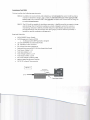
Required Materials:
•
MPJA 9604PS Power Supply
•
Cell Management System (CMS)
o
4-cell pack with OBPP (partially charged)
• (2) Gold SDP4040D DC Solid State Relay
• (4) 120 Watt i-Ohm resistors
Thermometer
•• IR"'''-bho
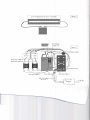
\ 1he.('Mo ,v\oC.ftr • PC running Simulink • National Instruments BNC2110 Data Acquisition Board
• Test Power Cables 1,2,3
• Test Data Cables 1,2,3 • Test Voltage Cables 1,2,3,4 • - Tszl g,l'
C
I.!t1fJ~
I; , ; I
r---------------------------------------------
I
Figure 1 I
I
I
I
I
2S-2P Configuration (2 serial- 2 parallel)
I
I
I
I
I
I
----------- - -------------- -- - - --------------~
Test Voltage
Cables 1-4
Figure 2
Test Power Cable
Test Power Cable ~_...L---I---t--..,
i 3 of Data Connector
Test Data Cable 3
Test Data Cable 2 \'<: <.. nO< <-1>'" _
'1>0 CV'd
\
Test Data Cable 1 ,c;.-l
~'-''-___
-;-2c. .... 'PI!.
~
_ _:---"_ V0\~ Test Procedure:
• Take 4 LiFeP04 cells and fully charge them individually using MPJA 9604PS Power Supply until
each cell voltage reaches 3.8 V
one. ::LQ..
• Discharge all the cells to the following SOCs: 80%, 50%, 25%, 10% by attaching _ resistor
1"1 "
I '
trwM
to the two terminals of the battery cell for the specified amount of time:
This distribution of SOCs represents
Cell
1
2
3
4
Time (min)
SOC (%)
f-9
-8B- 100
...w 9S
~
-B
-3-4
8'0
-te- ~
a~OC
standard deviation.
~ '2%
0
2.,0
~
40
1..0
•
o Connect wire 2 of Test Power Cable 1 to the '-2' terminal of the 'Source Relay'
o Connect wire 3 of Test Power Cable 1 to the '+ l' terminal of the 'Load Relay'
o Connect wire 4 ofTest Power Cable 1 to the negative (-) terminal of the load (lRl lIslst81 De~iGe5 ~BL 400 i QQ 1009 "ariable Load) t'"~IS~ ~l t~ ~lJI{-t..-;1.....
'k'..Srn....e.
o Connect the [email protected] terminal of the source to terminal '+1' of the 'Sourc Relay' using Test
Power Cable 2.
o Connect the positive terminal of the load to terminal '-2' of the 'Source Relay' using Test Power Cable 3. o Connect the common ground from the National Instruments DAQ board to terminal '4-' of
the 'Source Relay' and 'Load Relay' using wires '2' of Test Data Cable 2 and Test Data Cable 3,
respectively.
o Connect wire '1' of Test Data Cable 2 from an output port of the DAQ to terminal '+3' of the
'Source Relay' and wire '1' of Test Data Cable 3 from an output port of the DAQ to terminal
'+3' of the 'Load Relay'
'i
lOt.
o Connect wire '1' of the data connector on the OBPP t~ut port on the DAQ with ~
C.qy)e(.kd -f:t, V'V) "
resistor .
usmg I est Data Cable 1. l=i'le" eaARiet tRi 5" g r9~ A8 aA tAe Q;o,Q tQ tAeSilffle is !3trt:pOrt.
o Connect the positive terminals of each of the cells to analog inputs 0-3 of the DAQ using Test Voltage Cables 1-4. o ~.
~
•
-4.
m-n~\U'~ 2....,
Using Sitnulink and the "' I'@¥ie~s setu~ the test will run for 5 charge/discharge cycles and record
the voltage of the individual cells, demonstrating per-cell balancing within one pack.
The Simulink file is named '1fief;.....~ and is located on the project website under the tab
"Resources" -> "Test
•
•
Softwarell~\ ~et:t ~\
/I
p
1h 4ht~I('
..f;\-c.. " -+e~+_S'o~(e . ~/\
Set the MPJA 9604PS Power Supply to supply a lOA current to the CMS.
Connect the 10 Resistors in a 2S-2P configuration as shown in figure 1 as the 'Load'
f
"
First Charge/Discharge Cycle
• The OBPP will initially charge the cells
•
e
Observe that the yellow LED blinks to indicate that the OBPP is on
Yellow LED Flashes :
Initials: -=--=-=--.:>.. ,
Fail
• Set up scopes in Simulink to monitor the voltages from the four cells, the..b'lPil55 ~s and the
will be used to analyze the operation of the pack.
'done'signal. These liQ\'efl"S'copes
,
I
R002-3
I Following completion of the test, analysis of the data from the first charge/discharge cycle will
be completed in ATR to demonstrate the operation of the bypass circuits .
Criteria for demonstrating operation of bypass is to show that if a cell is greater than 50mV from
" bl-t~~
ctK>P
the lowest cell, the scope of the lEO fa
t cell will show a j~ in voltage for a 20 min period.
Full analysis for all cells for the full charge cycle will be completed in the ATR.
Second Charge/Discharge Cycle
•
Observe when the cells are charging when a bypass LED is turned on, indicating partial resistive
bypass. Using the IR heat gun & laser crosshairs, aim as close as possible towards the underside
of th~here the power resistors are located and find the maximum temperature .
~"\(4}
,---------, Temp 1:
SWROOl-3
'd..l
·C
d-.1..1
Temp 2:
G
'-G_P_R_0_0_5_-8-----' Within 70'C above 30'C ambient:
•
·C
Temp 3:
Fail
15
'c
Temp 4:
~-,
'c
Initials: --=...:..---.:'"
Wait 15 minutes and repeat previous step again.
, - - - - - - Temp 1:
SWROOl-3
)3,S
·C
Temp 2:
3 5 l 'c
'-G_P_R_0_0_5_-8----' Within 70'C above 30' C ambient : Temp 3:
S/
Fail
·C
Initials :
Temp 4: _-----,~ \ _·C
_-=_~
t
• Wait 15 minutes and repeat step a third time.
, - - - - - - Temp 1:
SWROOl-3
~t..t .1 ·c
Temp 2:
'-G_P_R_0_0_5_-8-----' Within 70'C above 30'C ambient :
•
?,c,. 9 'c
Temp 3:
8
Fail
3 ?,5 'c
Temp 4: ____ ·C
F\~h
Third-r.errfh Charge/Discharge Cycles
• Monitor temperature of board once at end of every charging cycle to make sure that board does
,---------,
SWROOl-3
not exceed temperature requirements:
Cycle 3:
GPR005-8
_5_D
_ _ "(
'i~
Cycle 4:
Within 70·C above 30·C ambient:
•
'C
"C
Cycle 5:
8
Fa;!
Initials
...;..'-='---_
Following the completion of the all five (5) charge/discharge cycles, look at the voltage curve
data which the Simulink test collected.
Identify that the standard deviation of the states of charge over the period of 5
charge/discharge cycles decreased by the following analysis:
Once the cells have finished the 5 charge/discharge cycles, remove cells from pack and
individually charge them to capacity (Vmax being set at 3.8V) by attaching each individual cell to
the MPJA 9604PS Power Supply and setting the current to lOA. Record the time required to
charge each cell to its maximum voltage:
Cell 1:
•
D, I Lf1 hrs
Cell 2: O.l~ hrs
CeIl3 : _ _ _ hrs
Cell 4:
D.C'
hrs
Multiply the time to top-off by the current used to charge the cells to get the amount of SOC still
uncharged in each of the cells . Subtract each of these numbers from the capacity of the cell (10
A-hr) and divide by the cell capacity and multiply by 100 to get the SOC of each cell at the eand
of the five (5) charge/discharge cycles:
Uncharged Capacity:
Cell 2:
Cell 1: _ . _ --'- A-hr
~ .l"
A-hr
Cell 3:
-~
A-hr
Cell 4 :
,1l
A-hr
Ending State of Charge:
10Amp·hrs-x
10 A mp' h rs
ceIl1 :x1 = £I. S ,
% CeIl2:x2= 17.
100
= SOC
% CeIl3:x3= 13.1') % CeI14:x 4 =
Compute the average sacs of the four cells:
•
X
~~.
%
i=....:...._ __ %
Compute the standard deviation of the cells in the pack by the following formula:
()= (Xl -X)2+(X2-X)2+CX3-
X)2+CX4 -x)2
=
q\S
4
%SOC
Is the final standard deviation of the cells within the pack less than the standard deviation at the
8
beginning ofthe test (27%)?
"002-2
Fa;!
Initials: _,'---_ __
•
After the last charge/discharge cycle, allow the pack to sit without balancing overnight. If there
is more time left in the 24-hour period of the test, continue to observe the board and look for
failure conditions .
GPR006-4
Does system runs w;thout faUure' :
6> FaU
Initials: ---.:=-_
*Failure is defined as the following conditions for board and software:
Board failure: overheating beyond specified threshold temperature, discoloration, combustion
or other obvious component failure .
Software failure: relays cease to function and charging/discharging indicators fail to update over
the expected duration of a cycle . Further software failure can occur in 12C communication,
which will be tested in T002 .
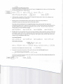
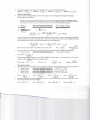
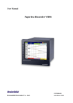
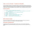
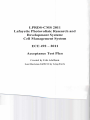
ATP T001 – Verification of Operation of Bypass
Cell Voltage vs. Time - ATP T001
100% SOC
95% SOC
80% SOC
70% SOC
Goes out of bypass now that
it is within 50mV of other cells
3.5
Cell Voltage (V)
3.4
3.3
3.2
More than 50mV
higher than cell
3, enters bypass
3.1
More than 50mV
higher than cells 2 or 3,
enters bypass
3
1
More than 50mV
higher than cells 2 or 3,
enters bypass
2
3
Time(hours)
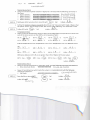
Cell Voltage vs. Time - ATP T001
100% SOC
95% SOC
80% SOC
70% SOC
3.4
Cell Voltage (V)
3.3
3.2
3.1
3
2.9
3
Cells 1, 3 and 4 are
300mV, 325mV and
125mVhigher than cell 2,
Enters bypass
4
Time(hours)
5
Acceptance Test T002:
This test verifies the following requirements:
R002-6: In addition to local controls and indicators, a remote ~ 1 C system shall be able to
2
monitor in detail the voltage, and current of, and state of charge of the aggregate f:SS
battery and every individual cell in the CMS €S&, as well as the overall state of charge of
the pack ~SS J3ararneters
R002-S: The ESS shall be capable of standalone operation. It shall be possible to properly charge
and discharge the ESS without needing an outside computer system for control or
monitoring. Indicators shall be provided that give a basic display operational state
(charge/discharge rate) and charge state (fuel gauge). Controls shall be provided, if
needed, to permit standalone management.
Required Materials:
•
MPJA 9604PS Power Supply
•
Cell Management System (CMS)
o
4-cell pack with OBPP (partially charged)
•
(2) Gold SDP4040D DC Solid State Relay
•
(4) 120 Watt I -Ohm resistors
•
PC running Simulink & RealTerm
•
National Instruments BNC2110 Data Acquisition Board
•
Test Power Cables 1,2,3
•
Test Data Cables 1,2,3
•
Test Voltage Cables 1,2,3,4
•
Test Bypass Cables 1,2,3,4
•
PC to 12C Adaptor (utilizing USB)
•
Agilent Digital Multimeter 34401A
•
16710 TE Infrared Thermometer
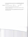
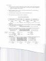
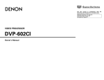
Figure3
to PC - . . .riJj~• • • •
Test Procedure:
•
Maintain the same connection configuration as shown in figure 2 with the following exception :
o Connect the red connector of 'Test Data Cable l' to the 'PC to 12(' Adaptor as displayed in
Figure 3 to enable 12C communication
•
Begin the program RealTerm on the PC, click on the tab which says 12C in order to test the
functionality of the communication.
• The OBPP will begin charging the pack of cells as an initialization cycle
•
12C commands are formed by three bytes of information:
12C Command Format
I
80ard Addr."
Argument 1
I
.~
~ts
Oh~L..\
•
b\t-s) ~ A.< j v ,....,e.<\\ (\ ~ b ,,\-.:.)
\
Initial tests:
a bit5
Change the 12C address of the board currently connected to the 12C interface to be
board..GK~
()\... oc>e:. !.
with the following command in RealTerm:
o Write 12C Address:
•
egg00009 00099090 00010000
O~ '5'-110 OClC~
Query the 12C for the Board Number and Firmware Version ID with the following command in
RealTerm to confirm that the change of 12C address was successful
R002-6
o
Read Board Number:
00010000 OQQ09991 00011001
o
Read Version ID:
0001000000000001000 11090
~/
Version ID: 9>d'O
6h{)()10
Board Number~
0'0 coo \
Fail
Initials:
Fail
Initials:
®/
O'n () ~ \ e, F ~Clb
a h 0 ~ 1 A. f ()~()
Voltage Tests
• Query via 12C for the voltages of the 4 cells by typing in the followin g commands into RealTerm:
o Read Voltage 1:
o Read Voltage 2:
o Read Voltage 3:
o Read Voltage 4:
12CV1:
~.~ L\
~~ .l
V
00010099009QQ09109990001
000100000000008199000010
{lOOlOOOO 00008001 009QQQl1
00010Q09 88890001 Q0000100
12CV2:
3.?:,"
AC. ~
V
12CV3:
O"6~o1.F()DO
0 'n 0 ~ O~ f c ~ 0
CJ \-. 0 ~ 0 ~ r O(:)~
0 ,",OS 0'1 r 0(:)0
;.~ca
f\ CF
V
12CV4:
~.~~
AB~
V
•
Manually measure the voltages across the terminals of each cell in the CMS
DMMV1: 3.~ ~
V DMMV2: ~. ~ L-\ V DMMV3: ;.;'1
V DMMV4: ;,~~
V
SOC & Current Tests
•
Query 12C for the integrated current of the pack and time step by entering the following
commands into RealTerm.
o
6
Because the system was originally designed for the master device to do the calculations for aggregate battery
pack SOC, the number which is returned by this query is not the actual SOC of the pack. The number returned is
the average current which passed through the cell for the duration of the charge/discharge cycle .
or-. 0<6 (J'\
-eOO looao 88880001 00001001
;oe'i8'J:e8e~e8'I geiMEM!(3
fWar4 i:
'i
T:
lINT X T
- - - X 100
capacity F C)C)C)
~.1iIie
min
= 3~O
A
xl
/60 hr
10 A . h
5' r
-
x 100 = .... 10 0/ 0
Observe the current indicator on the MPJA 9604PS Power Supply. Record the value, this will be
used as average current to calculate Soc. Record the amount of time that this charge cycle took
to complete, enter values into the following formula and calculate:
lAve x Time
capacity
Ax
10A.h
x100=
hr
x100=_%
SOC f<om 12C and observaHon differ by less than 10%
•
Pass /
~
~
Initials·
'!J
Query 12C for the current of the pack by entering the following command into RealTerm:
o Read current :
000100000000000100000000
O~DQ,ODfDOO
12C Current :
1..1. 1 'S
A
Oq~,=>
Observe the current indicator on the MPJA 9604PS Power Supply. Test whether the 12C current
is within 10% C (.rA) of the Power Supply current .
'SIX:>,.., '"
PS Current: _ '}
___ A
•
Initials : M
Temperature Test 1 Query 12C for the temperatures of the 4 cells by entering
o Read Temp 1:
000100008080000100000101
o Read Temp 2:
000100000000000100000110
o Read Temp3 :
-0001000000000001 00000111
o Read Temp 4:
0001000900000001 00601609
12C T1:
•
12C ± 1A = PS
J..G; .l
·C
12C T2:
ell .~
·c
12C T3:
the following commands into RealTe rm : 0,", O?> a ':> F caD
0'" 02. a,=> f 000
0 hO <t. C'l-fooO
0 h D C6 0 £ f 000
lol.l ·.1. ·c
12C T4:
.1 ':>.~
·C
lo ~
~ ~o
~D~ 'E~
Manually measure the temperatures of areas near each of the temp sensors on the OBPP using
the 16710 TE Infrared Thermometer
IR T1 :
.l.a., .'\ ·C
IR T2 :
;).1 . ~ 'c
IR T3:
J.'l .~ 'c
IR T4: J."6. <6
'c
?IJ\
MP\tJlJ 1\ l
IN
Ii Cl \) t:
.~
() h D '61 'J.. 00 F F
Master Device Test 1
•
Query 12C and set all power resistors in bypass for 5 minutes with the following commands in
RealTerm:
h u'1> CJ e, CJC)C &
o Bypass Switch 1:
tl0010000 00000008 88801010 OQOQ1811
h<::><t,CC. 00('.)&
o Bypass Switch 2:
808188000000000000001011 OOOOlOH
hC~ at> ooc~
o Bypass Switch 3:
0881800000088000 0000n80 OOOOlOlt
nO~C>f.ooc)~
o Bypass Switch 4:
00018888888008000000110100001011
o
o
o
o
Red Bypass LEDs turned on for 5 min ± 30 sec: G/
R002-6
Fail
Initials:
U
• Setting the re&i§t9Fs il'l B't'pa§5 G3b1S9S tl;}e board to go into "non-automatic" mode.
Observe that
the yellow "status" LED no longer pulses, but remains solid, indicating "non-automatic" mode.
R002-6
Yellow LED solid:
G /
Fail
Initials:
~
Temperature Test 2
• Query 12C for the temperatures of the 4 cells and manually measure temperatures of areas near
each of the temp sensors on the OBPP as in Temperature Test 1:
12C T1:
IR T1:
'?>\. i
·C
" 'lD·C
~1 .:\
12C T2:
IRT2 :
33.1
,a,,\
:1"\.5
·C
12C T3 :
~I) . 3
'o~
·C
IR T3:
.}. L.\.~
·c
·c
~ ')
12C T4:
.1 ·c
lEl5
IR T4 :
J.'5 .'\
·c
Subtract temperatures from Temperatures Test 1 from Temperature Test 2 for both 12C and IR: 12C:
Diff 1:
4,l
·C
, LII _·C
I \_,,Diff 2: _
Diff3:
IR : Diff 1:
3.S
·C
Diff2:_J._·_·C
~
Diff 3: _\._~__ ·C
\0
Diff 4:
\ \. \
Diff 4:
.l
_~
_
. \_·C
Differences between 12C & IR are no greater than 10% of highest of the two values
Diff 1: Pass /
e
Diff 1: Pass /
@
Diff 3: Pass /
®
Diff 1: Pass /
Initials:
•
•
R002-6
·C 0
Jt....f!).;.
Master Device Test 2
Query 12C and set board back to 'automatic mode' with the following command with RealTerm
-eOOll:)l:)l:)l:) tlOOl:)l:)ltle
~ D't> .1.) 0 COO
o Enter Automatic Mode:
0
Query 12C and determine which mode the system is in (automatic/not) with the following
command in RealTerm:
0001BOOO 08888881 00010001
o Get Mode:
Does RealTerm return..Jlx8f7
Fail
Initials:
Fail
Initials:
0,", Mac
YeliowLED~
b\,n\c.\('\)
Does system runs w ithout failure* :
B/
Fail
Initials:
*Board failure criteria are the same as in TOOl
*Software failure: 12C commands remain responsive throughout test.
J.A..
Acceptance Test T003 :
• Cause a common failure in the system and allow a novice to utilize the User Manual in troubleshooting and solving the problem . o A CMS is set up so that the fuse located on the board is one which has been burned out
in a previous experiment being conducted for QA testing. The novice is not aware of
this fact .
o Tell the novice that when the board is correctly hooked up that there is no output from
the power connector, but that the microprocessor is still operating, and can still
communicate via 12C.
o The novice is given the User Manual for the LPRDS-CMS-2011 system and asked to
troubleshoot the malfunctioning board by reading the User Manual and determining
that the reason the board is not working is because of the burned out fuse.
R006-4
Novice was able to solve problem :
& J )Fail
Initials:
¥
• Cause an uncommon failure in the system and allow a system expert to utilize the Maintenance
Manual in troubleshooting and solving the problem .
R006-4
Expert W'5 able to solve problem ,
~rxt~
C5'
Initials : -4.£;::
Fail
: Sti~ AJo!fM~
"
.
LL~_
ATP Test T003:
Expert: Erik Adolfsson
Witness: Will Schlansker
Date: 5/5/11
The pack was first connected to the relays and put into the discharge state. The red discharging LED
blinked a few times and then went solid to indicate the pack was empty. The resistive load was
removed from the pack and I used a multi-meter to measure the voltage of the pack and concluded that
it was in fact, not empty. Next, the expert measured the voltage of each cell and compared each of
these values to the corresponding 12C value. It was immediately apparent that the 12C value for celli
did not match the multi-meter. The expert used the Maintenance Manual to find the appropriate pin
for celli voltage and I checked the input pin to the A2D for celli and saw that it matched the 12C but
not the multi-meter. The expert then narrowed his focus to the differential amplifier between the
voltage for celli and the PIC. He removed the OBPP from the battery pack and pulled up the schematic
for the differential amplifier. He located the differential amplifier for celli and I inspected the chip. It
looked burnt out but to be sure he inspected the resistor values. All 4 resistors in the circuit are lOOK.
The expert used the multi-meter to confirm this and then deduced the TLC-2252 chip was faulty and
needed replacement. Once the chip was replaced, the celli voltage input to the A2D was restored to
the proper value.