1
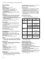
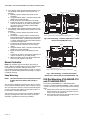
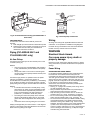
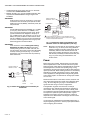
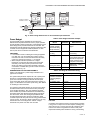
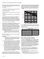
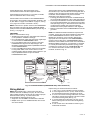
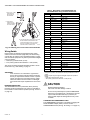
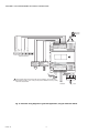
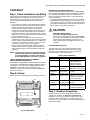
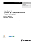
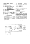
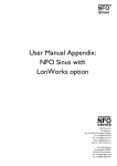
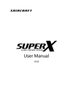
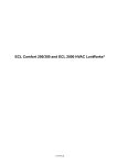
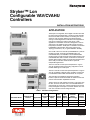
Stryker™ Lon
Configurable VAV/CVAHU
Controllers
INSTALLATION INSTRUCTIONS
APPLICATION
The Stryker™ configurable, direct digital controllers are used
for either pressure-independent or pressure single-duct VAV
terminal units OR constant volume, air-handling unit control
solutions. VAV controllers feature preprogrammed heat/
cooling or reheat algorithms for VAV box control applications
and can be configured to match a wide range of VAV
applications. The CVAHU controller is designed to control a
wide range of air-handling units including single-zone and
heat pump air handlers. All Stryker™ controllers use Echelon
LONWORKS communication technology and the Free
Topology Transceiver (FTT) for great installation flexibility.
One model of the CUL controller (CUL6438SR-CV1) and two
models of the CVL controller (CVL4022AS-VAV1 and
CVL4024NS-VAV1) are available. The CVL4022AS-VAV1
model consists of a VAV controller and a floating actuator. The
CVL4024NS-VAV1 VAV controller model does not include an
actuator. Both models contain an integral microbridge air flow
sensor that provides flow measurement for pressure
independent applications.
The CUL controller controls space temperature in a given
zone by regulating heating and cooling equipment in the air
handler delivering air to that space.
The CVL controller controls the space temperature in a given
zone by modulating a damper and/or regulating a reheat coil
in a Variable Air Volume Box that delivers air to one space.
The controllers are capable of stand-alone operation;
however, optimum functional benefits are achieved when the
network communication capabilities are used.
The Zio (TR71/75) wall modules are used in conjunction with
the CUL and CVL controllers. Zio is an LCD Wall Module to
communicate via a two-wire, polarity insensitive bus with the
Honeywell Spyder and Stryker™ controller families. The CUL
and CVL controllers can be configured in Zio.
Table 1. Controller Configurations
Controller Model
AO
UI
(Universal DI (Digital (Analog
Communication
Output)
Input
Input)
Protocol
Application
CVL4022AS-VAV1
LonWorks
VAV
4
0
2
CVL4024NS-VAV1
CUL6438SR-CV1
LonWorks
VAV
4
0
LonWorks
CVAHU
6
4
DO
(Digital
Output)
Velocity
Series 60
Pressure
Floating
Sensor
(Microbridge) Actuator
2
YES
YES
2
4
YES
NO
3
8 Relays
NO
NO
Put Bar Code Here
62-2029—02
STRYKER™ LON CONFIGURABLE VAV/CVAHU CONTROLLERS
Specifications
Power Failure Backup: 24 hours at 32 to 100° F (0 to 38° C),
22 hours at 100 to 122° F (38 to 50° C)
Accuracy: ±1 minute per month at 77° F (25° C)
Electrical
Rated Voltage: 20-30 Vac; 50/60 Hz
Power Consumption:
100 VA for controller and all connected loads
Controller only Load: 5 VA maximum for models
CUL6438SR-CV1 and CVL4024NS-VAV1
Controller and Actuator Load: 9 VA maximum, model
CVL4022AS-VAV1
External Sensors Power Output: 20 Vdc ±10% @ 75 mA
maximum
Inputs and Outputs
CVL4022AS-VAV1 has four universal input (UI) circuits, two
analog outputs (AO), and two digital Triac outputs (DO).
Two Digital Outputs are reserved for the actuator.
CVL4024NS-VAV1 has four universal input (UI) circuits, two
analog outputs (AO), and four digital Triac outputs (DO).
CUL6438SR-CV1 has six universal inputs (UI), four digital
inputs (DI), three analog outputs (AO), and eight digital
relay outputs (DO).
Environmental
VAV Operating & Storage Temperature Ambient Rating
(models CVL4022AS-VAV1 and CVL4024NS-VAV1):
Minimum 32° F (0° C); Maximum 122° F (50° C)
CVAHU Operating & Storage Temperature Ambient Rating
(model CUL6438SR-CV1)
Minimum -40° F (-40 °C); Maximum 150° F (65.5° C)
Universal Input (UI) Circuits
See Table 2 for the UI specifications.
Table 2. Universal Input Circuit Specifications
Input
Type
Relative Humidity: 5% to 95% non-condensing
Approval Bodies
UL/cUL (E87741) listed under UL916 (Standard for Open
Energy Management Equipment) with plenum rating.
CSA (LR95329-3) listed.
Meets FCC Part 15, Subpart B, Class B (radiated emissions)
requirements.
Meets Canadian standard C108.8 (radiated emissions).
Conforms to the following requirements per European
Consortium standards:
- EN 61000-6-1; 2001 (EU Immunity).
- EN 61000-6-3; 2001 (EU Emissions)
Velocity Pressure Sensor (models CVL4022AS-VAV1 and
CVL4024NS-VAV1)
Operating Range: 0 to 1.5 in. H2O (0 to 374 Pa)
Series 60 Floating Actuator (model CVL4022AS-VAV1)
Rotation Stroke: 95° ± 3° for CW or CCW opening dampers
Torque Rating: 44 lb-in. (5 Nm)
Run Time for 90° rotation: 90 seconds at 60 Hz
Hardware
CPU: Each controller uses a Texas Instruments MSP430 family microprocessor. The processor contains on-chip FLASH
program memory, FLASH information memory, and RAM.
Operating
Range
Room/Zone
Discharge Air
Outdoor Air
Temperature
20K Ohm
NTC
-40° F to 199° F
(-40° C to 93° C)
Outdoor Air
Temperature
C7031Ga
-40° to 120°F
(-40° to 49°C)
C7041Fa
-40° to 250°F
(-40° to 121°C)
PT1000
(IEC751 3850)
-40° F to 199° F
(-40° C to 93° C)
TR23
Setpoint
Potentiometer
500 Ohm
to
10,500 Ohm
-4° DDC to 4° DDC
(-8° DDF to 7° DDF)
or
50° F to 90° F
(10° C to 32° C)
Resistive Input
Generic
100 Ohms
to
100K Ohms
Voltage
Input
Transducer,
Controller
0–10 Vdc
Discrete Input
Dry Contact
closure
OpenCircuit ≥ 3000Ohms
ClosedCircuit < 3000 Ohms
a C7031G
and C7041F are recommended for use with these
controllers, due to improved resolution and accuracy when
compared to the PT1000.
Memory Capacity
Flash Memory: 116 kilobytes with 8 kilobytes available for
user program. The controller is able to retain FLASH memory settings for up to ten (10) years.
RAM: 8 kilobytes
Analog Output (AO) Circuits
ANALOG CURRENT OUTPUTS:
Current Output Range: 4.0 to 20.0 mA
Output Load Resistance: 550 Ohms maximum
ANALOG VOLTAGE OUTPUTS:
Current Output Range: 4.0 to 20.0 mA
Output Load Resistance: 550 Ohms maximum
Digital Triac Output (DO) Circuits ( CVL4022AS-VAV1 and
CVL4024NS-VAV1 only)
Voltage Rating: 20 to 30 Vac @ 50-60Hz
Current Rating: 25 mA to 500 mA continuous, 800 mA (AC
rms) for 60 milliseconds
Digital Relay Output (DO) Circuits (CUL6438SR-CV1 only)
Voltage Rating: 20 to 30 Vac @ 50-60Hz
Current Rating: 0 mA to 1 A continuous, 3.5 A inrush (AC
rms) for 100 milliseconds
Dimensions
CUL6438SR-CV1: H/W/D: 5.45 x 6.85 x 2.26 in.
(13.84 x 17.40 x 5.74 cm)
CVL4022AS-VAV1: H/W/D: 6.60 x 8.28 x 2.26 in.
(16.7 x 21.1 x 5.7 cm)
CVL4024NS-VAV1: H/W/D: 6.60 x 4.75 x 2.26 in.
(15.9 x 12.1 x 5.7 cm)
Real Time Clock
Operating Range: 24 hour, 365 day, multi-year calendar
including day of week and configuration for automatic daylight savings time adjustment to occur at 2:00 a.m. local
time on configured start and stop dates.
62-2029—02
Sensor
Type
2
STRYKER™ LON CONFIGURABLE VAV/CVAHU CONTROLLERS
Status Information
• nvi - Network Variable Input
• nvo - Network Variable Output
The LED on the front of the controller provides a visual
indication of the status of the device. When the controller
receives power, the LED appears in one of the following
allowable states, as described in Table 3.
Hardware
Outputs
VAV Device
Object Type #8010
Table 3. Status LED States.
LED State
OFF
Blink Rate
not applicable
Status or Condition
No power to processor,
LED damaged, low
voltage to board, or
controller damaged.
ON
ON steady;
not blinking
Processor and/or
controller is not operating.
Very slow blink
(continuous)
1 second ON,
1 second OFF
Controller is operating
normally.
Slow blink
(continuous)
0.5 second ON,
0.5 second OFF
Controller alarm is active,
controller in process of
download, or controller
lost its configuration.
nv1
nviSpaceTemp
SNVT_temp_p
nv2
nviSetPoint
SNVT_temp_p
Mandatory
Network
Variables
nv3
nvoSpaceTemp
SNVT_ temp_p
nv4
nvoUnitStatus
SNVT_hvac_status
nv5
nviApplicMode
SNVT_hvac_mode
nv16
nvoEffectSetPt
SNVT_ temp_p
nv6
nviManOverride
SNVT_hvac_overid
nv17
nvoFlowControlPt
SNVT_ flow
Medium blink
(continuous)
0.25 second ON, Controller firmware is
0.25 second OFF loading.
nv7
nviSetPtOffset
SNVT_ temp_diff_p
Fast blink
(continuous)
0.10 second ON, Controller is in manual
0.10 second OFF mode under control of the
PC-based software tool.
nv8
nviOccCmd
SNVT_occupancy
Optional
Network
Variables
nv18 nvoBoxFlow
SNVT_ flow
nv19
nvoTerminalLoad
SNVT_lev_percent
nv20
nvoEnergyHoldOff
SNVT_switch
nviEmergCmd
nv9 SNVT_hvac_emerg
Communications
Each controller uses an FTT transformer-coupled
communications port. The controller's Manchester encoded
data is presented to other controllers and devices on the
LONWORKS® Bus at 78 kilobits per second (kbs) via
Echelon® communication protocol. The transformer-coupled
communications interface offers a much higher degree of
common mode-noise rejection while assuring dc isolation.
The LONWORKS® Bus is polarity insensitive, eliminating
installation errors due to miswiring.
nv10 nviBoxFlow
SNVT_ flow
nv11
nviEnergyHoldOff
SNVT_switch
nv12 nviFanSpeed
SNVT_switch
nviCO2
nv13 SNVT_
ppm
Sylk™ Bus
Sylk is a two wire, polarity insensitive bus that provides both
18 Vdc power and communications between Sylk-enabled
devices. Using Sylk-enabled devices saves I/O on the
controller and is faster and cheaper to install since only two
wires are needed and the bus is polarity insensitive.
nv14
nviHeaterOverid
SNVT_switch
nv15
nviDuctInTemp
SNVT_temp_p
Configuration Properties
nc49 - Send Heartbeat (mandatory)
nc60 - Occupancy Temperature
Setpoints (mandatory)
nc48 - Maximum Receive Time (opt.)
nc52 - Minimum Send Time (opt.)
nc17 - Location (optional)
nc46 - Duct Area (optional)
LONMARK® Functional Profile
The CVL Controllers support the LONMARK® Functional
Profile number 8010 VAV Controller, version 1.0.
nc54 - Minimum Flow (mandatory)
nc51 - Maximum Flow (mandatory)
nc55 - Minimum Flow for Heat (opt.)
nc56 - Minimum Flow Standby (opt.)
nc57 - Nominal Flow (optional)
nc66 - VAV gain (optional)
Manufacturer
Defined
Section
Network Variables Profile
Network variables, as described in Fig. 1 and 2, are
communicated over the LONWORKS® Bus. The controller's
built-in functions provide for the selection of variables, which
are available from/to the network.
Hardware
Input
M33894
Fig. 1. Object Variables List for VAV controllers.
In Fig. 1 and 2 the network variable prefixes have the following
meaning:
3
62-2029—02
STRYKER™ LON CONFIGURABLE VAV/CVAHU CONTROLLERS
BEFORE INSTALLATION
Review the power, input, and output specifications on page ''2''
before installing the controller.
—
Hardware driven by Triac outputs must have a
minimum current draw, when energized, of 25 mA
and a maximum current draw of 500 mA.
—
Hardware driven by the analog current outputs
must have a maximum resistance of 550 Ohms,
resulting in a maximum voltage of 11 volts when
driven at 20 mA.
HARDWARE
OUTPUT
RTU OBJECT TYPE # 8030
nv1
nv2
nviSpaceTemp
SNVT_temp_p
nviSetPoint
SNVT_temp_p
nviApplicMode
nv5 SNVT_hvac_mode
nv6
nv3
nvoSpaceTemp
SNVT_temp_p
nv4
nvoUnitStatus
SNVT_hvac_status
MANDATORY NETWORK
VARIABLES
nv10 nvoEffectSetPt
SNVT_temp_p
nviOccCmd
SNVT_occupancy
OPTIONAL NETWORK
VARIABLES
nv7
nviSetPtOffset
SNVT_temp_p
nv8
nviOutsideTemp
SNVT_temp_p
nv9
nviOutsideRH
SNVT_lev_percent
If resistance exceeds 550 Ohms, voltages up to 18 Vdc are
possible at the analog output terminal.
nv11 nvoOutsideTemp
SNVT_temp_p
nv12
INSTALLATION
The controller must be mounted in a position that allows
clearance for wiring, servicing, removal, connection of the
LonWorks® Bus Jack, and access to the Neuron® Service Pin
(see Fig. 16 on page 14). The controller may be mounted in
any orientation.
nvoOutsideRH
SNVT_lev_percent
nv16 nvoCO2
SNVT_ppm
nviSpaceRH
nv13 SNVT_lev_percent
IMPORTANT NOTE:
nviCO2
nv14 SNVT_ppm
Avoid mounting in areas where acid fumes or other
deteriorating vapors can attack the metal parts of the
controller, or in areas where escaping gas or other explosive
vapors are present (see Fig. 4-Fig. 5 on page 6 for mounting
dimensions).
nviEmergCmd
nv15 SNVT_hvac_emerg
CONFIGURATION PROPERTIES
nc49 - SEND HEARTBEAT (MANDATORY)
nc60 - OCCUPANCY TEMPERATURE SETPOINTS (MANDATORY)
nc48 - MAXIMUM RECEIVE TIME (OPTIONAL)
nc17 - LOCATION (OPTIONAL)
nc42 - CO2LIMIT (OPTIONAL)
Mount Actuator onto Damper Shaft
(CVL4022AS-VAV1 only)
MANUFACTURER
DEFINED
SECTION
HARDWARE
INPUT
The CVL4022AS-VAV1 controller includes the direct-coupled
actuator with Declutch mechanism, which is shipped hardwired to the controller. The actuator mounts directly onto the
VAV box damper shaft and has up to 44 lb-in. (5 Nm) torque,
90-degree stroke, and 90 second timing at 60 Hz. The
actuator is suitable for mounting onto a 3/8 to 1/2 in. (10 to 13
mm) square or round VAV box damper shaft. The minimum
VAV box damper shaft length is 1-9/16 in. (40 mm).
M34860
Fig. 2. Object variables for CVAHU controllers.
Accessories
• 201052A, B, C Auxiliary Switches (one, two or three
switches)
• 209541B Termination Module
• C7041B, C, D, P, R Air Temperature Sensor (indoor)
• C7770A Air Temperature Sensor (indoor/plenum)
• C7031G Air Temperature Sensor (outdoor)
• C7041F Air Temperature Sensor (outdoor)
• Q7751A,B Router (configured as a repeater)
• Q7752A,B Serial Interface Adapter
• TR7X Wall Module
• TR2X Wall Module
• C7400A Enthalpy Sensor
• P7640 Pressure Transducer Family
• C7262 CO2 Sensor Family
• C7600 Humidity Sensor Family
• H7625, H7635, and H7655 Humidity and Temperature
Sensors
Refer to the "Sensors Product Overview," form 63-9285, for
additional accessories.
62-2029—02
The two mechanical end-limit set screws control the amount
of rotation from 12° to 95°. These set screws must be securely
fastened in place. To ensure tight closing of the damper, the
shaft adapter has a total rotation stroke of 95° (see Fig. 1).
NOTE: The actuator is shipped with the mechanical endlimit set screws set to 95 degrees of rotation.
Adjust the two set screws closer together to
reduce the rotation travel. Each "hash mark" indicator on the bracket represents approximately
6.5° of rotation per side.
NOTE: The Declutch button, when pressed, allows you to
rotate the universal shaft adapter (see Fig. 3).
IMPORTANT:
Determine the damper rotation and opening angle prior to
installation. See Fig. 4 and 4 on page 5 for examples.
4
STRYKER™ LON CONFIGURABLE VAV/CVAHU CONTROLLERS
3.
UNIVERSAL SHAFT
CLAMPING BOLTS (2)
UNIVERSAL
SHAFT ADAPTER
4.
MECHANICAL
END LIMIT SET
SCREWS (2)
Determine the direction the damper shaft rotates to
open the damper (CW or CCW) (see Fig. 4). Typically,
there is an etched line on the end of the damper shaft
that indicates the position of the damper. In Fig. 2, the
indicator shows the damper open in a CW direction.
Determine the damper full opening angle (45, 60, or 90
degrees). In Fig. 4, the damper is open to its full open
position of 90 degrees.
TYPE A DAMPER
AIR
FLOW
DECLUTCH
BUTTON
CW TO OPEN, CCW TO CLOSE
TYPE B DAMPER
M23568A
AIR
FLOW
Fig. 3. Series 60 Floating Actuator
IMPORTANT: Mount actuator flush with damper housing or
add a spacer between the actuator mounting surface and
damper box housing.
CCW TO OPEN, CW TO CLOSE
Fig. 5. Determining the rotation direction (CW or CCW) for
damper opening.
Mounting Actuator onto Damper
Shaft (CVL4022AS-VAV1 only)
DAMPER
DAMPER SHAFT
ROTATES
CLOCKWISE
TO OPEN
M2067C
The unit is shipped with the actuator set to rotate open in the
clockwise (CW) direction to a full 95 degrees. The extra 5
degrees ensures a full opening range for a 90 degree damper.
The installation procedure varies depending on the damper
opening direction and angle:
1. If the damper rotates clockwise (CW) to open, and the
angle of the damper open-to-closed is 90 degrees:
a. Manually open the damper fully (rotate clockwise).
b. Using the Declutch button, rotate the universal shaft
adapter fully clockwise.
c. Mount the actuator to the VAV damper box and
shaft.
d. Tighten the two bolts on the centering clamp (8 mm
wrench; 70.8-88.5 lb-in. [8-10 Nm] torque). When
the actuator closes, the damper rotates CCW 90
degrees to fully close.
2. If the damper rotates clockwise (CW) to open, and the
angle of the damper open-to-closed is 45 or 60 degrees:
a. Manually open the damper fully (rotate clockwise).
b. The actuator is shipped with the mechanical endlimits set at 95 degrees. Adjust the two mechanical
end-limit set screws to provide the desired amount
of rotation. Adjust the two set screws closer together
to reduce the rotation travel.
c. Tighten the two mechanical end-limit screws (Phillips #2 screwdriver; (26.5-31 lb-in. [3.0-3.5 Nm]
torque).
d. Using the Declutch button, rotate the universal shaft
adapter fully clockwise.
e. Mount the actuator to the VAV damper box and
shaft.
f. Tighten the two bolts on the centering clamp (8 mm
wrench; 70.8-88.5 lb-in. [8-10 Nm] torque).
g. When the actuator closes, the damper rotates CCW
either 45 or 60 degrees to fully close.
M23569A
Fig. 4. Damper with 90 degree CW rotation to open.
Before Mounting Actuator onto
Damper Shaft (CVL4022AS-VAV1
only)
Tools required:
• Phillips #2 screwdriver - end-limit set screw adjustment
• 8 mm wrench - centering clamp
Before mounting the actuator onto the VAV box damper shaft,
determine the following:
1. Determine the damper shaft diameter. It must be
between 3/8 in. to 1/2 in. (10 to 13 mm).
2. Determine the length of the damper shaft. If the length
of the VAV box damper shaft is less than 1-9/16 in. (40
mm), the actuator cannot be used.
5
62-2029—02
STRYKER™ LON CONFIGURABLE VAV/CVAHU CONTROLLERS
3.
4.
If the damper rotates counterclockwise (CCW) to open,
and the angle of the damper open-to-closed is 90
degrees:
a. Manually open the damper fully (rotate counterclockwise).
b. Using the Declutch button, rotate the universal shaft
adapter fully counterclockwise.
c. Mount the actuator to the damper box and shaft.
d. Tighten the two bolts on the centering clamp (8 mm
wrench; 70.8-88.5 lb-in. [8-10 Nm] torque). When
the actuator closes, the damper rotates CW 90
degrees to fully close.
If the damper rotates counterclockwise (CCW) to open,
and the angle of the damper open-to-closed is 45 or 60
degrees:
a. Manually open the damper fully (rotate counterclockwise).
b. The actuator is shipped with the mechanical endlimits set at 95 degrees. Adjust the two mechanical
end-limit set screws to provide the desired amount
of rotation. Adjust the two set screws closer together
to reduce the rotation travel.
c. Tighten the two mechanical end-limit screws (Phillips #2 screwdriver; (26.5-31 lb-in. [3.0-3.5 Nm]
torque).
d. Using the Declutch button, rotate the universal shaft
adapter fully counter-clockwise.
e. Mount the actuator to the VAV damper box and
shaft.
f. Tighten the two bolts on the centering clamp (8 mm
wrench; 70.8-88.5 lb-in. [8-10 Nm] torque).
g. When the actuator closes, the damper rotates CW
either 45 or 60 degrees to fully close.
DEPTH IS 2-1/4 (57)
4-13/16 (122)
4-1/8 (105)
4-13/16 (122)
4-1/8 (105)
1 1 1 1 1 1 1 2 2 2 2 2
3 4 5 6 7 8 9 0 1 2 3 4
1 1 1 1 1 1 1 2 2 2 2 2
3 4 5 6 7 8 9 0 1 2 3 4
6-1/4
159)
5-7/8
(149)
6-1/4
(159)
5-7/8
(149)
1 1
1 2 3 4 5 6 7 8 9 0 1 2
1 1
1 2 3 4 5 6 7 8 9 0 1 2
3/16 (4.5) PANEL MOUNTING HOLE (4X)
NOTE: CONTROLLER CAN BE MOUNTED IN ANY ORIENTATION.
M28649
Fig. 6. Panel mounting - controller dimensions in inches
(mm) for CVL4024NS-VAV1 only.
4-1/8
(105)
8-9/32
(211) 1-15/16
(49)
27/32
(21)
1 1 1 1 1 1 1 1 1 1 2
9 0 1 2 3 4 5 6 7 8 9 0
6-1/4
(159)
5-7/8
(149)
Mount Controller
6-9/32
(159)
1 2 3 4 5 6 7 8
NOTE: The controller may be wired before mounting to a
panel or DIN rail. Terminal blocks are used to make all wiring
connections to the controller. Attach all wiring to the
appropriate terminal blocks (See “Wiring” on page 7). See Fig.
6 and 7 for panel mounting dimensions. See Fig. 8 on page 7
for DIN rail mounting.
3/16 (4.5) PANEL
MOUNTING HOLE (4X)
DEPTH IS
2-1/4 (57)
NOTE: CONTROLLER CAN BE MOUNTED IN ANY ORIENTATION.
M28648
Fig. 7. Panel mounting - controller and actuator
dimensions in inches (mm) for CVL4022AS-VAV1 only.
Panel Mounting
NOTE: The controller enclosure is constructed of a plastic base plate and a plastic factory-snap-on
cover.
DIN Rail Mounting (CUL6438SR-CV1
and CVL4024NS-VAV1)
The controller is designed so that the cover does not need to
be removed from the base plate for either mounting or wiring.
The controller mounts using four screws inserted through the
corners of the base plate. Fasten securely with four No. 6 or
No. 8 machine or sheet metal screws.
To mount the CUL6438SR-CV1 or CVL4024NS-VAV1
controller on a DIN rail [standard EN50022; 1-3/8 in. x 9/32 in.
(7.5 mm x 35 mm)], refer to Fig. 8 and perform the following
steps:
1. Holding the controller with its top tilted in towards the
DIN rail, hook the two top tabs on the back of the controller onto the top of the DIN rail.
2. Push down and in to snap the two bottom flex connectors of the controller onto the DIN rail.
The controller can be mounted in any orientation. Ventilation
openings are designed into the cover to allow proper heat
dissipation, regardless of the mounting orientation.
62-2029—02
6
STRYKER™ LON CONFIGURABLE VAV/CVAHU CONTROLLERS
.
TOP TABS
AIR FLOW
PICKUP
CONNECTOR
TUBING
DIN RAIL
RESTRICTOR
PORT
RESTRICTOR
PORT
ΔP
UI-4
COM
UI-3
UI-2
COM
UI-1*
AO-2
COM
AO-1
COM
DO-2
DO-1
1 1 1 1 1 1 1 2 2 2 2 2
3 4 5 6 7 8 9 0 1 2 3 4
COM
DO-4
COM
DO-3
NET-2
NE1-2
S-BUS 2
S-BUS 1
20VDC
EGND
24VAC COM
24VAC
BOTTOM FLEX
CONNECTORS
M16815A
1 1
1 2 3 4 5 6 7 8 9 0 1 2
M33633
Fig. 8. Controller DIN rail mounting (CVL4024NS-VAV1 is
shown here).
Fig. 9. Air flow pickup connections
Wiring
IMPORTANT NOTE:
To remove the controller from the DIN rail, perform the
following:
1. Push straight up from the bottom to release the top tabs.
2. Rotate the top of the controller out towards you and pull
the controller down and away from the DIN rail to
release the bottom flex connectors.
All wiring must comply with applicable electrical codes and
ordinances, or as specified on installation wiring diagrams.
Controller wiring is terminated to the screw terminal blocks
located on the top and the bottom of the device.
WARNING
Piping (CVL4022AS-VAV1 and
CVL4024NS-VAV1 only)
Electrical Shock Hazard.
Can cause severe injury, death or
property damage.
Air flow Pickup
Connect the air flow pickup to the two restrictor ports on the
controller (see Fig. 9).
Disconnect power supply before beginning wiring or making
wiring connections, to prevent electrical shock or equipment
damage.
NOTES:
— Use 1/4 inch (6 mm) outside diameter, with a 0.040 in.
(1 mm) wall thickness, plenum-rated1219 FR (94V-2)
tubing.
— Always use a fresh cut on the end of the tubing that
connects to the air flow pickups and the restrictor ports
on the controller.
Power Wiring
GUIDELINES FOR POWER WIRING
For multiple controllers operating from a single transformer,
the same side of the transformer secondary must be
connected to the same power input terminal in each device.
The earth ground terminal must be connected to a verified
earth ground for each controller in the group (see Fig. 12 on
page 9). Controller configurations are not necessarily limited
to two devices, but the total power draw, including
accessories, cannot exceed 100 VA when powered by the
same transformer (U.S. only).
• See Fig. 11 on page 8 for controller power wiring used in
UL 1995 equipment (U.S. only).
• Many controllers require all loads to be powered by the
same transformer that powers the controller.
• Keep the earth ground connection wire run as short as
possible (refer to Fig. 10-Fig. 12 beginning on page 8).
• Do not connect earth ground to the controller's digital or
analog ground terminals (refer to Fig. 10 and Fig. 12).
• Do not connect the universal input COM terminals, analog
output COM terminals or the digital input/output COM
terminals to earth ground. Refer to Fig. 10-12 for wiring
examples. The 24 Vac power from an energy limited Class
II power source must be provided to the controller. To
conform to Class II restrictions (U.S. only), the transformer
must not be larger than 100 VA. Fig. 10 depicts a single
controller using one transformer.
Connect the high pressure or upstream tube to the plastic
restrictor port labeled (+), and the low pressure or
downstream tube to the restrictor port labeled (-). See labeling
in Fig. 9. When twin tubing is used from the pickup, split the
pickup tubing a short length to accommodate the connections.
NOTES:
— If controllers are mounted in unusually dusty or dirty
environments, an inline, 5-micron disposable air filter
(use 5-micron filters compatible with pneumatic controls) is recommended for the high pressure line
(marked as +) connected to the air flow pickup.
— The tubing from the air flow pickup to the controller
should not exceed three feet (0.914 m). Any length
greater than this will degrade the flow sensing accuracy.
— Use caution when removing tubing from a connector.
Always pull straight away from the connector or use diagonal
cutters to cut the edge of the tubing attached to the connector.
Never remove by pulling at an angle.
7
62-2029—02
STRYKER™ LON CONFIGURABLE VAV/CVAHU CONTROLLERS
• Unswitched 24 Vac power wiring can be run in the same
conduit as the LONWORKS® Bus cable.
• Maintain at least a 3 in. (76 mm) separation between Triac
outputs and LONWORKS® Bus wiring throughout the
installation.
ΔP
UI-4
COM
UI-3
UI-2
COM
UI-1*
AO-2
COM
AO-1
COM
DO-2
DO-1
1 1 1 1 1 1 1 2 2 2 2 2
3 4 5 6 7 8 9 0 1 2 3 4
IMPORTANT
Power must be off prior to connecting to or removing
connections from the 24 Vac power (24 Vac/24 Vac
COM), earth ground (EGND), and 20 Vdc power (20
Vdc) terminals.
1 1
1 2 3 4 5 6 7 8 9 0 1 2
TRANSFORMER
COM
IMPORTANT
Use the heaviest gauge wire available, up to 14 AWG
(2.0 sq mm), with a minimum of 18 AWG (1.0 sq
mm), for all power and earth ground wiring. Screwtype terminal blocks are designed to accept up to
one 14 AWG (2.0 sq mm) conductor or up to two 18
AWG (1.0 sq mm) conductors. More than two wires
that are 18 AWG (2.0 sq mm) can be connected with
a wire nut. Include a pigtail with this wire group and
attach the pigtail to the terminal block.
24 VAC
LINE VOLTAGE
GREATER
THAN 150 VAC
1
UI-4
COM
UI-3
UI-2
COM
UI-1*
AO-2
COM
AO-1
COM
DO-2
DO-1
COM
DO-4
COM
DO-3
NET-2
NE1-2
S-BUS 2
S-BUS 1
20VDC
EGND
24VAC COM
24VAC
Before wiring the controller, determine the input and output
device requirements for each controller used in the system.
Select input and output devices compatible with the controller
and the application. Consider the operating range, wiring
requirements, and the environment conditions when selecting
input/output devices. When selecting actuators for modulating
applications, consider using floating control. In direct digital
control applications, floating actuators will generally provide
control action equal to or better than an analog input actuator
for lower cost.
1 1
1 2 3 4 5 6 7 8 9 0 1 2
EARTH
GROUND
(TERMINAL 3)
TRANSFORMER
OUTPUT
DEVICE
POWER
IF THE CONTROLLER IS USED IN UL 1995 EQUIPMENT AND THE
PRIMARY POWER IS MORE THAN 150 VOLTS, GROUND 24 VAC COM
SIDE OF TRANSFORMER SECONDARY.
M33635
Power
ΔP
24 VAC
OUTPUT
DEVICE
POWER
NOTE: More than one controller can be powered by a single
transformer. Fig. 12 shows power wiring details for
multiple controllers.Controller configurations are not
necessarily limited to three devices, but the total
power draw, including accessories, cannot exceed
100 VA when powered by the same transformer (U.S.
only). For power wiring recommendations, see
"Power" below.
1 1 1 1 1 1 1 2 2 2 2 2
3 4 5 6 7 8 9 0 1 2 3 4
COM
1
EARTH
GROUND
EARTH
GROUND
(TERMINAL 3)
Fig. 11. Transformer power wiring details for one
controller used in UL 1995 equipment (U.S. only).
IMPORTANT
If the controller is used on Heating and Cooling
Equipment (UL 1995, U.S. only) and the transformer primary power is more than 150 volts, connect terminal 2, (the 24 Vac common [24 VAC COM]
terminal) to earth ground (see Fig. 11). For these
applications, only one controller can be powered by
each transformer.
CONNECT POWER TO
TERMINALS 1 AND 2
COM
DO-4
COM
DO-3
NET-2
NE1-2
S-BUS 2
S-BUS 1
20VDC
EGND
24VAC COM
24VAC
CONNECT POWER TO
TERMINALS 1 AND 2
Determine the location of controllers, sensors, actuators and
other input/output devices and create wiring diagrams. Refer
to Fig. 18 and 19 beginning on page 14 for illustrations of
typical controller wiring for various configurations.
M33634
Fig. 10. Power wiring details for one controller per
transformer
The application engineer must review the control job
requirements. This includes the sequences of operation for
the controller, and for the system as a whole. Usually, there
are variables that must be passed between the controllers that
are required for optimum system wide operation. Typical
examples are the TOD, Occ/Unocc signal, the outdoor air
temperature, the demand limit control signal, and the smoke
control mode signal.
It is important to understand these interrelationships early in
the job engineering process, to ensure proper implementation
when configuring the controllers.
62-2029—02
8
STRYKER™ LON CONFIGURABLE VAV/CVAHU CONTROLLERS
.
ΔP
UI-4
COM
UI-3
UI-2
COM
UI-1*
AO-2
COM
AO-1
COM
DO-2
DO-1
UI-4
COM
UI-3
UI-2
COM
UI-1*
AO-2
COM
AO-1
COM
DO-2
DO-1
COM
DO-4
COM
DO-3
NET-2
NE1-2
S-BUS 2
S-BUS 1
20VDC
EGND
24VAC COM
24VAC
COM
DO-4
COM
DO-3
NET-2
NE1-2
S-BUS 2
S-BUS 1
20VDC
EGND
24VAC COM
24VAC
1 1
1 2 3 4 5 6 7 8 9 0 1 2
1 1
1 2 3 4 5 6 7 8 9 0 1 2
COM
120/240
VAC
1 1 1 1 1 1 1 2 2 2 2 2
3 4 5 6 7 8 9 0 1 2 3 4
COM
DO-4
COM
DO-3
NET-2
NE1-2
S-BUS 2
S-BUS 1
20VDC
EGND
24VAC COM
24VAC
CONNECT POWER TO
TERMINALS 1 AND 2
1 1 1 1 1 1 1 2 2 2 2 2
3 4 5 6 7 8 9 0 1 2 3 4
UI-4
COM
UI-3
UI-2
COM
UI-1*
AO-2
COM
AO-1
COM
DO-2
DO-1
1 1 1 1 1 1 1 2 2 2 2 2
3 4 5 6 7 8 9 0 1 2 3 4
1 1
1 2 3 4 5 6 7 8 9 0 1 2
EARTH
GROUND (TERMINAL 3)
EARTH
GROUND (TERMINAL 3)
EARTH
GROUND (TERMINAL 3)
24 VAC
TRANSFORMER
OUTPUT
DEVICE
POWER
M33636
Fig. 12. Power wiring details for two or more controllers per transformer
Power Budget
Table 4. Power budget calculation example
A power budget must be calculated for each device to
determine the required transformer size for proper operation.
A power budget is simply the summing of the maximum power
draw ratings (in VA) of all the devices to be controlled. This
includes the controller itself and any devices powered from the
controller, such as equipment actuators (ML6161 or other
motors) and various contactors and transducers.
Device
IMPORTANT
• If a controller is used on Heating and Cooling Equipment
(UL 1995, U.S. only) and transformer primary power is
more than 150 volts, connect the transformer secondary
common to earth ground (see Fig. 11 on page 8).
• When multiple controllers operate from a single
transformer, connect the same side of the transformer
secondary to the same power input terminal in each
device. The earth ground terminal (terminal 3) must be
connected to a verified earth ground for each controller in
the group (see Fig. 12).
VA
Information
Obtained From
CVL4022AS-VAV1
controller (include
Series 60 Floating
Damper Actuator)
9.0
See “Specifications” on
page 2.
R8242A Contactor
fan rating
21.0
TRADELINE® Catalog
inrush rating
D/X Stages
0.0
For example, assume
cooling stage outputs are
wired into a compressor
control circuit and have
no impact on the budget.
M6410A Steam
Heating Coil Valve
0.7
TRADELINE® Catalog,
0.32A 24 Vac
TOTAL
30.7
Table 5. VA ratings for transformer sizing.
POWER BUDGET CALCULATION EXAMPLE
Table 4 is an example of a power budget calculation for a
typical CVL controller.
Device
The system example above requires 30.7 VA of peak power.
Therefore, a 100 VA AT92A transformer could be used to
power one controller of this type. Because the total peak
power is less than 50 VA, this same transformer could be on
page 11 for illustrations of controller power wiring. See Table 6
for VA ratings of various devices.
For contactors and similar devices, the in-rush power ratings
should be used as the worst case values when performing
power budget calculations. Also, the application engineer
must consider the possible combinations of simultaneously
energized outputs and calculate the VA ratings accordingly.
The worst case, which uses the largest possible VA load,
should be determined when sizing the transformer. Each
controller requires 24 Vac power from an energy-limited Class
II power source. To conform to Class II restrictions (U.S. only),
transformers must not be larger than 100 VA. A single
transformer can power more than one controller.
Description
VA
CVL4022AS-VAV1
Controller and Actuator
controllers and Series
60 Floating Damper
Actuator
9.0
CVL4024NS-VAV1
Controller
5.0
ML684
Versadrive Valve Actuator
12.0
ML6161
Damper Actuator, 35 lb-in.
2.2
ML6185
Damper Actuator SR 50 lb-in
12.0
ML6464
Damper Actuator, 66 lb-in.
3.0
ML6474
Damper Actuator, 132 lb-in.
3.0
R6410A
Valve Actuator
0.7
R8242A
Contactor
21.0
Line-Loss
Controllers must receive a minimum supply voltage of 20 Vac.
If long power or output wire runs are required, a voltage drop
due to Ohms Law (I x R) line-loss must be considered. This
line-loss can result in a significant increase in total power
required and thereby affect transformer sizing. The following
9
62-2029—02
STRYKER™ LON CONFIGURABLE VAV/CVAHU CONTROLLERS
loads. With 100 percent load, the transformer secondary must
supply between 23 and 25 volts to meet the NEMA standard.
When a purchased transformer meets the NEMA standard
DC20-1986, the transformer voltage regulating ability can be
considered reliable. Compliance with the NEMA standard is
voluntary.
example is an I x R line-loss calculation for a 200 ft. (61m) run
from the transformer to a controller drawing 37 VA and using
two 18 AWG (1.0 sq mm) wires.
The formula is:
Loss = [length of round-trip wire run (ft.)] x [resistance in wire
(ohms per ft.)] x [current in wire (amperes)]
27
From specification data:
26
25
18 AWG twisted pair wire has a resistance of 6.52 ohms per
1000 feet.
SECONDARY VOLTAGE
24
Loss = [(400 ft.) x (6.52/1000 ohms per ft.)] x [(37 VA)/(24V)] =
4.02 volts
This means that four volts are going to be lost between the
transformer and the controller. To assure the controller
receives at least 20 volts, the transformer must output more
than 24 volts. Because all transformer output voltage levels
depend on the size of the connected load, a larger transformer
outputs a higher voltage than a smaller one for a given load.
18
17
14
0
50
100
% OF LOAD
200
150
M993
Fig. 13. NEMA Class 2 transformer voltage output limits
The Honeywell transformers listed in Table 5 meet the NEMA
standard DC20-1986.
Table 6. Honeywell transformers that meet NEMA standard DC20-1986
Transformer Type
Although acceptable, the four-volt line-loss in this example is
higher than recommended.
VA Rating
AT40A
40
AT72D
40
AT87A
50
AK3310 Assembly
100
NOTE: The AT88A and AT92A transformers do not meet the
voluntary NEMA standard DC20-1986.
IMPORTANT
No installation should be designed where the lineloss is greater than two volts. This allows for nominal
operation if the primary voltage drops to 102 Vac
(120 Vac minus 15 percent).
Bus Communication Wiring
The maximum LONWORKS® Bus network length is 4,600 ft.
(1,400 m). For LONWORKS® Bus network lengths greater
than the above, see "LONWORKS® Bus Wiring Guidelines,"
form no. 74-2865. The theoretical limit for each LONWORKS®
Bus segment is 60 controllers. Up to 120 controllers can be
configured when the Q7751A,B Router (configured as a
repeater) is used, and the bus must be either singly or doubly
terminated. Each network segment can have a maximum of
one repeater. Actual installations may have a lower limit,
depending on the devices connected.
Use heavier gauge wire for the power run. 14 AWG (2.0
sq mm) wire has a resistance of 2.57 ohms per 1,000 ft.
Using the preceding formula results in a lineloss of only
1.58 volts (compared with 4.02 volts). This would allow
a 40 VA transformer to be used. 14 AWG (2.0 sq mm)
wire is the recommended wire size for 24 Vac wiring.
Locate the transformer closer to the controller. This
reduces the length of the wire run, and the line-loss.
The issue of line-loss is also important in the case of the
output wiring connected to the Triac digital outputs. The
same formula and method are used. Keep all power and
output wire runs as short as practical. When necessary,
use heavier gauge wire, a bigger transformer, or install
the transformer closer to the controller.
Honeywell provided cable types for LONWORKS® Bus
communications wiring are Level IV 22 AWG (0.34 sq mm)
plenum or non-plenum rated unshielded, twisted pair,
stranded conductor wire.
• For non-plenum areas, U.S. part AK3798 (single-pair
stranded) can be used.
• In plenum areas, U.S. part AK3797 (single-pair stranded)
or U.S. part AK3799 (two-pair stranded) can be used.
To meet the National Electrical Manufacturers Association
(NEMA) standards, a transformer must stay within the NEMA
limits. The chart in Fig. 13 shows the required limits at various
62-2029—02
19
15
In the preceding I x R loss example, even though the controller
load is only 37 VA, a standard 40 VA transformer is not
sufficient due to the line-loss. Looking at Fig. 13 a 40 VA
transformer is just under 100 percent loaded (for the 37 VA
controller) and has a secondary voltage of 22.9 volts. (Use the
lower edge of the shaded zone in Fig. 13 that represents the
worst case conditions.) When the I x R loss of four volts is
subtracted, only 18.9 volts reaches the controller. This is not
enough voltage for proper operation. In this situation, the
engineer has three alternatives:
1. Use a larger transformer. For example, if an 80 VA
model is used, an output of 24.4 volts, minus the four
volt lineloss, supplies 20.4V to the controller (see Fig.
13).
3.
21
20
16
Fig. 13 shows this voltage load dependence.
2.
23
22
10
STRYKER™ LON CONFIGURABLE VAV/CVAHU CONTROLLERS
The theoretical limit for each LONWORKS® Bus segment is
60 controllers. Up to 120 controllers can be configured when a
repeater is used, and the bus must be either singly or doubly
terminated. Actual installations may have a lower limit
depending on the devices connected.
• The singly terminated bus must have one 209541B Excel
10 FTT Termination Module for T tap or Star configurations.
• The doubly terminated bus must have two 209541B Excel
10 FTT Termination Modules, one at each end of the daisy
chain (Bus style) wiring run. Note that the Q7751A,B router
(configured as a repeater) has onboard terminating
networks that can be jumper selected on each segment.
• Make sure that neither of the LONWORKS® Bus wires are
grounded.
Contact Echelon Corp. Technical Support for the
recommended vendors of Echelon approved cables.
Communications wiring can be run in a conduit, if needed,
with non-switched 24 Vac or sensor wiring.
Pull the cable to each controller on the LONWORKS® Bus
and connect to the controller's communication terminals 7 and
8. (See Table 7 on page 12 and Table 8 on page 13, and Fig.
16 on page 13 for location of terminals 7 and 8.)
NOTE: Connection for operator access to the LONWORKS®
Bus is provided by plugging the Serial LONTALK® Adapter
(SLTA) connector into the LONWORKS® Bus jack (see Fig. 16
and Fig. 17 on page 13).
NOTE: If a 209541B Termination Module is required at the
controller, connect two of the three termination module wires
to the LONWORKS® Bus terminals 7 and 8, which are
labeled Net-1 and Net-2, on the controller. Selecting the
appropriate two wires depends on the LONWORKS® Bus
network topology. Refer to the "LONWORKS® Bus Wiring
Guidelines," form 74-2865, and the "Excel 10 FTT Termination
Module Installation Instructions," form 95-7554. For example,
on a doubly terminated daisy-chained bus topology, where
controllers are on either end of an LONWORKS® Bus wire
run, mount the termination module on the appropriate
terminals, as shown in Fig. 14.
IMPORTANT
Notes on communications wiring:
• All field wiring must conform to local codes and ordinances
(or as specified on installation drawings).
• Do not bundle device output wires with sensor, digital input
or communications LONWORKS® Bus wires.
• Do not use different wire types or gauges on the same
LONWORKS Bus segment. The step change in line
impedance characteristics causes unpredictable reflections
on the LONWORKS® Bus.
• In noisy (high EMI) environments, avoid wire runs parallel
to noisy power cables, motor control centers, or lines
containing lighting dimmer switches. Keep at least 3 in. (76
mm) of separation between noisy lines and the
LONWORKS® Bus cable.
1 1 1 1 1 1 1 2 2 2 2 2
3 4 5 6 7 8 9 0 1 2 3 4
UI-4
COM
UI-3
UI-2
COM
UI-1*
AO-2
COM
AO-1
COM
DO-2
DO-1
UI-4
COM
UI-3
UI-2
COM
UI-1*
AO-2
COM
AO-1
COM
DO-2
DO-1
COM
DO-4
COM
DO-3
NET-2
NE1-2
S-BUS 2
S-BUS 1
20VDC
EGND
24VAC COM
24VAC
COM
DO-4
COM
DO-3
NET-2
NE1-2
S-BUS 2
S-BUS 1
20VDC
EGND
24VAC COM
24VAC
COM
DO-4
COM
DO-3
NET-2
NE1-2
S-BUS 2
S-BUS 1
20VDC
EGND
24VAC COM
24VAC
1 1 1 1 1 1 1 2 2 2 2 2
3 4 5 6 7 8 9 0 1 2 3 4
UI-4
COM
UI-3
UI-2
COM
UI-1*
AO-2
COM
AO-1
COM
DO-2
DO-1
1 1 1 1 1 1 1 2 2 2 2 2
3 4 5 6 7 8 9 0 1 2 3 4
1 1
1 2 3 4 5 6 7 8 9 0 1 2
1 1
1 2 3 4 5 6 7 8 9 0 1 2
1 1
1 2 3 4 5 6 7 8 9 0 1 2
BROWN
ORANGE
PART NO. 209541B
TERMINATION
MODULE
PART NO. 209541B
TERMINATION
MODULE
BROWN
ORANGE
M33711
Fig. 14. Termination Modules (LONWORKS® daisy chain connections)
Wiring Method
Prepare wiring for the terminal blocks, as follows:
1. 1. Strip 1/2 in. (13 mm) insulation from the conductor.
2. 2. Cut a single wire to 3/16 in. (5 mm). Insert the wire in
the required terminal location and tighten the screw.
3. 3. If two or more wires are being inserted into one terminal location, twist the wires together a minimum of three
turns before inserting them (see Fig. 15).
4. 4. Cut the twisted end of the wires to 3/16 in. (5 mm)
before inserting them into the terminal and tightening
the screw.
5. 5. Pull on each wire in all terminals to check for good
mechanical connection.
NOTE: When attaching two or more wires to the same
terminal, other than 14 AWG (2.0 sq mm), be sure to twist
them together. Deviation from this rule can result in improper
electrical contact (see Fig. 15). Each terminal can
accommodate the following gauges of wire:
• Single wire: from 22 AWG to 14 AWG solid or stranded
• Multiple wires: up to two 18 AWG stranded, with 1/4 watt
wire-wound resistor
11
62-2029—02
STRYKER™ LON CONFIGURABLE VAV/CVAHU CONTROLLERS
Table 7. Description of CVL4022AS-VAV1 and
CVL4024NS-VAV1 wiring terminal connections.
1. STRIP 1/2 IN. (13 MM)
FROM WIRES TO
BE ATTACHED AT
ONE TERMINAL.
Terminal
1/2
(13)
Label
Connection
INPUT POWER & GROUND
2. TWIST WIRES
TOGETHER WITH
PLIERS (A MINIMUM
OF THREE TURNS).
1
24 Vac
24 Vac Power
2
24 Vac COM
24 Vac Power
3
EGND
Earth Ground
4
20Vdc
20 Vdc Power
5
SBUS 1
Sylk
6
SBUS 2
Sylk
NETWORK CONNECTIONS
7
NET-1
8
NET-2
LONWORKS® communications
LONWORKS® communications
DIGITAL OUTPUTSa
9
3. CUT TWISTED END OF WIRES TO 3/16 IN. (5 MM)
BEFORE INSERTING INTO TERMINAL AND
TIGHTENING SCREW. THEN PULL ON EACH
WIRE IN ALL TERMINALS TO CHECK FOR
GOOD MECHANICAL CONNECTION.
M17207A
Fig. 15. Attaching two or more wires at terminal blocks.
DO-3
Digital Output
10
COM
Digital Output
11
DO-4
Digital Output
12
COM
Common
13
DO-1
Digital Output
14
DO-2
Digital Output
15
COM
Common
Wiring Details
ANALOG OUTPUTSb
Each controller is shipped with the digital outputs, which
switch the 24 Vac to the load (High Side). The three analog
outputs (AO) are used to control modulating heating, cooling
and economizer equipment. Any AO may be used as a digital
output, as follows:
• False (0%) produces 0 Vdc, (0 mA)
• True (100%) produces the maximum 11 Vdc (22 mA)
16
AO-1
17
COM
Analog Output
Common
18
AO-2
Analog Output
19
UI-1
UNIVERSAL INPUTS
The wiring connection terminals described in Table 7 and 8
are shown in Fig. 18-22 starting on page 14.
20
COM
Common
21
UI-2
Universal Input
22
UI-3
Universal Input
23
COM
Common
24
UI-4
Universal Input
a
IMPORTANT
If the controller is not connected to a good earth
ground, the controller's internal transient protection
circuitry is compromised and the function of protecting the controller from noise and power line spikes
cannot be fulfilled. This could result in a damaged
circuit board and require replacement of the controller.
Universal Input
b
For the CVL4022AS controller ONLY, terminals 9-12 (DO3, DO4, &
COM) are not present. The actuator is internally hardwired to these terminals.
Analog outputs may be configured as digital outputs and operate as
follows:
– False (0%) produces 0 Vdc, (0 mA)
– True (100%) produces the maximum 11 Vdc (22 mA)
CAUTION
NEURON® SERVICE PIN
The NEURON® Service Pin pushbutton (when pressed)
transmits the Service Message to the network, regardless of
the controller's current mode of operation (see Fig. 16 and 17
on page 13).
Equipment Damage Hazard.
Can cause controller damage or failure.
Do not use any metal object to press the NEURON®
Service Pin. Use a plastic rod or wood device (such as
a pencil with the lead broken off) to press the pin.
Using a metal object can damage the circuitry of the
controller.
LONWORKS BUS CONVENIENCE JACK
The LONWORKS Bus connection is provided by plugging the
Serial LONTALK Adapter (SLTA) connector into the
LONWORKS® Bus Jack (see Fig. 16 and Fig. 17 on page 13).
62-2029—02
12
STRYKER™ LON CONFIGURABLE VAV/CVAHU CONTROLLERS
Table 8. Description of CUL6438SR-CV1 wiring terminal
connections.
Terminal
Label
Connection
TERMINALS 13-24
INPUT POWER & GROUND
24 Vac
24 Vac Power
2
24 Vac COM
24 Vac Power
3
EGND
Earth Ground
4
SHLD
Shield
5
SBUS 1
Sylk
6
SBUS 2
1 1 1 1 1 1 1 2 2 2 2 2
3 4 5 6 7 8 9 0 1 2 3 4
UI-4
COM
UI-3
UI-2
COM
UI-1*
AO-2
COM
AO-1
COM
DO-2
DO-1
1
Sylk
NETWORK CONNECTIONS
NET-1
LONWORKS® communications
8
NET-2
LONWORKS® communications
9
24 Vac Out
10
COM-A
Common
11
COM-B
Common
12
COM-C
Common
13
DO-C1
Digital Output
14
DO-A1
Digital Output
15
DO-A2
Digital Output
16
DO-A3
Digital Output
17
DO-B1
Digital Output
18
DO-B2
Digital Output
19
DO-B3
Digital Output
20
DO-B4
COM
DO-4
COM
DO-3
NET-2
NE1-2
S-BUS 2
S-BUS 1
20VDC
EGND
24VAC COM
24VAC
7
DIGITAL OUTPUTS
24 Vac Power
1 1
1 2 3 4 5 6 7 8 9 0 1 2
TERMINALS 1-12
LONWORKS ® BUS JACK (LABELLED SRV JACK)
NEURON® SERVICE PIN (LABELLED SRV PIN)
M28650
Fig. 16. Controller terminal connections, NEURON®
Service Pin and LONWORKS® Bus Jack for the
CVL4022AS-VAV1, and CVL4024NS-VAV1 (CVL4024NSVAV1 shown).
Digital Output
ANALOG OUTPUTSa
21
AO-1
22
COM
Analog Output
Common
23
AO-2
Analog Output
24
AO-3
Analog Output
25
COM
TERMINALS 21-40
22222222233333333334
12345678901234567890
AO-1
COM
AO-2
AO-3
COM
DI-1
DI-2
COM
DI-3
DI-4
20V DC
UI-1
COM
UI-2
UI-3
COM
UI-4
UI-5
COM
UI-6
Common
DIGITAL INPUTSb
26
DI-1
27
DI-2
Digital Input
Digital Input
28
COM
Common
29
DI-3
Digital Input
30
DI-4
20 Vdc
20 Vdc Power
UNIVERSAL INPUTS
32
UI-1
Universal Input
33
COM
Common
34
UI-2
Universal Input
35
UI-3
Universal Input
36
COM
Common
37
UI-4
Universal Input
38
UI-5
Universal Input
39
COM
Common
40
UI-6
Universal Input
12345678
TERMINALS 1-8
LONWORKS® BUS JACK
(LABELLED SRV JCK)
COM-A
COM-B
COM-C
DO-C1
DO-A1
DO-A2
DO-A3
DO-B1
DO-B2
DO-B3
DO-B4
31
24 VAC OUT
24 VAC
24VAC COM
EGND
SHLD
SBUS1
SBUS2
NET-1
NET-2
Digital Input
ATTACHED DEVICE(S) POWER
11111111112
901234567890
TERMINALS 9-20
NEURON® SERVICE PIN
(LABELLED SRV PIN)
M35003
Fig. 17. Controller terminal connections, NEURON® service
pin and LONWORKS® bus jack for CUL6438SR-CV1.
Wiring Applications (Examples)
a
Analog outputs may be configured as digital outputs and operate as follows:
– False (0%) produces 0 Vdc, (0 mA)
– True (100%) produces the maximum 11 Vdc (22 mA)
b Digital inputs: Open circuit = False; Closed circuit = True
Typical controller wiring for VAV applications (see Fig. 18 and
Fig. 19 beginning page 14).
Typical controller wiring for CVAHU applications (see Fig. 2022 beginning page 16).
13
62-2029—02
STRYKER™ LON CONFIGURABLE VAV/CVAHU CONTROLLERS
AIR FLOW
PICKUP
ΔP
OVERRIDE
LED
3
LON -
LON +
2
SETPT
GND
SENSOR
1
UI-4
COM
UI-3
UI-2
COM
UI-1*
AO-2
COM
AO-1
COM
DO-2
DO-1
1 1 1 1 1 1 1 2 2 2 2 2
3 4 5 6 7 8 9 0 1 2 3 4
4 5 6 7 8 9 10 11 12
TR23 WALL MODULE
COM
DO-4
COM
DO-3
NET-2
NE1-2
S-BUS 2
S-BUS 1
20VDC
EGND
24VAC COM
24VAC
SERIES OR
PARALLEL FAN
CONTACTOR
REHEAT
STAGE
CONTACTORS
1 1
1 2 3 4 5 6 7 8 9 0 1 2
+
–
1
24 VAC
24 VAC
COM
CW
1
EARTH GROUND WIRE LENGTH SHOULD BE HELD TO A MINIMUM. USE THE HEAVIEST
GAUGE WIRE AVAILABLE, UP TO 14 AWG (2.O MM2) WITH A MINIMUM OF 18 AWG (1.O MM2),
FOR EARTH GROUND WIRE.
COM CCW
ML6161 DAMPER
ACTUATOR
LON
NETWORK
M33822
Fig. 18. Controller wiring diagram for typical VAV application, using the TR23 wall module.
62-2029—02
14
STRYKER™ LON CONFIGURABLE VAV/CVAHU CONTROLLERS
TR23 WALL MODULE
LON -
SETPT
3
4
5
OVERRIDE
LON +
2
LED
GND
SENSOR
1
6
7
8
9 10 11 12
AIR FLOW
PICKUP
ΔP
UI-4
COM
UI-3
UI-2
COM
UI-1*
AO-2
COM
AO-1
COM
DO-2
DO-1
1 1 1 1 1 1 1 2 2 2 2 2
3 4 5 6 7 8 9 0 1 2 3 4
COM
DO-4
COM
DO-3
NET-2
NE1-2
S-BUS 2
S-BUS 1
20VDC
EGND
24VAC COM
24VAC
SERIES OR
PARALLEL FAN
CONTACTOR
REHEAT
STAGE
CONTACTORS
1 1
1 2 3 4 5 6 7 8 9 0 1 2
+
–
1
24 VAC
24 VAC
COM
1
EARTH GROUND WIRE LENGTH SHOULD BE HELD
TO A MINIMUM. USE THE HEAVIEST GAUGE WIRE
AVAILABLE, UP TO 14 AWG (2.O MM2) WITH A
MINIMUM OF 18 AWG (1.O MM2), FOR EARTH
GROUND WIRE.
LON
NETWORK
M33826
Fig. 19. Controller wiring diagram for typical VAV application with staged reheat.
15
62-2029—02
STRYKER™ LON CONFIGURABLE VAV/CVAHU CONTROLLERS
DISCHARGE
AIR TEMP
COIL
FREEZE
ECONOMIZER
OUTDOOR
TEMP
SPACE CO2
SENSOR
DIRTY
FILTER
COM-A
COM-B
COM-C
DO-C1
DO-A1
DO-A2
DO-A3
DO-B1
DO-B2
DO-B3
DO-B4
24 VAC
24VAC COM
EGND
SHLD
SBUS1
SBUS2
NET-1
NET-2
24 VAC OUT
AO-1
COM
AO-2
AO-3
COM
DI-1
DI-2
COM
DI-3
DI-4
20V DC
UI-1
COM
UI-2
UI-3
COM
UI-4
UI-5
COM
UI-6
22222222233333333334
12345678901234567890
11111111112
901234567890
12345678
+
–
24 VAC
COOLING
STAGE 2
LON
NETWORK
24 VAC
COM
1
COOLING
STAGE 1
SIMPLE
DEHUMIDIFICATION
FAN
HEATING
STAGE 1
1
HEATING
STAGE 2
EARTH GROUND WIRE LENGTH SHOULD BE HELD TO A MINIMUM. USE THE
HEAVIEST GAUGE WIRE AVAILABLE, UP TO 14 AWG (2.O MM2) WITH A MINIMUM
OF 18 AWG (1.O MM2), FOR EARTH GROUND WIRE.
M35004
Fig. 20. Controller wiring diagram for a typical 2H/2C conventional system
with a modulating economizer and dehumidification.
62-2029—02
16
STRYKER™ LON CONFIGURABLE VAV/CVAHU CONTROLLERS
DISCHARGE
AIR TEMP
COIL
FREEZE
ECONOMIZER
OUTDOOR
TEMP
SPACE CO2
SENSOR
DIRTY
FILTER
COM-A
COM-B
COM-C
DO-C1
DO-A1
DO-A2
DO-A3
DO-B1
DO-B2
DO-B3
DO-B4
24 VAC
24VAC COM
EGND
SHLD
SBUS1
SBUS2
NET-1
NET-2
24 VAC OUT
AO-1
COM
AO-2
AO-3
COM
DI-1
DI-2
COM
DI-3
DI-4
20V DC
UI-1
COM
UI-2
UI-3
COM
UI-4
UI-5
COM
UI-6
22222222233333333334
12345678901234567890
11111111112
901234567890
12345678
+
–
24 VAC
CHANGEOVER
RELAY
LON
NETWORK
24 VAC
COM
HEAT/COOL
STAGE 1
HEAT/COOL
STAGE 2
1
SIMPLE
DEHUMIDIFICATION
FAN
HEATING
STAGE 1
1
HEATING
STAGE 2
EARTH GROUND WIRE LENGTH SHOULD BE HELD TO A MINIMUM. USE THE
HEAVIEST GAUGE WIRE AVAILABLE, UP TO 14 AWG (2.O MM2) WITH A MINIMUM
OF 18 AWG (1.O MM2), FOR EARTH GROUND WIRE.
M35005
Fig. 21. Controller wiring diagram for a typical 2H/2C heat pump system with
auxilliary heat, modulating economizer and dehumidification.
17
62-2029—02
STRYKER™ LON CONFIGURABLE VAV/CVAHU CONTROLLERS
COIL FREEZE
DISCHARGE
AIR TEMP
DIRTY FILTER
OUTDOOR
TEMP
COOLING
SPACE CO2
SENSOR
HEATING
ECONOMIZER
COM-A
COM-B
COM-C
DO-C1
DO-A1
DO-A2
DO-A3
DO-B1
DO-B2
DO-B3
DO-B4
24 VAC
24VAC COM
EGND
SHLD
SBUS1
SBUS2
NET-1
NET-2
24 VAC OUT
AO-1
COM
AO-2
AO-3
COM
DI-1
DI-2
COM
DI-3
DI-4
20V DC
UI-1
COM
UI-2
UI-3
COM
UI-4
UI-5
COM
UI-6
22222222233333333334
12345678901234567890
11111111112
901234567890
12345678
+
–
24 VAC
SIMPLE
DEHUMIDIFICATION
LON
NETWORK
24 VAC
COM
FAN
1
1
EARTH GROUND WIRE LENGTH SHOULD BE HELD TO A MINIMUM. USE THE
HEAVIEST GAUGE WIRE AVAILABLE, UP TO 14 AWG (2.O MM2) WITH A MINIMUM
OF 18 AWG (1.O MM2), FOR EARTH GROUND WIRE.
M35006
Fig. 22. Controller wiring diagram for a typical modulating heat/cool system with
modulating economizer and dehumidification.
62-2029—02
18
STRYKER™ LON CONFIGURABLE VAV/CVAHU CONTROLLERS
CHECKOUT
BROADCAST THE SERVICE MESSAGE
The Service Message allows a device on the LONWORKS®
Bus to be positively identified. The Service Message contains
the controller's Neuron® ID number and node type. This is
used to confirm the physical location of a particular Stryket
device in a building.
• To send the Service Message from the controller, press the
NEURON® Service Pin pushbutton on the controller (see
Fig. 23 and Fig. 16 and 17 on page 13). This button sends
out the Service Message when it is pressed, regardless of
the controller's current mode of operation
Step 1. Check Installation and Wiring
Inspect all wiring connections at the controller terminals, and
verify compliance with installation wiring diagrams. If any
wiring changes are required, first be sure to remove power
from the controller before starting work. Pay particular
attention to:
• 24 Vac power connections. Verify that multiple controllers
being powered by the same transformer are wired with the
transformer secondary connected to the same input
terminal numbers on each controller. Use a meter to
measure 24 Vac at the appropriate terminals (see Fig. 10
on page 8). Controller configurations are not necessarily
limited to three devices, but the total power draw, including
accessories, cannot exceed 100 VA when powered by the
same transformer (U.S. only).
• Be sure that each controller has terminal 3 wired to a
verified earth ground, using a wire run as short as possible
with the heaviest gauge wire available, up to 14 AWG (2.0
sq mm) with a minimum of 18 AWG (1.0 sq mm) for each
controller in the group (see Fig. 12 on page 9).
• Verify that Triac wiring of the digital outputs to external
devices uses the proper load power and 24 Vac common
terminal (digital output common terminals) for High-Side
switching.
CAUTION
Equipment Damage Hazard.
Can cause controller damage or failure.
Do not use any metal object to press the NEURON®
Service Pin. Use a plastic rod or wood device (such as
a pencil with the lead broken off) to press the pin.
Using a metal object can damage the circuitry of the
controller.
CONTROLLER STATUS LED:
The LED on the front of the controller provides a visual
indication of the status of the device. When the controller
receives power, the LED appears in one of the following
allowable states, as described in Table 9.
NOTE: All wiring must comply with applicable electrical
codes and ordinances or as specified on installation wiring diagrams. For wiring run length and
power budget guidelines, see “Power” on page 8".
Table 9. Status LED States
LED State
VERIFY TERMINATION MODULE PLACEMENT
(MULTIPLECONTROLLERS ONLY)
The installation wiring diagrams should indicate the locations
for placement of the 209541B termination module(s). See Fig.
14 on page 11 and refer to the "LONWORKS® Bus Wiring
Guidelines," form 74-2865. Correct placement of the
termination module(s) is required for proper LONWORKS®
Bus communications.
Step 2. Startup
Refer to Fig. 23 and the following text for startup information.
LED
TERMINALS 13-24
UI-4
COM
UI-3
UI-2
COM
UI-1*
AO-2
COM
AO-1
COM
DO-2
DO-1
1 1 1 1 1 1 1 2 2 2 2 2
3 4 5 6 7 8 9 0 1 2 3 4
Blink Rate
Status or Condition
OFF
not applicable
No power to processor,
LED damaged, low
voltage to board, or
controller damaged.
ON
ON steady;
not blinking
Processor and/or
controller is not operating.
Very slow blink 1 second ON,
(continuous)
1 second OFF
Controller is operating
normally.
Slow blink
(continuous)
0.5 second ON,
0.5 second OFF
Controller alarm is active,
controller in process of
download, or controller
lost its configuration.
Medium blink
(continuous)
0.25 second ON, Controller firmware is
0.25 second OFF loading.
Fast blink
(continuous)
0.10 second ON, Controller is in manual
0.10 second OFF mode under control of the
PC-based software tool.
Step 3. Checkout Completion
COM
DO-4
COM
DO-3
NET-2
NE1-2
S-BUS 2
S-BUS 1
20VDC
EGND
24VAC COM
24VAC
At this point the controller is installed and powered. To
complete the checkout, the NIAGARA FRAMEWORK®
application (run on a PC) is used to configure the I/O and
functions of the controller. Refer to the Programming Tool
User Guide, form no. 63-2662, for controller configuration and
programming details.
1 1
1 2 3 4 5 6 7 8 9 0 1 2
TERMINALS 1-12
M33673
Fig. 23. LED location.
19
62-2029—02
STRYKER™ LON CONFIGURABLE VAV/CVAHU CONTROLLERS
WARNING
Fire, Explosion, or Electrical Shock Hazard.
Can cause severe injury, death or property
damage.
Do not attempt to modify the physical or electrical
characteristics of this device in any way. Replace the
controller if troubleshooting indicates a malfunction.
IMPORTANT
To prevent bending or breaking the alignment pins on
longer terminal blocks, insert the screwdriver at
several points to evenly and gradually lift up the terminal block. Insert the screwdriver blade no more
than 1/8 in. (3 mm) to prevent damage to the terminal
block alignment pins on the controller circuit board.
1.
WARNING
Electrical Shock Hazard. Can cause severe injury,
death or property damage.
Disconnect power supply before beginning controller
replacement to prevent electrical shock or equipment
damage.
Terminal Block Removal
To simplify controller replacement, all terminal blocks are
designed to be removed with the wiring connections intact and
then re-installed on the new controller. See Fig. 24 and refer to
the following procedure.
2.
Use a thin-bladed screwdriver to evenly raise the terminal block from its alignment pins:
a. For short terminal blocks (1 to 5 terminals), insert
screwdriver blade in the center of the terminal block
and use a back and forth twisting motion to gently
raise the terminal block from its alignment pins 1/4
in. (6.35 mm).
b. For long terminal blocks (6 or more terminals), insert
screwdriver blade on one side of the terminal block
and gently rotate the blade 1/4 turn. Then, move to
the other side of the terminal block and do the same.
Repeat until the terminal block is evenly raised 1/4
in. (6.35 mm) from its alignment pins.
Once the terminal block is raised 1/4 in. (6.35 mm) from
its alignment pins, grasp the terminal block at its center
(for long terminal blocks grasp it at each end) and pull it
straight up.
Controller Replacement
Perform the following to replace the controller:
1. Remove all power from the controller.
2. Remove the terminal blocks (See Fig. 24).
3. Remove the old controller from its mounting.
SHORT TERMINAL BLOCK
LONG TERMINAL BLOCK
Fig. 24. Removing terminal blocks
M23563A
IMPORTANT
(FOR CONTROLLERS MOUNTED TO A DIN RAIL):
1. Push straight up from the bottom to release the top pins.
2. Rotate the top of the controller outwards to release the
bottom flex connectors.
3. Mount the new controller (See "“Mount Controller” on
page 6).
4. Replace the terminal blocks:
a. Insert each terminal block onto its alignment pins.
b. Press straight down to firmly seat it.
c. Repeat for each terminal block.
5. Restore power to the controller.
6. Perform "Checkout.”
By using this Honeywell literature, you agree that Honeywell will have no liability for any damages arising out of your use or modification to,
the literature. You will defend and indemnify Honeywell, its affiliates and subsidiaries, from and against any liability, cost, or damages,
including attorneys’ fees, arising out of, or resulting from, any modification to the literature by you.
Automation and Control Solutions
Honeywell International Inc.
1985 Douglas Drive North
Golden Valley, MN 55422
customer.honeywell.com
® U.S. Registered Trademark
© 2013 Honeywell International Inc.
62-2029—02 KK Rev. 09-13
Printed in United States