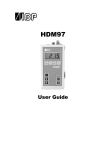
1
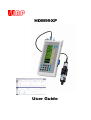
HDM99XP
User Guide
Preface
The information contained in this is subject to change without notice. IBP Medical GmbH, its distributors and subsidiaries take no
responsibility for any errors or omissions in this document. The contained software is being delivered on the basis of a general licence
contract or in single license. Use or reproduction of the software is allowed only in agreement with the contractual arrangements.
Whoever transfers this software and/or this manual on magnetic tape, diskette or any other media, except for the purpose of own use,
without written authorization of the IBP Medical GmbH, is liable to prosecution.
Copyright (C) 1997…2008 IBP Medical GmbH.
All rights reserved
Publishers:
IBP Medical GmbH
Ikarusallee 15
D 30179 Hannover
Germany
IBP Medical Inc
4113 W. St. Charles Ave.
Phoenix, AZ 85041
USA
Phone:
Fax:
+49 511 651647
+49 511 652284
1-866-214-5579
1-866-243-0187
Internet:
E-Mail:
http://www.ibpmt.com
[email protected]
http://www.ibpmedical.com
[email protected]
Manual author:
Dipl. Ing. Werner Pfingstmann
Christopher Weed
Rev. 1. June 2003
Rev. 2. October 2003
Rev. 3 October 2007
Rev. 4 December 2007
Rev. 5 June 2007
Symbols for battery charging, data transfer and battery charger added
High Resolution reading for Conductivity and Pressure
Temperature Coefficiant Nikkiso Bicarbonate modified to 2.20%/°C
CE mark added
HDMView replaced by IBPView
This user guide is only valid for following software releases:
HDM99XP
IBPView
V 4.5 bis 4.59
V 2.0
0482
Safety Instructions
For your own safety, and the safety of your patients, follow these important safety
instructions as well as other safety instructions noted throughout this User Guide.
• Please read the User Guide in its entirety before using the HDM99XP.
• Keep away the device from unauthorized persons.
• Never use the HDM99XP on a dialysis machine to which a patient is connected.
• Never use the HDM99XP on a dialysis machine with a connected battery charger.
• Never use the HDM99XP in place of the hemodialysis machine’s primary sensors.
• Operate the instrument only in a dry environment, and do not touch it with damp hands.
• Ensure that no fluids intrude into the interior of the device or into the sockets at the front.
• Apply a clean transducer protector to the nozzle for the pressure measurement.
• Verify accurate function of the meter before taking measurements or whenever inaccurate
readings are suspected.
• Avoid a discharge of static electricity over the sockets. It could lead to the destruction of your
instrument. Before touching the sockets and lines that are connected with them, dissipate any
static electric charge that may be present in your body.
• Only calibrate the HDM99XP if you have understood the consequences to their full extent. Use
only the recommended standards later in this manual.
• Do not use abrasive cleaning agents and/or full strength bleach or acid to clean HDM99XP or
the electrodes as this will cause damages.
• Voltages above 40 V can be dangerous. Take extreme care while working with higher voltages.
• To avoid electrical shocks, and/or damage to your measuring system, do not apply excess
voltages above 40 V to the instrument.
• Do not open the device.
• To avoid current loops use the RS232-Interface only with notebooks which are not connected
with the battery charger.
1
Table of Content
Introduction..................................................................................................................................................... 2
Applications for use ....................................................................................................................................... 2
EC DECLARATION OF CONFORMITY .......................................................................................................... 3
Delivery Content ............................................................................................................................................. 4
Warranty .......................................................................................................................................................... 5
Product Overview ........................................................................................................................................... 6
Measuring Channels .................................................................................................................................... 6
Battery Charger ............................................................................................................................................ 7
Flow Through Adapter ................................................................................................................................. 7
Switching on the unit .................................................................................................................................... 8
Main Menu.................................................................................................................................................... 8
Info and charge state.................................................................................................................................... 9
General Display Symbols ............................................................................................................................. 9
Language ................................................................................................................................................... 10
Switch-off time............................................................................................................................................ 10
Adjust-reset ................................................................................................................................................ 11
System Error Message ................................................................................................................................. 12
#1 MEM – Memory Error ............................................................................................................................ 12
#2 ADC - AD-Converter Error..................................................................................................................... 12
#3 ADJ – Adjustment Error......................................................................................................................... 12
#4 SYS – System Error .............................................................................................................................. 12
MC, ECT – Additional Information.............................................................................................................. 12
Measurement................................................................................................................................................. 13
Temperature measurement........................................................................................................................ 14
Conductivity measurement......................................................................................................................... 15
Temperature Coefficients ........................................................................................................................... 16
Pressure measurement .............................................................................................................................. 18
Further possible measurements................................................................................................................. 19
pH Measurement........................................................................................................................................ 20
Flow measuring .......................................................................................................................................... 22
Frequency – Period time – Counter ........................................................................................................... 23
Pool menu .................................................................................................................................................. 24
Voltage measurement - plotter ................................................................................................................... 24
Voltage measurement – oscilloscope ........................................................................................................ 25
Battery voltage.............................................................................................................................................. 27
Calibration and Verification......................................................................................................................... 28
Handling of Standard Solutions.................................................................................................................. 28
Calibration of the HDM99XP ...................................................................................................................... 29
Temperature Calibration............................................................................................................................. 30
Conductivity Calibration.............................................................................................................................. 31
Pressure Calibration................................................................................................................................... 35
pH Calibration............................................................................................................................................. 36
Flow Calibration.......................................................................................................................................... 38
Voltage Calibration ..................................................................................................................................... 40
Maintenance and Care.................................................................................................................................. 41
Caring for the conductivity/temperature electrode ..................................................................................... 41
Caring for the flow sensor .......................................................................................................................... 41
Battery ........................................................................................................................................................ 41
Specifications ............................................................................................................................................... 44
PC-Interface................................................................................................................................................... 46
RS-232-Interface ........................................................................................................................................ 46
Interface from PC to HDM .......................................................................................................................... 46
Data transfer............................................................................................................................................... 46
Format of Data ........................................................................................................................................... 47
IBPView.......................................................................................................................................................... 48
What is IBPView......................................................................................................................................... 48
Installation .................................................................................................................................................. 49
Quickstart ................................................................................................................................................... 49
Disconnect RS232...................................................................................................................................... 49
Main Window.............................................................................................................................................. 49
Selecting hardware..................................................................................................................................... 50
Assigning graphs to hardware channels .................................................................................................... 51
Introduction
2
Introduction
The HDM99XP is a self-contained hemodialysis test instrument designed for the measurement of
Conductivity
Temperature
Pressure
pH
Flow
Voltage
Frequency
Period time
Pulses
This innovative device has been designed to be user-friendly, reliable, and rugged enough for the demanding
needs of hemodialysis technicians. In addition, the HDM99XP may also be used for environmental
measurement and other non-medical applications.
The measured values are displayed numerically on the instrument’s large screen. The instrument also may be
connected to a computer, and using the supplied software, displayed, stored and analyzed.
Please take a few moments upon initial receipt of your shipment to ensure that all the items listed below have
been included. In the event of a discrepancy, contact your supplier immediately. Be sure to read this User
Guide in its entirety before first using the product.
Applications for use
The HDM99XP may be used by hemodialysis personnel to test the conductivity, temperature, pressure, pH
and flow of the dialysate solution used with hemodialysis delivering systems.
The HDM99XP may also be used to test the conductivity/temperature and pH of acid
and sodium bicarbonate dialysate concentrates and water used in hemodialysis applications.
The HDM99XP may also be used to test the voltage and alternating signals in hemodialysis delivering
systems.
3
Introduction
EC DECLARATION OF CONFORMITY
according to the Council Directive 93/42/EEC concerning medical devices
Manufacturer
IBP Medical GmbH
Ikarusallee 15
30179 Hannover
declare under our sole responsibility that the
following products:
HDM99XP Reference Meter Series
Product Code: 31.0006.XX
X = Depending on Version
meet the provisions of the Council Directive 93/42/EEC
concerning medical devices which apply to them.
Product Classification
II B
Notified Body
Medcert GmbH
Vorsetzen 35
20459 Hamburg
Identification Number
0482
Hannover 10.10.07
Responsible:
Dipl. Ing. Werner Pfingstmann
Introduction
4
Delivery Content
Pos.
Standard
Option
1
HDM99XP
3
2
Conductivity/Temperature Probe (CTP)
3
3
Flow Through Adapter for CTP
3
4
Battery Charger with country specific adapter
3
5
Tube inc. Male Connector for Pressure Measurement
3
6
14.00 mS/cm Conductivity Standard Solution
3
7
Interface Lead Voltage
3
8
Interface Lead Frequency/Period Time/Pulses
3
9
Test prod
3
10
CD with IBPView Demo and User Manual
11
Case
3
12
Flow Probe
3
13
pH Probe with buffer solution pH6, 7 and 8
3
14
CD - IBPView Data Acquisition Software
3
15
USB – RS232 Converter Cable
3
5
Introduction
Warranty
IBP Medical GmbH warrants that it will repair or replace, at its option, any defective or malfunctioning part
without charge for the terms listed below. Parts used for repair or replacement are warranted for the
remaining warranty period only.
The user must deliver, at its own expense, the product to IBP Medical Inc., USA, from any country in USA
or IBP Medical GmbH, Germany from all other countries.
Parts
Warranty Terms*
HDM99XP
24 months
Conductivity/Temperature Probe
24 months
*
from date original purchase of original purchaser
The warranty does not cover:
• Disposable parts as battery or pH electrode
• Annually calibration
• Cell cleaning
• Defects caused by:
1. Modification, alteration, repair or service of the product by anyone
other than IBP Medical or an authorized service center
2. misuse due to negligence or accident
3. operation or maintenance of the product in a manner contrary
to IBP instructions
Any express warranty not provided herein, and any remedy for breach of contract that but for this provision
might arise by implication or operation of law, is hereby excluded and disclaimed. The implied warranties of
merchantability and of fitness for any particular purpose are expressly limited to the terms mentioned above.
Some states do not allow limitations on the duration of an implied warranty, so the above limitation may not
apply to you.
Under no circumstances shall IBP Medical GmbH be liable to the original purchaser or to any other person
for any special or consequential damages, whether arising out of breach of warranty, breach of contract, or
otherwise. Some states do not allow the exclusion or limitation of special or consequential damages, so the
above exclusion or limitation may not apply to you.
This warranty gives you specific legal rights, and you may also have other rights that vary from state to state.
For further warranty information, contact IBP Medical GmbH.
Introduction
6
Product Overview
Flow/Alternating
Signal Connector
Pressure Inlet
Voltage Connector
pH-Connector
Conductivity/Temperature Connector
Measuring Channels
Only use accessories provided with the HDM99XP. Use of other devices may damage the instrument and
will void the warranty.
Conductivity/Temperature Sensor
The Conductivity/Temperature probe is a quadropole design for greater accuracy and longevity than other
designs. Take care to properly align the pins in the connector when attaching the transducer.
Pressure
To avoid damage or inaccurate measurement, ensure that no fluids enter the instrument. We recommend the
use of a Transducer Protector for this purpose.
pH
The input connector is designed exclusively for pH electrodes. It is optimized for glass electrode single-rod
measuring cells with a slope of ∆E of 59mV at 20°C. Its absolute maximum allowable input voltage span
extends from -3 Volts to +3 Volts with respect to BNC Shield. Applying any voltage beyond these
boundaries will possibly destroy the instrument.
Precautions using the pH Probe input
Due to the high sensitivity of the pH input it can not be fully protected against
electrostatic discharge. It can only be protected by plugging the protective cap to its
BNC receptacle. Always attach the protective cap, if the pH input is not used. Do
not leave the input open, otherwise the circuit inside may be damaged. The
minimum input impedance of the input is 10 Tera Ohms (10*1012 Ohms). The
leakage current is typ. 2 femto Amperes (2*10-15) Amperes.
Flow
The input voltage range is +5...+24 V.
Frequency, Periodicity and Events
The input voltage range is +5...+24 V. The form of the signal should be of a rectangular form and has to be
positive.
7
Introduction
Voltage
The sockets are intended only for AC and DC voltages up to ± 40 V. They are protected up
to ± 80 V.
Battery Charger
The HDM99XP is equipped with an internal NiMH battery for extended run times when not connected to the
external charger. The charger provides a 12 V/1500 mA charge to the battery. A message appears on the
display when the battery requires charging.
The charging process could be controlled with the green and red LED on the right side of the meter. The
green LED indicates that the power supply is connected. The red LED indicates fast charging if continuously
switched on and low level charging if blinking. The complete charging cycle takes about 3 hours with empty
batteries.
For maintenance details, consult the maintenance section of this User Guide.
To avoid hazardous voltages in case of a defective battery charger never use
the HDM99XP on a dialysis machine with a connected battery charger.
For security reasons no measurement during battery charging is possible. In this mode you will receive a
display showing the state of the charge. For special applications a special battery charger with extremely low
leakage current (LLC-Charger) is available, which allows measuring during the charge of the battery. The
HDM99XP automatically detects the type of battery charger connected.
Flow Through Adapter
The Conductivity/Temperature Transducer may be used in two ways.
In the Flow-Through Mode (illustrated at left) the user may measure pressure,
temperature and conductivity with the included Flow Through Adapter. The
preferred position of the Hansen connector is vertical, the axial supply is show at
the bottom of the illustration. In the Flow-Through Mode the axial supply is used as
input and the radial supply as output. The pressure probe in the HDM99XP is
fastened to the radial connection above the input. Before any measurements you
must shake the connector to assure that any air within the system escapes.
In the Dip Mode temperature and conductivity can be measured. For this mode
open the screw cap as show in the picture of the connector and extract the
combined electrode. You must not remove the tube covering the probe carrier. Dip
the electrode into the media up to a level above the holes in the covering tube. By
moving the electrode you assure that the trapped air can escape and the temperature
is well balanced.
Nut for opening
Í
Dialysate
pressure
outlet
Never touch the electrode surfaces with your fingers or other
objects.
Ï
Do not buckle the cable of the probe.
The minimum allowed bending radius is m e.g. 3 cm (1¼ inches).
Introduction
8
Switching on the unit
The unit is switched on and off with the keys marked I for on and O for off. The unit also switches itself off
automatically when the switch-off time after the last key activation is over or the battery is fully discharged.
Main Menu
After switching on the device you receive an information menu for approx. two seconds. After that the
system goes back to the last setting. In some cases you will receive the following main menu.
Activation of the function keys leads to
display of the info-menu
display of the measuring menu
display of the calibration menu
display of the installation menu
9
Introduction
Info and charge state
From the root menu via info you receive the info display. There are device specific data including product
name, software version and the serial number of the device. If the system is in charge mode you will receive
the display on right.
General Display Symbols
The symbols below are visible at the top of the display in all modes.
State of battery charge
Current state of battery charge
Data transfer via RS232
Currently a data transfer to an external device is running
Battery charger connected
Introduction
10
Installation
Language
By pressing the function key beside the menu point language you will reach the language choice. With the
keys beside the arrows you can select the desired language for your work with HDM99XP. The selection is
shown inverted. With activation of ok you will return to the installation menu.
After altering the language the entire menu leadership and display appears in the chosen language.
Switch-off time
The switch-off time is the time after the last key activation. At the end of this time the device switches off
automatically.
The activation of the function switch-off leads to a selection of times which can be selected with the arrowkeys. The chosen time is shown inverted and taken over with ok as new switch-off time in the installation
menu. If >--< is chosen, the automatic power shutoff is cleared, the device remains active until it is switched
off manually with the key >OFF<.
11
Introduction
Adjust-reset
With the adjust-reset the calibration values for all measuring channels can be set to basic values. These basic
values are the calibration values of the company conducted calibration. Operate the function key beside this
menu point. You will have to enter a code via the numeric keyboard. This code is 1704. When you confirm
your input with >enter< you will receive the following images:
With the function keys beside the individual measuring channels you can decide on which calibration values
this function should be applied. The calibration values will be reset to basic values.
If for individual parameters the function adjust reset was used, then a new verification is necessary for these
parameter.
The reset of the flow measurement only resets the parameters of the flow sensors 1....7. The possibly existing
calibration values of own sensors remain unchanged.
Introduction
12
System Error Message
When the HDM99XP is switched on, an internal check is initiated. If the check shows no errors the
HDM99XP is started using the menu which was last in use. If the check reveals an error, following error
message (window) is displayed:
An" OK" error display shows that the internal test routine has been completed with no errors found. An
"ERR" in the display shows that a problem has occurred during the check.
#1 MEM – Memory Error
This error is shown when a problem with the memory was detected.
#2 ADC - AD-Converter Error
This error is shown when a problem with the AD-Converter was detected.
#3 ADJ – Adjustment Error
This error is shown when a problem with the calibration data was detected.
#4 SYS – System Error
This error is shown when a general system problem was detected.
Example: Error #2
If one of the errors above is shown do not use the device anymore. The unit needs to be repaired.
MC, ECT – Additional Information
The entry on the display following the MC and ECT are IBP error messages facilitating problem analysis.
When contacting IBP to report an error, please report the messages describing the system error.
13
Calibration and Verification
Measurement
From the main menu over measuring you will receive the following menu:
Examples for measurement displays
Activation of the function keys
F5 leads to the menu for the
parameter setting
F6 leads back to the main menu
The handling of all menus
corresponds to the already
explained operating instructions.
The individual menus and submenus are presented and
explained below.
Calibration and Verification
14
Temperature measurement
Time range
By activation of the function key param. you will receive a menu which allows to change the time range, in
which the course graphic will run through horizontally once. Long term measurements up to twelve hours are
possible. Since you do not have all possible times presented simultaneously, a black beam on the right side
shows that above, or - like in the example - further options hide themselves below.
The selected time range is shown inverted. To change the time range, operate the function keys beside the
arrows upward or downward. When you have selected the suitable time range for your application, return to
the temperature measurement with the activation of ok. The length of the horizontal axis of the graph now
corresponds to the chosen time range.
15
Calibration and Verification
Conductivity measurement
After activation of the function key param. you will get to the menu which allows you to change the time
range (horizontal axis of the graph) or the y-range (vertical axis) and also the temperature coefficient. By
activation of the function key for the range to be changed you see the selection menus.
At the time range long term measurements up to twelve hours are possible. Since you do not have all
possible times presented simultaneously, a black beam on the right side shows that above, or - like in the
example -, further options hide themselves below.
The selected time range is shown inverted. To change the time range, operate the function keys beside the
arrows upward or downward. When you have selected the suitable time range for your application, return to
the temperature measurement with the activation of ok. The length of the horizontal axis of the graph now
corresponds to the chosen time range.
After the choice of the field y-range four fixed measuring ranges can be selected in the already explained
way with the function keys beside the arrows.
The selection „High Resolution“ allows to select the resolution to display.
With activation of the function key ok you arrive back in the conductivity measurement. The vertical axis of
the course graphic as well as the scale length of the beam display now correspond to the measuring range
you have chosen.
The temperature coefficient menu point allows many different setting possibilities. In the parameter menu for
conductivity and also conductivity + temperature, it is possible to choose from a list of preset temperature
coefficients of various dialysis machine manufacturers. These are listed by name.
There is also a standard value of 2.07% / °C and a user value. The user value can be changed in the usual
way in the adjustment menu for conductivity.
The selection „High Resolution“ allows to select the resolution to display.
All settings are permanent until the next change. The selected setting is shown in the measurement menu.
If the conductivity measured is outside this range, OFL will appear on the display.
Calibration and Verification
16
Temperature Coefficients
Temperature Coefficients and Conductivity Measurement
This is a topic that is frequently misunderstood and often neglected in hemodialysis.
A solution’s conductivity will change according to temperature. With increasing temperatures, the measured
solution’s conductivity will increase, too. To achieve meaningful measurement results, the conductivity
value displayed is compensated to 25°C. In other words, the display is always converted to a solution
temperature of 25°C. The temperature coefficient which the displayed value is compensated with is
expressed as %/°C. Unfortunately however, different solutions also have different temperature coefficients.
To achieve an exact display, the instrument will have to be adjusted to the temperature coefficient of the
current solution. The average temperature coefficient for dialysates is 2.07 %/°C.
Listed below are the temperature coefficients used by most major hemodialysis machine manufacturers. We
recommend that you doublecheck this data with documentation from your machine’s manufacturer.
Machine Manufacturer
Temperature Coefficient
Baxter (European Machine)
2.20%/°C
Braun
2.10%/°C
Bellco
2,10%/°C
Braun
2,10%/°C
Fresenius
2,10%/°C
Gambro (AK-Type Machines)
2.07%/°C
Gambro Phoenix
2.07%/°C
Hospal
2.07%/°C
Nikkiso
Bicarbonate conductivity
2.20%/°C
Total conductivity
2.05%/°C
For naturally occurring solutions, a value of 1.97 %/°C is frequently used. Many measuring devices not
specially tailored to dialysis will use this value.
The calculation below shows the drastic effects of an incorrect temperature coefficient.
Example calculation for an incorrect temperature coefficient, using a dialysate with a temperature coefficient
of 2.07 %/°C:
Conductivity of
Solution
mS/cm
Temperature
Instrument
of Solution Temperature Coefficient
°C
%/°C
Instrument
Display
mS/cm
Difference in
Values
%
14.00
37.0
2.07
14.00
0.00
14.00
37.0
1.97
14.17
1.21
Thus, our example illustrates that the user must set the temperature coefficient correctly in order to ensure
accurate measurements.
17
Calibration and Verification
Which temperature coefficient you should use
First of all please double-check the Temperature coefficient with the machine manual.
If you have machines from one manufacturer only in your use the temperature coefficient that the dialysis
machine uses for compensation.
If you have different types of dialysis machines in your unit the best solution is to use a temperature
coefficient of 2.07 %/°C for all machines. This avoids confusion with different readings of the conductivity
on different machines.
Setting the Temperature Coefficient
The HDM99XP enables you to easily set different temperature coefficients. You can choose between eight
fixed settings and a variable value. The fixed values are values of frequently used dialysis machines. The
variable value can be set to any required value.
Calibration and Verification
18
Pressure measurement
Time range
After activation of the function key time range you will get to a menu which allows to change the time range
(horizontal axis of the graph).
Long term measurements up to twelve hours are possible. Since you do not have all possible times presented
simultaneously, a black beam on the right side shows that above, or - like in the example -, further options
hide themselves below.
The selected time range is shown inverted. To change the time range, operate the function keys beside the
arrows upward or downward. When you have selected the suitable time range for your application, return to
the temperature measurement with the activation of ok. The length of the horizontal axis of the graph now
corresponds to the chosen time range.
19
Calibration and Verification
Unit
The unit for the pressure measurement can be chosen. The values are converted when the unit is changed. A
new calibration is not necessary.
The selection of the unit is done in the familiar way with the function keys beside the arrows. With ok you
return to the pressure measurement, where now the results will be shown in the newly chosen unit.
Balancing an offset
Caused by drift of the pressure probe, the pressure display may sway slightly around zero. With the function
tare the display is set to zero. You must not apply pressure to the HDM99XP during this function. This is
assured when the pressure tube is not connected. Then the environmental pressure represents zero.
The choice of the function key tare results in the reset of the display to zero and the automatic return to the
pressure measurement.
High Resolution
The selection „High Resolution“ allows to select the resolution to display.
Further possible measurements
With the option other channels you can shift to a second measuring menu where you have the choice
between two different modes of voltage measurement: the test for pH-value and the control of the charging
state of the accumulators.
If you would like to return to the first measuring menu with conductivity, temperature and pressure
measurement choose other channels again.
Calibration and Verification
20
pH Measurement
Time range
By activation of the function key param. you will receive a menu which allows to change the time range in
which the course graphic will run through horizontally once. Long term measurements up to twelve hours are
possible. Since you do not have all possible times presented simultaneously, a black beam on the right side
shows that above, or -like in the example- further options hide themselves below.
The selected time range is shown inverted. To change the time range, operate the function keys beside the
arrows upward or downward. When you have selected the suitable time range for your application, return to
the temperature measurement with the activation of ok. The length of the horizontal axis of the graph now
corresponds to the chosen time range.
21
Calibration and Verification
Temperature compensation pH-measurement
For the temperature calibration of the pH-measurement the device offers two possibilities. The solution
temperature can be measured via the conductivity and temperature electrode, or entered by hand. The chosen
kind of the calibration is check-marked in the menu point measure t-comp or enter t-comp. If you choose
measure t-comp. no further input is necessary. The temperature will be measured via the measuring cell.
By choice of enter t-comp. you will be asked to enter the solution temperature via the numeric keyboard.
After confirmation with >ENTER< you will return to the menu for the parameter setting
Fundamental information about pH measurement
For measuring pH, a combined electrode is used. Combination pH electrodes are combinations of one
reference electrode and one measuring electrode in a glass tube. The pH value in the dialysate is measured by
an unbreakable pH-electrode. The glass body is protected with a plastic coat and due to the jelly-electrolytefilling, it is maintenance-free. This electrode`s diaphragm must be stored in 3 mol/l KCl-solution. The
protective cap must be refilled every three to four weeks to prevent the electrode from drying out. Before use
the electrode must be checked for exterior damage and crushed glass. Crusts caused by leaking electrolyte
can be removed easily by rinsing with reverse osmosis-treated water. The sample volume should be 100 ml
of dialysate or 1 liter of untreated water. The sample should be poured into a clean glass container with a
tube or hose, coming into as little contact with air as possible. The pH-value must be measured immediately
in the same container. Make sure that the display stabilizes before the value is read. In stirred solutions the
response rate is faster; the value, however, must be measured at resting fluid.
The pH-electrode must be dabbed only with a lint-free cloth and never rubbed dry. Rubbing destroys the
jelly layer on the glass surface which results in a longer response time for the electrode.
Before taking measurements, remove the rubber cap. If the mobility of the plastic part is restricted it can be
released by rinsing with lukewarm water.
Pressure and fluid currents have considerable influence on the pH measurements. Therefore, it is
essential to take the pH measurement in a resting solution at environmental pressure.
Calibration and Verification
22
pH-calibration in the measuring mode
Calibration
Before the adjustment the kind of temperature calibration must be set already.
Prepare two buffer solutions. The two buffers should not differ more than two activation decades. Choose,
for example, pH4 and pH6. Carefully remove the protection hood for the measurement. Rinse and dab the
pH electrode with distilled water before dipping it into the buffer. If necessary wash and dry the temperature
sensor likewise, and put it into the measuring beaker. Wait until the display remains stable, then enter the
pH-value via the numeric keyboard. Confirm your input with > ENTER <. Then wash and dry the electrode
and dip it into the second buffer. When the value of the second buffer is entered, the display shows the actual
calibration. If thereby the graduation (grad) is lower than 85%, the electrode could be worn out and must be
replaced by a new one.
If you try to enter two equal values the reference invalid data appears after confirming with ok; at correct
input the data will be saved, and you will return to the menu for the parameter setting.
Flow measurement
The current flow rate and the amount of flown liquid will be shown. The amount of flown liquid can be
restored to zero by pushing Reset.
23
Calibration and Verification
The Parameter Button leads to the selection menu for the flow rate reduction.
An average flow rate is determined by setting a time (limit) in this display/menu. The selected reduction
value is displayed in the measurements window behind the "Att:' Sign.
Management of different sensors
For the measuring of the flow different sensors will be used according to the measuring unit. The HDM99XP
governs up to 15 different sensors. For detecting the different sensors a code is put on them. This code is
used for the internal choice of calibration data. The number of the connected sensors will be shown in the
display.
Any sensor can be used which has an output signal that delivers a frequency proportional to the flow
running. The amplitude at the entrance of the HDM99XP may have a range of 5...24 V. For the current
supply of the sensors 5 V DC/ 10 mA are available at the connection of the flow measuring.
Frequency – Period time – Counter
By operating one of the three functions you get optionally to the measuring menu for frequency, period
duration , or event measuring.
All measurements can be done up to a frequency of 250 kHz. In the event measuring, the counted events can
be reset to zero by operating reset.
Calibration and Verification
24
Pool menu
Pool is a menu in which the following channels are displayed simultaneously:
Conductivity
Temperature
Pressure
Flow
All necessary settings, e.g. the temperature coefficient for the conductivity measurement or the unit for the
pressure measurement, are taken from the corresponding measurement menus and can also only be changed
there.
Voltage measurement - plotter
Time range
25
Calibration and Verification
By activation of the function key param. you will receive a menu which allows to change the time range in
which the graph will run through horizontally once. Long term measurements up to twelve hours are
possible. Since you do not have all possible times presented simultaneously, a black beam on the right side
shows that above, or - like in the example - further options hide themselves below.
The selected time range is shown inverted. To change the time range, operate the function keys beside the
arrows upward or downward. When you have selected the suitable time range for your application, return to
the temperature measurement with the activation of ok. The length of the horizontal axis of the graph now
corresponds to the chosen time range.
Damping
By operating the function key damping you will get a time table with a choice of periods between zero and
ten seconds. Those can be chosen in the usual way with the function keys beside the arrows upward or
downward. By use of the chosen period of time a gliding average value of the measured voltage will be
calculated and put on display.
Please note that voltage sways which are shorter than the selected damping period can not be recorded.
Voltage display
In the beam display the momentary value of the voltage is displayed. The voltage measurement in the plotter
mode is particularly feasible for the measurement of voltages which are subject to no fast sway, therefore DC
voltages and low frequency AC voltages.
Filter
By choice of the function key filter you will receive a time table with periods between zero and 10 seconds
to select. Those can be operated in the familiar way with the function keys beside the arrows. An average
value of the measured voltage over the selected period is calculated and reported. Please note that voltage
sway which is shorter than the selected filter period can not be recorded.
Voltage measurement – oscilloscope
Calibration and Verification
26
Time range
By activation of the function key param. you will receive a menu which allows you to change the time range
in which the graph will run through horizontally once. Long term measurements up to twelve hours are
possible. Since you do not have all possible times presented simultaneously, a black beam on the right side
shows that above, or - like in the example - further options hide themselves below.
The selected time range is shown inverted. To change the time range, operate the function keys beside the
arrows upward or downward. When you have selected the suitable time range for your application, return to
the temperature measurement with the activation of ok. The length of the horizontal axis of the graph now
corresponds to the chosen time range.
Voltage Display
In the beam display the R.M.S. value of the voltage is shown. The voltage measurement in the oscilloscope
mode serves mainly for the measurement of voltages subject to higher frequency, therefore also AC voltages.
Measuring range
By activating the function key y-range it is possible to select a measuring range for the vertical axis of the
graph via the arrow-keys which allows a maximum resolution of the voltage graph. The chosen measuring
range is shown inverted. With the ok-key you transfer it to the voltage measurement.
Trigger
With this function key you will get to a menu where you can adjust the mode of the measurement triggering.
Press the keys beside the arrows until the desired triggering is presented inverted. In detail the options mean:
No trig.
+ AC
- AC
+DC
-DC
The applied voltage is shown without triggering.
The rising edge of the average value of the applied voltage is triggered.
The falling edge of the average value of the applied voltage is triggered.
The rising edge at the zero passage of the voltage is triggered.
The falling edge at the zero passage of the voltage is triggered.
Take over the chosen triggering with the ok-key, and return to the voltage measurement. Please note that a
successful triggering can only take place if a suitable voltage signal is applied. Otherwise >no trigger<
appears in the graphic display.
27
Calibration and Verification
Battery voltage
Charging state of the battery
If you select the function battery you will receive an information display about the battery.
The HDM99XP is equipped with an internal NiMH battery for extended run times when not connected to the
external charger. The charger provides a 12 V/1500 mA charge to the battery. The charging process could
be controlled with the green and red LED on the right side of the meter. The green LED indicates that the
power supply is connected. The red LED indicates fast charging if continuously switched on and low level
charging if blinking. The complete charging cycle takes about 3 hours with empty batteries.
To avoid hazardous voltages in case of a defective battery charger never use
the HDM99XP on a dialysis machine with a connected battery charger.
With activation of the key measuring you will return to the measuring menu.
Calibration and Verification
28
Calibration and Verification
To avoid confusion let us explain first what is calibration and what is verification.
• Calibration is the correction of a measuring channel
• Verification is the checking of the instrument with a known reference value
Anytime a calibration is made to the meter, verification is required to ensure accurate operation. Anytime
that improper function is suspected, verification and/or calibration are required.
Each measurement parameter is calibrated in a slightly different manner, so be sure to read the instructions
carefully before proceeding.
• The conductivity is calibrated by measuring the cell constant. Due to the high linearity of the probe
only one calibration point is necessary for this.
• The temperature and pressure sensors do not drift, no calibration is necessary after manufacturing. The
calibration is done at six points for increased accuracy
• The pH measurement is calibrated at two points.
If at any point during calibration, you are unsure whether you have correctly entered all values, you can exit
without saving any calibration values. After you have done so, no calibration is performed and you can start
again from the beginning. The necessary steps for exiting the calibration procedure are described in detail
below.
If a calibration is incorrect, you have the option of accepting the standard values for every measurement
mode. Refer to the Standard Values section for details.
Handling of Standard Solutions
IBP Medical standard solutions are produced under ISO13485 quality management. They are traceable to
NIST and PTB Standards Reference Materials and are sealed with tamper-evident packaging.
To ensure standard solution and calibration/verification accuracy
•
•
•
•
•
•
•
•
Keep solutions tightly capped to avoid evaporation
Do not return used solutions to the storage bottle
Do not remove solutions from their original bottle
Keep the solutions in a cool place
Use only fresh reference solutions for calibration and verification
Use the solution immediately after pouring, evaporation will cause errors
Discard solution the appropriate number of days after opening the bottle
Discard solution after the expiration date
29
Calibration and Verification
Calibration of the HDM99XP
The entire calibration of the device is software controlled. Operate the function key adjust in the main menu
to reach this function. You will be asked to enter a code via the numeric keyboard. This code is also 1704,
and must be confirmed with >ENTER<. After that, you are in the adjust menu.
The adjustment of the individual channels is slightly different. The pH- and voltage measurement is adjusted
at two points. The temperature and pressure measurement is adjusted at minimally two points, alternatively
up to six points. The advantage of more than two calibration points is the higher precision of the
measurement as the non-linearity of the sensors will be equalized . The sequence of the calibration in
reference to the level of the values is insignificant. Please note, that each value may be entered only once,
since the system does not accept the data otherwise. The display will show invalid data.
The conductivity calibration results from measuring the cell parameter. Only one calibration point is
necessary here.
The calibration of the flow measurement results from measuring of the impulses per liter. Up to 15 different
sensors can be calibrated. Only one calibration point is necessary for this.
Should you be uncertain if you have entered all values correctly at any point in the run of
the calibration of the device, choose the function >cancel<. Then no calibration will be
accomplished, and you can start again.
Should a calibration prove to be incorrect you can reset this calibration by the function calibration reset
within the installation menu.
Calibration and Verification
30
Temperature Calibration
Because these sensors do not drift, normally no calibration is necessary after manufacturing.
The calibration is to be accomplished as follows: Operate the function key temp. and follow the instructions
on the display.
The temperature sensor is dipped into a fluid with known temperature, this temperature is then entered to the
HDM99XP via the numeric keyboard and confirmed with >ENTER<. The calibration points should be at the
following points: 20 °C, 30 °C, 36 °C, 38 °C, 45 °C and 80 °C. After you have entered the last value press
the function key stop input. If a higher precision is required at temperatures around 80 °C you can enter
further calibration points at 60 °C and 85 °C. In this case choose another input.
The calibration value must be entered only if the displayed values are stable.
31
Calibration and Verification
Conductivity Calibration
Reference temperature
The usual reference temperature is 25 °C. For special applications other values can be used.
Use this function only if you are aware of the consequences. By using wrong values you
will get a wrong conductivity value.
You reach this function by calling the menu point ref.-temp. There you can enter the new reference
temperature via the numeric keyboard and confirm it with >ENTER<. By activation of the ok-key the new
reference temperature will be saved in the software.
Calibration and Verification
32
Temperature coefficient
For dialysate, the temperature-coefficient of the solution to be measured is 2.070%. This is the value for
NaCl-Solutions. For special applications this factor can be changed.
Use this function only if you are aware of the consequences. By using wrong values you will get wrong
conductivity values.
You reach this function by calling the menu point temp.-coeff. You can enter the new temperature coefficient
via the numeric keyboard and confirm it with >ENTER<. Pressing the OK button transfers the new
temperature coefficient to the program, but it is not used until it is selected in the parameters menu for
Conductivity and Conductivity + Temperature.
By operating the menu point conductivity range you can choose the correct range with the arrow-keys. While
calibrating the solution should have a temperature of approximately 25 °C. As soon as the measuring value
in the display is stable the calibration value of the solution can be entered by the numeric keys and can be
confirmed with >ENTER<.
After the calibration, all values relevant for the conductivity measuring will be indicated once more. By
operating the ok-key all data will be saved.
33
Calibration and Verification
Measuring of the cell parameter
Before this function can be used, the reference temperature must be adjusted. It is sufficient for the
conductivity calibration to know the cell parameter. If this is not known, or has been changed after longer
use by deposits on the electrode, this function can be used to define the cell parameter newly. Call the
function measure cellpar.in the adjust-menu.
Materials needed: HDM99XP meter with attached conductivity/temperature probe, 14.0 ms/cm
Conductivity Standard Solution, clean glass container.
Calibration and Verification
34
In this function the measuring range will not be adjusted automatically. The adjustment for dialysate should
be in the area of 13...14 mS/cm. Therefore the measuring range must be 0...20 mS/cm. If the measuring
range is too small, the device indicates the overflow with >OFL< above the beam display. Via the menu
point measure conduct you can choose the correct measuring range with the arrow-keys. During the
calibration the standard solution should have a temperature of approx. 25 °C. When the measurement value
in the display is stable, the conductivity value of the standard solution can be entered via the numeric
keyboard and confirmed with >ENTER<. After the calibration, all values relevant for the conductivity
measurement are indicated once more. With the ok-key the data will be saved.
Enter cell parameter
It is sufficient to enter the cell parameter of the electrode if it is known. This is profitable for an exchange of
the electrode. Choose the function input cellpar. Enter the cell parameter via the numeric keyboard and
confirm it with >ENTER<. Subsequently, all values relevant for the conductivity measurement will be
indicated once more. With the ok-key the data will be saved.
35
Calibration and Verification
Pressure Calibration
Because these sensors do not drift, normally no calibration is necessary after manufacturing.
Operate the function key pressure in the adjust-menu. The calibration of the pressure measurement works
like described for the temperature calibration at up to six points. After the input of two points you have the
choice whether to terminate the calibration (function stop input), or to enter further values (function another
input). The pressure probe is applied with known pressure, and then the values will be entered successively
via the numeric keyboard and confirmed with >ENTER<. The calibration points for the measurement on
dialysis machines should be at -400, -100, 0, +100 and +500 mmHg. If you call the function stop input after
your input, the entered values will be indicated once more, and can be taken over with the ok-key.
The calibration values must be entered only if the values on the display are stable. The sequence of the
calibration in reference to the level of the values is insignificant. Please note that each value may be entered
only once since the system does not accept the data otherwise.
Calibration and Verification
36
pH Calibration
Please read the section Fundamental information about pH-measurement.
Temperature compensation of the pH-measurement
For the temperature compensation of the pH-measurement the device offers two possibilities. The solution
temperature can be measured via the conductivity and temperature-electrode, or entered by hand. The chosen
type of the calibration is check-marked in the menu point measure t-comp or enter t-comp. If you select
measure t-comp. no further input is necessary. The temperature will be measured via the measuring cell, and
you will get to the pH-measurement automatically.
By choice of enter t-comp. you will be asked to enter the solution temperature via the numeric keyboard.
After confirmation with >ENTER< you will return to the menu for the parameter setting
By choice of the function calibration you will reach the pH-calibration directly. The device uses 25°C as
default.
37
Calibration and Verification
How to calibrate pH:
Materials needed: HDM99XP meter with attached pH probe, conductivity/temperature probe (optional),
high and low value pH Standard Solution (see below), two clean glass containers.
Before calibration the type of temperature calibration must be selected already. Prepare two buffer solutions.
The two buffers should not differ more than two activation decades. Choose, for example, pH6 and pH8. For
the measurement remove the protection hood carefully. Rinse and dab the pH electrode with distilled water
before dipping it into the buffer. If necessary wash and dry the temperature sensor likewise, and put it into
the measuring beaker. Wait until the display shows a stable value, and then enter the pH-value via the
numeric keyboard. Confirm your input with > ENTER <. Then wash and dry the electrode, and dip it into the
second buffer. When the value of the second buffer is entered, the display shows the actual calibration. If
thereby the graduation (grad) is lower than 85%, the electrode could be worn out and must be replaced by a
new one.
If you try to enter two equal values, the reference data invalid appears after confirming with ok. At correct
input the data will be saved, and you will return to the menu for the adjustment.
Calibration and Verification
38
Flow Calibration
You will get to this function by operating the menu point flow. Up to 15 different sensors will be governed
automatically. For calibration the correct sensor must be applied. In case that no sensor should be connected,
a fault notice will occur. The running number of the recognized sensor will appear in the following
presentations in the upper display. (Look also in the manual under flow measurement)
There are three different ways to calibrate a flow sensor.
• Given amount of flow in ml/min or l/min
• Given number of impulses per liter
• Given amount of the quantity that has flown through
Generally the sensor should be calibrated in the middle of the used measuring range.
Example: The sensor has a measuring range of 100... 2000 ml/min.
Operation range 100...600 ml/min. Then the calibration should be done around 350 ml/min.
Given amount of the quantity that has flown through
This way of calibration should only be used if no other possibility is available.
Ensure the constant flow through the sensor. Then enter the amount of the quantity that has flown through
with the chosen unit, and confirm with Enter.
Check the calibration once again. This way the calibration is complete.
39
Calibration and Verification
Given number of impulses per liter
This type of calibration should be used if the value is known.
Enter the value for the number of impulses/liter and confirm with Enter. This way the calibration is
complete.
Given amount of the flown quantity
This type of calibration is the safest way to get to an exact result. Here the amount that has flown through the
sensor within 5...10 min will be measured, and this value will then be entered. The HDM99XP uses the value
to calculate the impulses/liter. If you change to the menu point enter impulse after this calibration, you will
get the new calibration value there.
Check the calibration once again. This way the calibration is complete.
Calibration and Verification
40
Voltage Calibration
You can reach this function by calling the menu point voltage. For the calibration of the voltage
measurement you need two values. The calibration values should be at 0 and approx. 40 V=. The sequence of
the calibration in reference to the size of the values is insignificant.
For the calibration value 0 V create a short circuit between the sockets. For other calibration values apply
known voltages to the sockets.
The entering of the calibration values is carried out via the numeric keyboard. Please, pay attention that the
values in the display are stable, then enter the calibration values, and confirm them with >ENTER<. After
input of two calibration values the old and new values will be indicated once more, and can then be taken
over with the ok-key.
41
Maintenance and Care
Maintenance and Care
Generally the HDM99XP can be considered as an easy-care instrument. Like all measuring instruments there
is a minimum of maintenance and care necessary to ensure that all functions work flawlessly.
Operate the instrument only in a dry environment, and do not touch it with damp hands. Ensure that no fluids
intrude into the interior of the device, or into the sockets at the front. If this ever happens, open the device
and remove the batteries. Sink the whole device into a vessel with distilled water overnight. Afterwards, dry
the HDM99XP, and send it to your distributor for repair.
There are no parts in the HDM99XP which you can repair yourself. Contact our technical support team in the
event of any malfunction. If the device should become damaged, or malfunction, send it to your distributor
for repair.
Storage
Keep the device in a dry place. Suitable is, for example, the original packaging in which you have received
the HDM99XP, or the carrying case offered by IBP as accessory. If you do not use the device over a longer
period of time, you should connect it to the included charging device about every two weeks for one hour to
avoid exhausting the batteries.
Cleaning
Never clean the device with any fluids! In case of pollution you can wipe the surface of the HDM99XP with
a dry and clean cloth. For measurements in the lower conductivity range, the cleaning of the
conductivity/temperature measuring cell is recommended. Remove water-soluble substances by rinsing with
deionized water, fats and oils with warm water and household dish washing detergent. Lime and hydroxid
crusts can be dissolved by a 10% acetic acid solution. In each case, the measuring cell needs to be washed
with deionized water after the cleaning. Basically, the conductivity measuring cell does not decay over time.
Particular measuring media (for example, strong acids and caustic solutions, organic solvents), or too high
temperatures shorten the service life considerably, and/or lead to damage.
Caring for the conductivity/temperature electrode
Thorough cleaning of the electrode is particularly important for measuring low conductivities.
Water-soluble substances must be removed by rinsing with deionized water. Remove lime deposits with a
10% acetic acid solution. To do this, immerse the electrode in the solution for 24 hours, then rinse it
thoroughly with deionized water. Do not touch the electrode surface with your fingers.
Caring for the flow sensor
The flow sensor has a filter on the entrance side. Please clean the filter frequently.
Filter housing
Battery
Use only the original IBP battery pack in case the internal NiMH-Battery needs to be replaced.
Battery Pack Part number 31.2032.02.
Maintenance and Care
42
Calibration intervals
When delivered new from the factory, each device is adjusted before shipment. To ensure reliability, the
different measuring channels have to be calibrated at fixed intervals to examine their precision. This can be
done by measuring known sizes; for instance, standard solutions, or proof voltages. If the measured values
should deviate from the below indicated permissible limits, a new calibration of the instrument is necessary.
We recommend the following intervals for verifying calibration:
Parameter
Verification Frequency
Temperature
Once a Year
Conductivity
Once a Year
Pressure
Once a Year
pH
Before Each Use
Voltage
Once a Year
Flow
Once a Year
Frequency
Period time
Counter
Once a Year
Write down your calibration values and keep them until the next calibration. In case of damage, a
calibration protocol can be important to help locate the problem.
If the calibration has been done by the IBP, a sticker will be put on showing the date of the next required
calibration.
A complete function test and calibration of the device should be done once a year.
For liability reasons you should not carry out these tests and calibration and verification yourself. If IBP
performs the calibration, you will receive a calibration certificate which documents the
calibration/verification results.
43
Maintenance and Care
Recommended verification values and the allowed deviations
Measuring Channel
Temperature
Conductivity
Pressure
pH
Voltage
Frequency
Verification Value
25.00 OC
34.00 OC
37.00 OC
40.00 OC
55.00 OC
80.00 OC
74.00 µS/cm
147 µS/cm
720 µS/cm
1410 µS/cm
2.77 mS/cm
6.70 mS/cm
12.88 mS/cm
16.00 mS/cm
111,0 mS/cm
190,0 mS/cm
+ 190.00 kPa
+ 110.00 kPa
+ 50.00 kPa
+ 10.00 kPa
0.00 kPa
- 10.00 kPa
- 50.00 kPa
- 80.00 kPa
355.2 mV = pH 1
177.6 mV = pH 4
118.4 mV = pH 5
59.2 mV = pH 6
0 mV = pH 7
- 59.2 mV = pH 8
-118.4 mV = pH 9
-177.6 mV = pH 10
-355.2 mV = pH 14
+ 35 V
+ 20 V
+ 10 V
0V
- 10 V
- 20 V
- 35 V
+ 35 V
1000 Hz
10000Hz
100000 Hz
Allowed Deviation
± 0,05 OC
± 0,05 OC
± 0,05 OC
± 0,05 OC
± 0,07 OC
± 0,07 OC
± 0.60 µS/cm
± 0.60 µS/cm
± 6.00 µS/cm
± 6.00 µS/cm
± 0.03 mS/cm
± 0.03 mS/cm
± 0,03 mS/cm
± 0,03 mS/cm
± 0,60 mS/cm
± 0,60 mS/cm
± 0,13 kPa
± 0,13 kPa
± 0,13 kPa
± 0,066 kPa
± 0,066 kPa
± 0,066 kPa
± 0,066 kPa
± 0,13 kPa
± 0,02
± 0,02
± 0,02
± 0,02
± 0,02
± 0,02
± 0,02
± 0,02
± 0,02
± 0,05
± 0,05
± 0,05
± 0,05
± 0,05
± 0,05
± 0,05
± 0,05
± 1 Hz
± 1 Hz
± 1 Hz
Remark
Open Pressure Inlet
Specifications
44
Specifications
Conductivity
0 to 199,9 mS/cm, quadro-pole-electrode,
Precision: 12.5…16.0 ms/cm ± 0.03 ms/cm, otherwise ± 0.3% of full measuring range.
Range
Resolution
0.0 - 19.99 µS/cm
0.01 µS/cm
20 - 199.9 µS/cm
0.1 µS/cm
200 - 1999 µS/cm
1 µS/cm
2.00 - 19.99 mS/cm
0.01 mS/cm
20,0 – 199.9 mS/cm
0,1 mS/cm
Reference temperature 25° C
Temperature compensation with 2.07 % per °C
adjustable from 0.00% to 4.00% per °C
Temperature
Range
0 … 100 °C,
Resolution
0.01 °C
Accuracy
25 … 40°C ± 0.07 °C
otherwise ± 0.07 °C
Pressure
Range
Resolution
Range
Accuracy
-700 … 1600 mmHg
0.1 mmHg
-700 … 700 mmHg
0 … 300 mmHg, ± 0.5 mmHg (20 … 23 °C)
otherwise ± 1 mmHg
pH
Range pH 0 … 14
Resolution
pH 0.01
Accuracy
pH ± 0.1
Temperature compensation manually or via probe in combined electrode.
Voltage
Range ± 40 V AC/DC
Frequency
up to 3 kHz
Resolution
0.01 V
Accuracy
± 0,2% from full scale value
Flow
Range 100 … 2000 ml/min
Resolution
1 ml/min
Accuracy
100 … 500 ml/min ± 1.0% from measuring value
Otherwise ± 3.0% from measuring value
45
Frequenz
Range 250 kHz
Input voltage 5...24 V
Resolution
1 Hz
Accuracy
± 0.2% from full scale value
Period Duration
Range max. 1000 sec
Input voltage 5...24 V
Resolution
1 msec
Accuracy
±0.2% from full scale value
Pulse/Event
Range 99999
Input voltage 5...24 V
Power supply
Internal Ni-MH battery rechargeable
Operating time, depending on operating mode, approx. 15 hours.
External charger
Input Voltage
Europe
220 V/ 50Hz
International
100 … 245 V / 50/60 Hz
Output Voltage
12 V DC, 1500 mA,
Degree of protection
Meter
IPX1
Conductivity probe
IP66 , max. 0,5 m immersion depth, max. 5 min
Size and weight
Approx. 270 x 120 x 50 mm
Weight 900 grams without battery charger or probes.
Specifications
Interface
46
PC-Interface
RS-232-Interface
The RS232-Interface of the HDM99XP is electrically insulated.
Pin occupation of the RS-232-Interface
HDM99
Pin Number Signal
2
RxD
3
TxD
5
GND
Computer
Pin Number Signal
3
TxD
2
RxD
5
GND
Interface parameters
The following interface parameters are fixed in the instrument
Baud rate 9600
Parity
Data bits
Stop bit
None
8
1
Interface from PC to HDM
9-pin D-Sub from PC (female)
1
2
3
4
5
6
7
8
9
1
2
3
4
5
6
7
8
9
9-pin D-Sub to HDM (female)
Data transfer
To receive measurements by the HDM99XP via the serial interface, the following abbreviations must be sent
via the interface. The entire communication takes place in readable ASCII-characters.
Command
Reaction
to HDM99XP
of the HDM99
HDMCMO
HDMCMF
MRES
HDMTARA
hdm
Starts background measurement
Ends background measurement
Reset unit counter for flow
tares the Pressure measurement
Fetches measured values via the RS232 interface
47
Interface
Procedure
Before the measurement values are transmitted, the HDM99XP must be initially set to the HDMCMO
command. Subsequently the measurement values can be transmitted with the "hdm" command. The
HDM99XP sends a command line after the hdm containing 77 characters, followed by CR+LF.
MRES and HDMTARA commands can be executed at all times. When no farther measurement data is sent
via the serial interface, finish the transmission with the HDMCMF command.
Notes
Any changes made to the settings of the HDM99XP during the serial transmission (flow rate reduction,
temperature compensation of conductivity measurements, etc.) may cause measurement errors. All changes
and modifications of the settings should be made prior to the data transmission.
Format of Data
Response of HDM99XP after sending the command hdm:
_12716.30/25.233/-1496.38/_7.99/-30.06/_0.00/4.96/_2000/__1200/
_20000/_12000 + CR LF = 79 characters.
Suppressed characters in front of the decimal point are shown as '_'.
The measuring values are send by the HDM99XP in the following order:
Conductivity in µS/cm
Temperature in °C
Pressure in mmHg
pH
VDC in V
VAC in V
Vbattery in V
Flow in ml/min
Frequency in Hz
Quantity in ml
Event
CR, LF
The values are separated by '/'.
9 signs
7 signs
8 signs
5 signs
6 signs
5 signs
4 signs
5 signs
6 signs
6 signs
6 signs
2 signs
HDMView
48
IBPView
What is IBPView
IBPView can be obtained optionally for the HDM99XP and can be used as well for HDM97Pocket meters. A
demo version is included on the Device CD. This demo can not save, export or print and the acquisition time
is limited to 30 seconds.
IBPView is a data acquisition software, which records and plots measured values from a HDM99XP device.
It works with a RS232 connection of the HDM99XP. The software can also be used with several other
hardware devices, such multimeters from Voltcraft or Metex.
IBPView is compatible with Microsoft
®
®
Windows Vista
®
®
Windows
2000, Microsoft
®
®
Windows
XP and Microsoft
®
Several curves can be plotted into a single diagram. Several diagrams can be arranged on one or more pages
if necessary.
Plot options like pen width or pen color can be used to create perfectly styled diagrams. You can even create
your own plotter designs.
Comfortable zoom functions are available on a single click to analyse plot details or to return to the plots
overview.
Setting markers makes it easy to read differential values of a plot, or to determine the amplitude or period of
a sampled signal.
A comfortable preview allows you to add comments or project data when printing diagrams.
Export functions can be used to use measured data with other applications like MS-Excel, etc.
The help function of IBPView includes instructions for basic operations using a small project as an example.
If you follow these instructions it will be a good start for you in understanding the basics.
49
HDMView
Installation
Insert the CD „IBPView“ into the CD-Drive. The installation will start automatically. In case open the
directory „SETUP“ and start setup.exe. On then first menu select the language, the installation process is self
explaining.
Quickstart
On the CD „HDM99XP“ you will find templates for a fast start.
Disconnect RS232
Before terminating the RS232 connection please terminate the IBPView software. Disconnecting with
running data acquisition may end in a system freeze.
Main Window
General
This manual describes only the basic functions which are necessary to get familiar with IBPView. Further
information can be obtained using the Software's help function. IBPView is intentionally not limited to
HDM instruments. It can be configured independently and therefore achieves its maximum flexibility to be
ready for future IBP products.
Hardware Interface
IBPView uses serial COM ports for communication. The HDM99XP has a RS232 serial interfaces and the
HDM97Pocket comes with a USB interface which is working as a virtual serial port. Using virtual COM ports
it is necessary to define the number of the port once (COM1, COM2, COM3, etc.). The COM port number of
the hardware is defined automatically during the driver installation. The application must know this number,
in order to communicate with the device.
HDMView
50
Template projects
Project files are named in the way "[Name].ibp". To get an easy start with IBPView there are preconfigured
version specific templates for each type of instrument. These templates include all common setting for start
working with the application. Only the number of the COM port must be adjusted to the number the driver
installation has chosen if it is not coincidentally the same number is used. For help to select the right COM
port read also chapter “Checking the driver installation“.
Templates are available on the CD “HDM99XP “.
Selecting hardware
1. Click on "Hardware" in the main window and
choose menu entry "Define…". Then a window
named "Hardware configuration" like that right
from this text will open. Open in the left box
"Supported hardware devices" the group "IBP
Medical GmbH", click on the entry "IBP Medical
Devices" and then drag and drop it to the right box
"Existing hardware devices".
2. After the drag and drop procedure a window opens which can be used to
set the number of the serial COM port and the number of channels for the
instrument. Selecting of a wrong channel number than the meter really
provides will result in a not working data transmission.
The HDM99XP has 11 measuring channels.
To find out which COM-Port of the RS232Driver has selected please select the Windows
System Manager and than the Device
Manager. Under group "Conncetions (COM
and LPT)" you should find the port.
3. After this the device is displayed in the right box.
Other hardware devices can be added if needed.
Click on "OK" to close the window.
51
HDMView
Assigning graphs to hardware channels
In the main window the list of channels is located left. The assignment of a particular graph to a specific
hardware channel is done by performing a double click on the channel's name in the list.
This double click leads to a dialog
"Cannel configuration" (picture in the
middle). You can change Name, Basic
units, Decades, Ranges and much more.
By clicking on the button "Assign" you
can assign each graph a hardware channel,
like shown in the picture right.
For conductivity please use the following
base unit:
mS/cm – for the factor use the value
0,001. The meter sends the conductivity in
uS/cm.