1
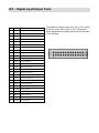
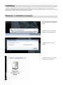
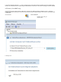
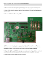
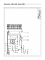
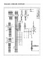
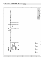
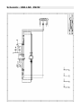
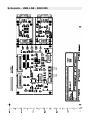
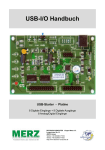
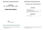
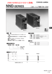
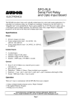
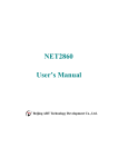
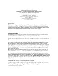
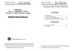
USB-I/O Manual
USB-Starter - Board
8 Digital Input + 8 Digital Output
16 Analog/Digital Input
DECISION-COMPUTER Jürgen Merz e.K.
Lengericher Str. 21
49536 Lienen
Telefon +49 (0)5483-77002
Telefax +49 (0)5483-77003
http://www.decision-computer.de
Data
Product Code:
AUSBSTARTER
USB STARTER
USTART - Board-version
Bus:
USB 2.0
Description:
8 digital input
8 digital output
Each digital I/O provides voltage range from
0V to 3.5V, where 0 to 0.4V is OFF and
2.8V to 3.4V is ON.
Support 8 analog to digital channels
Each analog to digital channels supports
10 bit 0~10V ADC input
Features:
High Speed 8051 μC Core
USB 2.0 Function Controller
Support USB ID 0~14 SET
USB-Bus Power DC+5V 0,5A
Software/Driver:
Windows-XP Vista will use HID-interface and sample for
programming, Linux driver and sample for programming.
Package includes the following items:
USB Starter Board
USB cable
Software and Manual CD
n!
Operating temperature range: 0 ~ 55C.
Relative humidity rage: 0 ~ 90%.
Size: 115 mm x 80 mm x 25 mm
Security Note
This device should not be used in applications where failure may result in death or injury without
proper consideration and design of associated system architecture and redundant safety features.
Connection and repairs are allowed only by a specialist.
When used in a machine or plant, is to ensure that after installation continues to the relevant
provisions, rules and guidelines are complied with!
These products come into contact voltage, therefore to consider the applicable VDE regulations
VDE 0550 / 0551, VDE 0700, VDE 0711, especially VDE 0100 and VDE 0860.
J1 USB Connection USB-B
VCC
+5 VDC (USB VBUS POWER)
D-
Data -
D+
Data +
SGND
Signal Ground
S1 Reset Button
The S1 switch is used to reset 8051, the signal assignments are shown in the following.
Pin
Signals
1
Reset SW+
2
Reset SW-
JP3 - Digital Input/Output Ports
Pin
Signal
Description
SGND
Signal Ground
4
SGND
Signal Ground
5
P0D00
IN Port 0/Line 0
6
P0D01
IN Port 0/Line 1
7
P0D02
IN Port 0/Line 2
8
P0D03
IN Port 0/Line 3
9
P0D04
IN Port 0/Line 4
10
P0D05
IN Port 0/Line 5
11
P0D06
IN Port 0/Line 6
12
P0D07
IN Port 0/Line 7
13
P0D08
OUT Port 1/Line 0
14
P0D09
OUT Port 1/Line 1
15
P0D10
OUT Port 1/Line 2
16
P0D11
OUT Port 1/Line 3
17
P0D12
OUT Port 1/Line 4
18
P0D13
OUT Port 1/Line 5
19
P0D14
OUT Port 1/Line 6
20
P0D15
OUT Port 1/Line 7
21
SGND
Signal Ground
22
SGND
Signal Ground
23
+5V
+5V von der Platine (USB)
24
SGND
Signal Ground
SGND
Signal Ground
1
2
3
25
26
The digital I/O voltage range from 0V to 3.5V, where
0 to 0.4V is OFF and 2.8V to 3.4V is ON and the
signal assignments of digital input/output are shown
in the following.
JP4 Analog/Digital-Input
Pin
Signal
Description
2
SGND
Signal Ground
3
ADIN0
Analog unipolar input channel 0
4
SGND
Signal Ground
5
ADIN1
Analog unipolar input channel 1
6
SGND
Signal Ground
7
ADIN2
Analog unipolar input channel 2
8
SGND
Signal Ground
9
ADIN3
Analog unipolar input channel 3
10
SGND
Signal Ground
11
ADIN4
Analog unipolar input channel 4
12
SGND
Signal Ground
13
ADIN5
Analog unipolar input channel 5
14
SGND
Signal Ground
15
ADIN6
Analog unipolar input channel 6
16
SGND
Signal Ground
17
ADIN7
Analog unipolar input channel 7
18
SGND
Signal Ground
19
+5V
+5V Power
20
SGND
Signal Ground
1
Each analog to digital channels supports 10 bits
0~10V ADC input.
Sample Schematic Output
Sample Schematic Input
Strong electromagnetic sources, such as power lines, large electric motors, switches, or welders can cause strong electromagnetic
interference. Video monitors and cables are strong sources of interference.
If the cable must be led by an area with significant electromagnetic interference, shielded cables with grounding on the source
should be used.
Avoid placing your cable parallel to a high-voltage line! to minimize adverse effects, insert the cable at right angle to the power line.
Installation
The decision-computer USB devices use the HID (human interface device). The HID belongs to the generic device class is
integrated in the operating system. If a new HID device is connected, no driver installation is required. The functions for access and
control of HID hid.dll you can find in the Windows System32 folder.
Windows 7 installation example
2. Connect USB cable. Use USB port
with 500mA power or hub with power
adapter.
3. USB input device - device driver
software is successfully installed
4. USB input device - use now
possible
5. In the Control Panel, you can find
the Decision-USB module now
6. The Device Manager still shows a „!“. Cause is a missing driver for the serial port that is available at the fully equipped version
USB lab. The USB Starter Board is a part-equipped USB LAB Board. Therefore, the driver without existing port must be installed!
VCP driver ( For LABKIT only )
Virtual COM port (VCP) drivers cause the USB device to appear as an additional COM port available to the PC. Application
software can access the USB device in the same way as it would access a standard COM port. This function is only implemented
in USBLABKIT.
32-bit Windows
64-bit Windows
Decision_VCP_driver_32
Vertual_COM
6. Ready to use
SOFTWARE PROGRAMMING UNDER WINDOWS AND LINUX
On Windows, we offer a function library and dll file as programming help. See the manual „USBDII_Manual.pdf“ and demo code in
VB/VC / Delphi on the decision-Studio CD.
We offer a C-source Linux users for direct access to the USB devices. See „Dcihid 0.5.1.tgz“ manual and example.
DIAGNOSTICS UNDER WINDOWS/XP
USB test Program.exe is a diagnostic tool to test USB devices on Windows/XP.
The USB test software can be found on the decision-Studio CD.
The examples and drivers be developed continuously. See the latest on the decision-computer-Merz „Service CD“.
An important way to get more informations you find at http://www.usb-industrial.com
Software support on the short way: http://www.usb-industrial.com/support.html
USB Industrial.com Overview:
Windows Support
2010/04 USBDII.dll
2.0.0.4
Watchdog Timer
This package includes Dynamic-link library which is developed by Decision Computer to communicate with the USB Series Device. It can be
included in multiple computer language (VB6, VC6, VB.NET, C# Delphi)
under Windows.
This watchdog timer is a kind of software timer that triggers a system
reset or other corrective action if the main program, due to some fault
condition. The intention is to bring the system back from the unresponsive state into normal operation. This function is new released and please
contact us to get further information.
VCP driver
( For LABKIT Only )
Virtual COM port (VCP) drivers cause the USB device to appear as
an additional COM port available to the PC. Application software can
access the USB device in the same way as it would access a standard
COM port. This function is only implemented in USBLABKIT
Linux Support
dcihid - 0.5.1
Basic function library
and demo program
2009.05.01
This package includes a c library and a demo program which is developed by Decision Computer to communicate with the USB Series Device
under Linux. It also includes a ReadMe file to demonstrate how to use it
and package‘s format is .tgz.
Firmware Update
Firmware Hex file
Download
This Package includes a driver and a software which is developed by
Decision Computer to update the newest firmware into the USB Series
Device. When new version of firmware is released, user can follow the
instructions to update the firmware.
LabVIEW Support
LabVIEW 8
LabVIEW 2009
This package includes manual and examples which demonstrate how
to connect and develop USB Series Device under LabVIEW,which is a
well-known platform and development environment for a visual programming language from NI.
ProfiLAB Support
Init Value Setting Tool
Data Acquisition and
Remote Monitoring Tool
This package includes manual and examples which demonstrate how
to connect and develop USB Series Device under ProfiLAB, which is a
well-known platform and development environment for a visual programming language from Abacom.
(For Output Channel)
The Init Value Setting Tool is a software tool to set init value for output
channel. User can use this tool to plan output channel as default high or
default low when power on.
The Data Acquisition and Remote Monitoring Tool (DARMT) is a software tool to record high/low state reports at local computer, and transmit
them to FTP site to achieve data acquisition and remote monitoring
USB by LAN or Wireless
The remote control of Decision USB products by LAN or wireless with a remote-PC is very simple with a multi port USB Server
Because no driver should be installed to the installation and programming is very easy.
Under Windows, are the external USB I/O directly in the Device Manager and can be connect or control such as in the original
host PC.
How to update the firmware for USB-STARTER?
1. Remove the external input signal Voltage and only support device power.
2. Use 4 little wires to connect each of two points on S2, just like the demonstration below.
3. Connect PC to the Board by USB
4. When connecting the wires, computer will treat the board as a different
device, it needs to install driver. If this is the first to use this function, please
indicate the driver install path to the Driver Folder to install the driver.
5. Open the Software USBBootloader.exe and press the Open button and indicate the hex file and then press the Download button to update firmware.
6. Disconnect from PC and remove the wires.
Schematic - USB-LAB - Board
You can download the schematics in A4-PDF at:
http://www.decision-computer.de/Download/USB/download-lab.html
Schematic- USB-LAB - Reset-USB
Schematic - USB-LAB - ID-DIO-AD
Schematic - USB-LAB - Powersupply
Schematic - USB-LAB - RS232
Schematic - USB-LAB - R422/485
A.1 Copyright
Copyright DECISION COMPUTER INTERNATIONAL CO., LTD. All rights reserved. No part of
SmartLab software and manual may be produced, transmitted, transcribed, or translated into any
language or computer language, in any form or by any means, electronic, mechanical, magnetic,
optical, chemical, manual, or otherwise, without the prior written permission of DECISION
COMPUTER INTERNATIONAL CO., LTD.
Each piece of SmartLab package permits user to use SmartLab only on a single computer, a
registered user may use he program on a different computer, but may not use the program on
more than one computer at the same time.
Corporate licensing agreements allow duplication and distribution of specific number of copies
within the licensed institution. Duplication of multiple copies is not allowed except through
execution of a licensing agreement. Welcome call for details.
A.2 Warranty Information
SmartLab warrants that for a period of one year from the date of purchase (unless otherwise
specified in the warranty card) that the goods supplied will perform according to the
specifications defined in the user manual. Furthermore that the SmartLab product will be
supplied free from defects in materials and workmanship and be fully functional under normal
usage.
In the event of the failure of a SmartLab product within the specified warranty period,
SmartLab will, at its option, replace or repair the item at no additional charge. This limited
warranty does not cover damage resulting from incorrect use, electrical interference, accident, or
modification of the product.
All goods returned for warranty repair must have the serial number intact. Goods without serial
numbers attached will not be covered by the warranty.
The purchaser must pay transportation costs for goods returned. Repaired goods will be
dispatched at the expense of SmartLab.
To ensure that your SmartLab product is covered by the warranty provisions, it is necessary that
you return the Warranty card.
Under this Limited Warranty, SmartLab’s obligations will be limited to repair or replacement only,
of goods found to be defective a specified above during the warranty period. SmartLab is
not liable to the purchaser for any damages or losses of any kind, through the use of, or inability to
use, the SmartLab product.
SmartLab reserves the right to determine what
constitutes warranty repair
or replacement.
Return Authorization: It is necessary that any returned goods are clearly marked with an RA
number that has been issued by SmartLab. Goods returned without this authorization will not be
attended to.