1
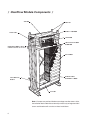
/ ClearFlow Crossflow Application /
®
User Manual
/ Contents /
Note
This manual contains vital information for the proper installation and
operation of your ClearFlow plume control modules. Carefully read the
manual before operation of the ClearFlow equipped tower and follow
all instructions. Save this manual for future reference.
Plume Characteristics ............................................................................ 3
Components ........................................................................................... 6
Specifications ......................................................................................... 7
Installation .............................................................................................. 8
Operation.............................................................................................. 10
Maintenance ......................................................................................... 13
Troubleshooting .................................................................................... 14
The following defined terms are used throughout this manual to bring attention to the presence of hazards of various risk levels, or to important
information concerning the life of the product.
Warning
Indicates presence of a hazard which can cause severe personal
injury, death or substantial property damage if ignored.
Caution
Indicates presence of a hazard which will or can cause personal injury
or property damage if ignored.
Note
2
Indicates special instructions on installation, operation or maintenance
which are important but not related to personal injury hazards.
/ Plume Characteristics /
Because of the evaporation that takes place in a cooling tower, the leaving
airstream is saturated with water vapor. This plume of saturated air can
be highly visible because it is usually warmer, and contains considerably
more moisture, than the surrounding atmospheric air. As it cools to reach
equilibrium with the ambient air, its excess water vapor condenses because
cold air is incapable of assimilating as much moisture (specific humidity)
as warm air. This condensed plume of moisture becomes visible as fog.
The cooling of this plume also decreases its buoyancy—ability to rise. In
many cases, particularly in adverse wind conditions, cooling plumes will
remain at very low levels until they dissipate, often reinforcing ground level
fogging. This is unacceptable in the vicinity of airports, and is of serious
concern when their density and persistency can affect highway visibility.
The density, persistency, and buoyancy of this visible plume is a function
of the total amount of heat extracted from the water (by evaporation), the
temperature at which the heat is extracted, and the temperature of the
ambient atmospheric air. The greater the difference between the temperature of the warm exhaust air—plume—and that of the cool ambient air,
➠
3
/ Plume Characteristics /
the more visible the plume. Visible plumes are typically much more dense
and persistent in the wintertime than they are in the summer season. This
is shown graphically in Figure 1 below, which relates the characteristics
of the plume to the saturation curve of a psychrometric chart.
In winter operation, air enters the tower at condition 1 and leaves saturated
at condition 2. On leaving the tower, the air reaches equilibrium with the
ambient air along line 2–1. In doing so, it remains in the supersaturated
(fog) region of the chart for a considerable time.
TU
R
CU ATIO
RV
N
E
4
SPECIFIC HUMIDITY
SA
SUPER SATURATION
(Fog) AREA
2
MIXING AIR
ABOVE TOWER
3
SUPER HEAT
(Non-Fog) AREA
MIXING AIR
WITHIN TOWER
1
Figure 1
DRY BULB TEMPERATURE
Conversely, summer air enters the tower at condition 3, and exits saturated
at condition 4. Returning to ambient conditions along line 4–3, the leaving
airstream is never within the fog region. This classifies the plume visibility
as wispy and short-lived, often not persisting beyond a few meters above
the fan cylinder. Although higher heat loads can increase the persistency
of summertime plumes, they never reach the density of those that form
in the cooler seasons.
Marley ClearFlow modules provide a means by which the plume leaving
the tower can be made less visible, or more buoyant, or both resulting in
reduced ground fogging. This is done by producing a stream of heated dry
air that is mixed with the tower’s primary saturated airstream prior to its
exit from the tower. This results in desaturation of the plume to the point
4
/ Plume Characteristics /
where it does not cross into the fog region on its way back to ambient
atmospheric air conditions. That is to say, little or no condensation will
be caused to occur.
Visibility reduction is explained graphically in the Figure 2 psychrometric
diagram.
TIO
RV
RA
R
ING
ST MIX FAN
E
ET
OV
W
AB
1 DRY STREAM
CU
TU
SA
4
M
EA
SUPER HEAT
(Non-Fog) AREA
TREAM
2
PLENUM S
SPECIFIC HUMIDITY
Figure 2
SUPER SATURATION
(Fog) AREA
E
N
The primary airstream enters the cooling tower’s wet section (fill) at condition
1, and leaves saturated at condition 2. Meanwhile, a secondary airstream
enters the ClearFlow module at condition 1, gains heat (but no moisture
content), and leaves at condition 3. These two airstreams mix together
3
DRY BULB TEMPERATURE
along line 3–2, exiting the tower at condition 4. Returning to atmospheric
conditions along line 4–1, the plume never (or barely) enters the fog region
and is, therefore, neither dense nor persistent.
Plume characteristics depend upon the application of the ClearFlow modules to the cooling tower. Fewer and smaller modules can increase the
buoyancy of the plume (plume rise), but may not decrease plume visibility
to the degree desired. More or larger modules not only increase plume
buoyancy, but decrease its visibility significantly. In many cases, the plume
can be made to become invisible within one or two fan diameters above
the top of the tower fan cylinder.
5
/ ClearFlow Module Components /
COVER
FRAME
SPRAY HEADER
PIPE INLET
NOZZLES
HEAT EXCHANGER
SLEEVES
DIFFUSION/SEAL TRAY
DEBRIS BASKETS NOT SHOWN
DAMPERS
STRUCTURAL
SUPPORT TUBES
COLLECTION
BASIN
OUTLET
Note—Dampers may not be utilized on some large crossflow towers. Also,
the collection basin and outlet are normally unnecessary on large crossflow
towers and therefore will not exist on those installations
6
/ Specifications /
General
The frame, side panels, front and rear panels, and cross-bracing consist
of pultruded fiberglass channels, panels, and square tubes.
Cover
The spray chamber cover consists of pultruded fiberglass interlocking
panels. It is held in place with stainless steel bolts.
Spray System
Spray header piping is PVC. Nozzles and branch arms are injection-molded
polypropylene. Nozzle and branch arm assemblies are attached to the
header pipe with stainless steel straps.
Diffusion/Seal Trays
The diffusion/seal tray is vacuum formed ABS. Its purpose is to direct the
incoming hot water into the separate heat exchanger sleeves where it will
not come into direct contact with the air.
Heat Exchanger Sleeves
The heat exchanger sleeves are thermoformed .5 mm thick PVC. They
separate the hot water from the air flowing through the ClearFlow module.
They also provide the surface area, and promote the air turbulence necessary to maximize the heat rise of the air flowing through the modules
without increasing its absolute humidity.
Support Tubes
The sleeve support tubes are stainless steel. Four of these tubes—two
top, two bottom—pass through the heat exchanger sleeves to hold them
firmly in their intended position.
Collection basin
The collection basin and outlet are molded FRP.
Damper system
The Dampers, and their linkage, are galvanized steel.
7
/ Installation /
ClearFlow modules are located on the cooling tower such that a portion
of the hot water returning from the process, flows through the ClearFlow
modules before returning to the cooling tower. Meanwhile, the incoming ambient air, induced by the tower’s fan, is divided—through the use
of dampers or doors—between the ClearFlow modules and the normal
wet-section of the cooling tower. In that situation, part of the incoming air
goes only through the ClearFlow modules—and part goes only through
the cooling tower fill. These two airstreams, one heated and dry, the other
heated and saturated with moisture, merge in the plenum chamber below
the fan and mix together. This leaving effluent mixture will have increased
buoyancy and will be sufficiently desaturated to be less visible or in some
cases invisible.
Although ClearFlow modules can be operated year-round, they are usually activated only when they are considered to be needed. The primary
reason why they are not typically used year-round is that operational
modules (dampers open) reduce the amount of air flowing through the
evaporational wet section of the tower. Unless the cooling tower has been
specifically sized for year-round plume abatement, this may cause some
degradation in thermal performance, perhaps at the very time (summer)
when maximum thermal performance is most important to the operation
of your system. In off-season (fall, winter, and spring) operation, the water
temperatures produced by the cooling tower are usually sufficiently cold
to make any performance degradation caused by the use of the modules
unnoticeable.
Figure 3 shows the probable arrangement of the modules for either of
two situations. The modules on the left deliver their air to the tower's fan
plenum area through a two-position air-control door, wherein the doors
are either fully open or fully closed. This arrangement is typical of those
installations where plume abatement is necessary only in the cooler months,
and where control of the cold water temperature is not expected to be of
great concern. On the other hand, the modules on the right have been
fitted with multi-position air-control dampers which allow modulation of
the dry air supply. This arrangement is typical of those installations where
year-round plume abatement may be necessary, and the cooling water
temperature is critical to your process.
8
/ Installation /
PLENUM
CLEARFLOW
MODULE
WATER IN
AIR CONTROL
DAMPERS
AIR CONTROL
DOOR
AIR FLOW
DRY AIR
AIR FLOW
WET AIR
WET SECTION
FILL
AIR FLOW
AIR FLOW
Figure 3
9
/ Operation /
Note
The operating mode of a tower with ClearFlow plume abatement
modules will vary with the need for plume abatement or enhanced
plume buoyancy. Generally speaking, the modules will probably not be
activated during the hottest months of the year, because of the scant
visibility of a normal hot weather plume. During that period, when
plume control is not needed, none of the circulating water should be
directed through the modules—the module air dampers or air-control
doors should be fully closed—and the tower should be operated as
if the ClearFlow modules did not exist.
Module Water Flow
When the weather cools to the point where the plume begins to become
more dense and persistent, and slower to rise, the appropriate portion of
the incoming hot water should be diverted through the ClearFlow modules.
In this mode, a portion of the hot water returning to the tower will flow
through the modules before returning to the auxiliary spray system or to
the tower's cold water basin.
Module Airflow
Once the appropriate water flow has been established through the modules,
plume abatement and buoyancy is established by controlling the flow of
air through the ClearFlow modules.
Note
Do not attempt to control plume characteristics by varying the water
flow through either the tower or the modules.
Zero module airflow = Visible less buoyant plume, but colder water
When the dampers or air-control doors are shut, all of the air being moved
by the fan flows through the cooling tower fill, providing the maximum
evaporative cooling effect (coldest water)—but also creating the most
visible, and least buoyant, plume.
Full module airflow = Invisible or buoyant plume and warmer water
When the dampers or air-control doors are fully open, a significant portion
of the air being delivered by the fan flows through the ClearFlow modules.
This introduces the maximum amount of warm, dry air into the tower's fan
plenum, and achieves the maximum desaturation of the air leaving the
tower—see Figure 2. In this operating mode, least visibility (and maximum
rise) of the plume is achieved—but at the expense of somewhat warmer
cold water from the tower.
10
/ Operation /
Damper Modulation
On installations equipped with air-control dampers, the dampers may be
modulated to achieve the best balance between coldest water temperature
and maximum plume control. Closing the dampers provides colder water.
Opening the dampers provides greater plume control. Generally speaking, it is best to start modulation from a fully closed position, opening the
dampers only as much as is needed for acceptable plume rise or abatement. As the weather grows colder, damper opening will have to increase,
reaching maximum opening on the coldest days of winter.
Wintertime Module Operation
When properly piped and maintained, wintertime operation will not present
a problem for the ClearFlow modules. Unlike coil-type heat exchangers,
ClearFlow modules are gravity-flow, non-pressurized, and self-draining.
Accordingly, their PVC heat exchanger cores will not freeze up even during
shutdown periods in the coldest weather.
However, natural precipitation during freezing weather (snow, sleet, etc.)
may cause ice buildup to occur on the blades and linkages of the air dampers. If allowed to build up unrestricted, this ice will render the dampers
inoperable until such time as a natural rise in atmospheric temperature
melts the ice.
Since the coldest weather will necessitate maximum plume abatement, it
is probable that ice buildup will occur when the module dampers are fully
open. Also, it is very probable that the dampers will not have to be operated
until some time after the weather moderates, and the need for maximum
plume abatement reduces. If the dampers do have to be manipulated,
however, the presence of ice will demand that care be exercised.
Caution
If your dampers are manually operated, resistance in the operating
linkage will tell you if there is too much ice to allow proper operation
of the dampers. Motor-operated dampers, on the other hand, should
be checked for the presence of ice before the motor/actuator is allowed to operate. Otherwise, the dampers or damper linkages may be
damaged. Do not attempt to adjust dampers if excessive ice buildup
is present.
11
/ Operation /
Start-up
Start-up of the cooling tower itself should follow the instructions in the
User Manual supplied with your tower. The start-up steps below assume
that the cooling tower is in full operation, and that the ClearFlow system is
not operating, with water flow off and all air intake dampers closed. ClearFlow units should be turned on well before freezing conditions exist.
1. Open all valves related to the ClearFlow water system, and start the
flow of hot water through the modules. Valves should be opened incrementally to prevent excessive flow from damaging the spray system.
2. Assure yourself that relatively equal water flow is going through all
modules. Clear piping and nozzles as necessary.
3. Open all air-control dampers. When air is flowing equally through all
modules, there should be a noticeable reduction in the density and
persistency of the tower's plume. The cooler the weather, the more
noticeable the change will be.
Plume control
Once the water flow has been established to the ClearFlow modules, it
must not be manipulated as a means of adjustment of the plume abatement function. Only the flow of air through the modules should be subject
to adjustment.
1. If plume abatement and/or plume rise is adequate, but colder water is
required, reduce the proportion of airflow going through the ClearFlow
modules. On air-control damper equipped modules, gradual closure of
the dampers will achieve the desired result.
2. If the airflow through the modules has been reduced and greater plume
abatement or buoyancy is needed, open the air intake doors or dampers
to increase the hot dry air.
Shutdown
1. Fully close all air-control dampers or air-control doors.
2. Shut off the water flow to the ClearFlow system.
3. Close all intake valves related to the ClearFlow system. If a dedicated
pump supplies water to the modules, it is normally sufficient to turn the
pump off without closing the throttling valves. The throttling valves are
then properly set for subsequent operation.
4. If shutdown during freezing weather, drain system to prevent damage.
Warning
When working in the vicinity of the fan, or when working on dampers,
the fan motor should be locked out and remain shut down until the
work is accomplished and the threat of danger is over.
12
/ Maintenance /
Spray system
The spray system is accessed by removing the fiberglass cover on top
of the modules. The nozzles are large diameter and, therefore, not very
susceptible to clogging. When necessary, however, the nozzles can be
removed for cleaning.
Note
It is important to keep the module cover securely installed during
ClearFlow operation. This prevents air from migrating into the water
passages.
Diffusion/Seal tray
The diffusion/seal trays are covered by plastic mesh baskets designed to
collect any Amertap balls, pipe scale, or other debris that passes through
the spray system. These debris baskets should be inspected and emptied as often as experience proves it to be necessary. This can vary from
location to location.
Heat Exchanger Sleeves
During routine cooling tower inspections, the modules should be inspected
to see if airborne debris (dirt, leaves, etc.) has built up on the outside of the
heat exchanger sleeves. Such debris will adversely affect the module's heat
transfer capability and should be removed. If water hoses are used, they
should be of relatively low pressure to prevent damage to the sleeves.
Air-Control Dampers
Under “Wintertime Module Operation”— page 11—the possibility of
natural ice buildup is discussed. Do not attempt to operate dampers if
excessive ice buildup is present. Torque limits usually can be set on electric
operators—manual operators will require operator judgement of excessive
force. Typical operation should not require damper adjustment under icing
conditions. The dampers should be kept free of debris as discussed in
“Heat Exchanger Sleeves” above.
The bearings used in the air-control dampers require no lubrication.
Air-Control Doors
Air-control doors should be inspected each year prior to the beginning of
plume abatement “season” to make sure thy are operable.
13
/ Troubleshooting /
Trouble
Cause
Remedy
Plume is too visible, or
rises sluggishly.
Water is not flowing to modules.
Open all valves in ClearFlow water system and start water flow.
Check to see that equal water flow is going through all
modules.
Open all module dampers by an equal amount until desired
plume control is achieved.
See causes and remedies below.
Dampers are closed, or are not
sufficiently open.
Water to modules is flowing down the
outside of the heat exchanger sleeves.
Water is splashing out of plume
abatement modules.
Atmospheric condition is more difficult
Water to modules is
flowing down the outside
of the heat exchanger
sleeves.
than that for which the ClearFlow
application was designed.
Debris baskets are clogged.
Water flow to module is excessive,
causing overflow of the diffusion tray.
Diffusion tray is out of place.
Heat exchanger sleeves are out of place.
Heat exchanger sleeves are leaking.
Water is splashing out
of plume abatement
modules.
Module spray system is clogged.
Water flow to module is excessive,
causing overflow of the diffusion tray.
Diffusion tray is out of place.
Heat exchanger sleeves are out of place.
Cold water temperature is Cooling tower fans are not running at full
too warm.
speed.
Dampers are open at the wrong time—or
are open too far—causing air to bypass
the fill.
Something is wrong with the cooling
tower—or it is being operated improperly.
14
See causes and remedies below.
Open dampers as wide as they will go, and accept the amount
of plume control produced.
Remove spray chamber cover and empty debris baskets.
Spray system of one or more modules may be clogged.
Remove clogged nozzle and clear out debris.
Balance water flow to all modules. If water flow is still excessive,
throttle the flow to the modules.
Reinstall diffusion tray correctly.
Make sure that all structural support tubes are socketed in the
side panels. Arrange heat exchanger sleeves such that the
discharge slots in the diffusion tray discharge the water into the
sleeves.
Seal leaks in the PVC sleeves. Consult your Marley sales
representative for technical assistance
Remove and clean out the nozzle and branch arm assemblies.
Balance water flow to all modules. If water flow is still excessive,
throttle the flow of the auxiliary pump.
Reinstall diffusion tray correctly.
Make sure that all structural support tubes are socketed in the
side panels. Arrange heat exchanger sleeves such that the
discharge slots in the diffusion tray discharge the water into the
sleeves.
Switch fans to full speed operation.
Dampers should be completely closed if no water is flowing
through the modules. If water is flowing through the modules,
the dampers should only be open far enough to accomplish
plume control. Further opening merely diverts air from the fill
unnecessarily. Refer to your operating curves in your User
Manual.
Follow operating and maintenance procedures outlined in your
cooling tower User Manual.
15
������������������������������������������������������������������������������������������������������������������������
��������������������������������������������������������������������������������������������������������������������
����������������������������������������������������������
Manual 99-1427