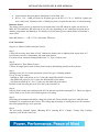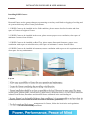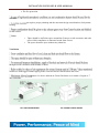
1
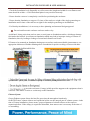
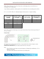
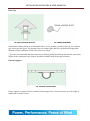
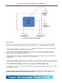
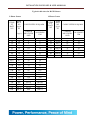
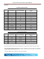
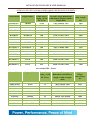
INSTALLATION GUIDELINES & USER MANNUAL OVERALL SPECIFICATIONS OF KIRLOSKAR GREEN SILENT GENSETS Liquid Cooled KGPI- Genset Genset Model Engine Model Prime Power rating at 0.8 PF (kVA) Overall Canopy Dimensions with silencer length x width x height (mm) Approx. Weight (with Canopy) KG KG30WS-5 KG40WS-1 KG50WS KG82.5WS-2 KG82.5WS-2 KG100WS KG125WS-3 KG160WS-2 KG160WS-2 KG160WS KG250WS-1 KG250WS-1 KG250WS-1 KG320WS-3 KG400WS-2 KG500WS-3 KG600WS-3 KG600WS-3 3R1040 4R1040 4R1190 4R1040T 4R1040TA 4K1080TA 6R1080TA 6K1080TA 6K1080TA 6SL9088TA 6SL1500TA – I 6SL1500TA – II 6SL8800TA DV8-I DV8 DV10 DV12 DV12 25/30 40/45 50 62.5 82.5 100 125 140 160 160 180 200 250 320 400 500 600 625 2355 X1090 X 1915 2655X 1210X 2410 3100X1270X2100 3210X 1110 X 2590 3210X 1110 X 2590 3210 X 1305 X 2670 3450 X 1300 X 2480 4015X 1505 X 2670 4015X 1505 X 2670 4350 X 1850 X 2050 4555 X 1890X 2800 4555 X 1890X 2800 4555 X 1890X 2800 5700 X 2120 X 3445 5700 X 2120 X 3445 6200 X 2120 X 3440 6660 X 2120 X 3598 6660 X 2120 X 3598 1260 1520 1500 1930 1950 2500 2700 2500 2600 3720 3870 3950 4660 6000 6000 6655 7500 7500 Air-cooled KGPI - Genset Genset Model Engine Model Prime Power rating at 0.8 PF (kVA) SEKG6AS7 SEKG10AS5 SEKG10AS5 KG15AS1-C KG25AS-C KG35AS KG35AS KG40AS KG50AS KG70AS EA10 EA16 EA16 HA294 HA394 HA494 HA494 HA494TC HA694 HA694TC 5 7.5 10 15 25 30 35 45 55 70 Overall Canopy Dimensions with silencer length x width x height (mm) 1610 X 825 X 1930 2035 X 825X 1930 2035 X 825X 1930 1750 X 1215 X 2235 1997 X 1185 X 1818 2805 X 1225 X 1940 2805 X 1225 X1940 2805 X 1225 X1940 3450 X 1320 X 1900 3450 X 1320 X 1900 Approx. Weight (with Canopy) KG 650 850 850 1220 1350 1440 1440 1580 1870 1920 INSTALLATION GUIDELINES & USER MANNUAL Note : are subject to change without prior notice. Also refer to latest product catalogue for updates. r than standard operating conditions, consult Seller or Kirloskar’s Area Office. Sizing of KGPI Genset To select the right generating set under a given set of circumstances, knowledge of generating set and its performance under various conditions is necessary. It is also equally necessary to understand load characteristics and to make a load analysis. Beyond that, the effect of the voltage regulation systems plays an important role. It is better to select a slightly larger generator capacity than the available load; the reason is that additional uses are invariably observed after it has been installed. These are usually not predictable. By having a margin available it is possible to power some loads which may have been overlooked during Genset selection, or which may be added after the installation of the Genset. Ratings The rating of an alternator is expressed either in kilowatt (kW) or kVA. The relation between kW and kVA rating is kW = kVA x Power Factor kW = 1.732 x V x A x Power Factor (for 3 phase alternator) / 1000 kW = V x A x Power Factor (for a single phase alternator) / 1000 Where V = Line voltage; A = Line current Load variation between phases should not be more than 10% and min 50% load should be available at the time of commissioning. Power Factor The power factor of electrical system depends upon the nature of characteristics of load e.g Induction motors, Furnaces, thyristor, power electronics etc. Power Factor is lagging for inductive load. Power Factor is leading for capacitive load. Power factor is unity for purely resistive loads. Normally, a generator is designed for a power factor of 0.8 The table below gives power factors of non-motor loads. Type of load Incandescent lights Heating elements, ovens Fluorescent lights Induction furnaces Arc furnaces Welding Set Transformer) Welding Set (AC Motor-DC Generator) Transformers Power Factor 1.00 1.00 0.90 0.60 - 0.70 0.80 - 0.90 0.60 0.80 - 0.90 0.80-0.95 INSTALLATION GUIDELINES & USER MANNUAL Load variation between phases should not be more than 10%. KVA x 1.39 = AMP per Phase for III phase gen set & KVA X 1.39 x 3 AMP for I phase gen set at 100% load . Minimum 50% of AMPs per phase is required at the time of commissioning. Deration Factor The engine’s horse power as mentioned on its name plate is the HP which an engine can deliver in MSL at NTP conditions. HP delivered at site will vary depending on site conditions (deration due to altitude, temperature and humidity). For details of site derations please consult Seller or Kirloskar’s Area Office. Input HP (Metric ) = . kW / 0.736 x Alternator Efficiency Load Calculation Steps to be followed while sizing the Genset. Step 1: Collect all necessary basic data of load. Tabulate the details such as lighting load, motor load, A/C load, Heaters load etc with quantity and name plate details. For motor loads, mention starting method also, i.e. Type of starter used. Step 2 : (Applicable For Three Phase Genset) Convert all single phase loads to three phase loads by distributing equally on three phases. Step 3: Starting power (kVA) of each equipment is based on type of starting method. For eg, In case of motors, - Starting by DOL will pull up to 6 to 7 times the rated full load kW of a motor. - Star/Delta will pull up to 2 to 3 times the full load kW of the motor. - Soft Start will pull up to 1.2 to 1.5 times the full load kW of the motor. Rectifier loads may also pull up to 50% above their rated KVA. Step 4: Sum up all the steady state running loads in kVA and sum up all the starting kVA’s. These two figures will be used to size up the Genset and sequence of loading. Step 5: Determine the maximum allowable voltage dip which the Genset should experience when the total starting KVA is applied on this Genset. This voltage dip percentage is usually known to the customer based on equipment type to be powered. Step 6: The previously obtained figures (Running KVA, Starting KVA, Voltage, Voltage Dip, Loading sequence) will decide Genset size. INSTALLATION GUIDELINES & USER MANNUAL Installing KGPI Genset: Location Dust and Fumes are the greatest danger to generating set as they could lead to clogging of cooling and air system which may affect Genset performance. 1. If KGPI Genset to be installed in free field condition, please ensure dust free location and clear space of 2 times of height of Genset. 2. If KGPI Genset to be installed in the room, please ensure proper cross ventilation, clear space of minimum 3 meters from all sides. 3. If KGPI Genset to be installed on Roof Top, please ensure Structural clearance, proper cross ventilation with respect to wind direction, clear space of minimum 3 meters from all sides. 4. If KGPI Genset to be installed in basement, ensure ventilation with respect to Air requirement and clear space for easy maintenance. Layout crusher plant, garment plant, cement factory, paint factory, chemical factory, etc. the Genset should be isolated from the dust, hazardous and chemical fumes contained in the surrounding air. cleaners (Please contact Seller or KOEL Area office for further guidelines). arrangement for Genset, follow the local rules and regulations. o The environment protections INSTALLATION GUIDELINES & USER MANNUAL o The fire protection alternator. on requires proper planning and the structural design considerations for dynamic loading. for hot surface. Noise o There should be sufficient space around the Genset to avoid resonance and echo effect which contributes to abnormal sound from Genset. o The space should be open without any obstacles. Ventilation through forced ventilation with suitable air ducts. in table are with lagged exhaust piping in the room and silencer fitted outside the room. erature rise above ambient in Genset Enclosure at air intake of engine is 7 deg centigrade. FIG. AIR COOLED GENSET FIG. WATER COOLED GENSET INSTALLATION GUIDELINES & USER MANNUAL Foundation Foundation is one of the important factor affecting the successful operation and life of a generating set. Improper foundation may result in alignment and vibration problems which may subsequently lead to pre-mature failure of Genset Components and Safety. The basic functions of foundation are as below, - To provide leveled platform to seat and seal the Genset. - To support the weight of the entire generating set. - Support the dynamic load of Genset while in running. - Absorb the vibration produced by the rotating and reciprocating masses. - Isolate the surrounding structures by absorbing the vibration of generating set while in running. FIG. FOUNDATION OF GENSET FIG. CORRECT & INCORRECT FOUNDATION While casting the concrete foundation, the bearing strength of the soil at site of installation should be determined. The Table below gives the approximate safe bearing capacity of various soil. Nature of the load bearing material Safe bearing capacity kg/sq. meter Hard Rock Granite Medium Rock Shell Hard Pan Soft Rock Hard Clay Gravel and Corse Sand Loose, Medium coarse and Compact fine sand Medium Clay Loose Fine Sand Soft Clay 2,44,100 – 9,76,400 97,600 – 1,46,400 78,100 – 97,600 48,800 – 58,600 39,000 – 48,800 39,000 – 48,800 29,300 – 39,000 19,500 – 39,000 9,750 – 39,500 9,750 The length and width of foundation should be at least 300 mm more on each side than acoustic enclosure length and width respectively. - It is recommended to have foundation height of 150 to 200 mm above ground level to maintain cleanliness and avoid flooding. INSTALLATION GUIDELINES & USER MANNUAL - Check the foundation level diagonally as well as across the length and width for even flatness and same should be within + 0.50 in horizontal plane in any one direction only. - Ensure that the concrete is completely cured before positioning the enclosure. - Ensure that the foundation to support 1.5 times of the total wet weight of the single generating set installation and 2 times of the total wet weight for the multiple generating set installations. - For Rooftop installations, it is necessary to have planning and structural design approval. Do not install acoustic enclosure on loose sand or clay. Avoid hard / sharp projections such as stone or steel parts on foundation surface, which may damage fuel tank at the bottom. Avoid uneven foundation which may lead to improper resting of Genset on foundation, there by leading to leakage of sound and vibration on Genset. If Genset to be mounted on foundation having uneven surface under unavoidable circumstances, use appropriate thickness of Rubber Matting above foundation for positive sealing of Genset with base. All the Gensets are provided with suitable lifting arrangements. spreader bar / spacer plate, of suitable capacity to avoid any damage of the D G set. e acoustic enclosure (Canopy) which provides support to the equipment when it is moved. This makes it easier to set them up on the foundation. Exhaust System Genset Exhaust system directs the hot flue gases into the atmosphere harmlessly. On KGPI Genset, exhaust silencer and expansion bellow are the integral part of exhaust system. At the time of Genset installation, please ensure, proper alignment of exhaust silencer with respect to expansion bellow. If the canopy is required to dismantle, then utmost care is necessary at the time of re-assembling. INSTALLATION GUIDELINES & USER MANNUAL While taking exhaust gases away from Genset above stack height, please refer table below for selecting the size of exhaust pipe. As per Statutory regulations, exhaust pipe has to be extended above the surrounding stack as below. H = h + 0.2 x vKVA Where H = Minimum height of exhaust stack, h = height of building ENGINE MODEL (WATER COOLED) MINIMUM PIPE INSIDE DIAMETER IN INCH EW-SERIES RB-SERIES 2R/3R/4R 4RTA 4K/6K 6SL K DV 2.5" 2.5" 2.5" 3" 4" 5" 5" 5" ENGINE MODEL (AIR COOLED) MINIMUM PIPE INSIDE DIAMETER IN INCH EA 10/16 HA294/ 394/494 HA694 2" 2.5" 3" Note : If the extension of exhaust pipe is more than 5 meters above Genset, increase pipe dia by 0.5” for every 3 meters. Exhaust bend M S Bends used in exhaust piping should have a long smooth bend as shown in figure to ensure smooth flow of exhaust gases. Exhaust Outlet should have 30® cut at the tail end with Coarse wire mesh. Note : - If No of bends are more than 4, increase the diameter of Exhaust Pipe and Bend by 0.5” for addition of each bend. - The exhaust outlet should be in the direction of prevailing wind. INSTALLATION GUIDELINES & USER MANNUAL Rain Cap FIG. RAIN CAP WITH RAIN CAP FIG. CORASE WIREMESH If horizontal exhaust outlet as recommended above is not possible, provide a rain cap over exhaust pipe end as per the figure. The distance between exhaust pipe and rain cap should be higher than diameter of pipe (minimum 2.5D) with coarse wire mesh. t is also recommended that horizontal run of exhaust piping should slope downwards away from engine to the condensate trap. Silencer should be installed with drain plug at bottom. Exhaust Support FIG. EXHAUSE PIPE SUPPORT Proper support is required for the extended exhaust pipe above Genset to ensure no self weight is transferred on to the Genset. INSTALLATION GUIDELINES & USER MANNUAL Type of Exhaust Pipe Use black MS Pipe, Galvanised Iron Pipes should not be used. FIG. CORRECT & INCORRECT EXHAUST PIPE Exhaust Pipes should be joined through flanges. Exhaust pipe throughout should be cladded by mineral wool with aluminium sheet. Minimum thickness of cladding should be 50 mm. Cooling System Liquid Cooled Engine Kirloskar Liquid Cooled Engines use solid cooling system for removal of heat generated in the engine due to internal combustion and to maintain optimum operating temperature for efficient engine operation. KGPI Genset – Liquid Cooled are delivered with initial fill of Pre-mixed Coolant “K-Cool Super Plus”. INSTALLATION GUIDELINES & USER MANNUAL Ensure NO addition of Water in Coolant. -Cool Super Plus” coolant. Air Cooled Engine Kirloskar Air Cooled Engines use Air as a cooling media for removal of heat generated in the engine through cooling passages and to maintain optimum operating temperature for efficient engine operation. Lub Oil System Kirloskar engines utilize the pressure lubrication system with the lub oil filter adequately designed to handle the flow of lubricating oil at the designed pressure and temperature for Lubrication, Cooling and Cleaning of internal components. KGPI Gensets are delivered with initial fill of Lub Oil “K-Oil Super Plus”. -Oil Super Plus” only. K-Oil Super SAE 15W 40 is a specially blended engine oil which ensures: -ups. Use of the wrong grade of oil could lead to : - Overheating of the engine. - Sluggish performance. - Excessive Fuel Consumption - Increase Wear of Bearings and Other moving components. INSTALLATION GUIDELINES & USER MANNUAL Fuel System The fuel (High Speed Diesel) should comply with the following International Standards. DIN 51601 IS : 1460 1995 ASTM D 975-81 : 1D & 2D - Ensure fuel filling point is accessible and clean all the time. - Ensure all fuel piping is leak free. - Avoid fuel spillage. - Ensure fuel dilution does not occur. - Care should be taken while filling of tank to prevent ingress of dust & moisture inside diesel tank. - It is recommended to fill fuel after stopping of the Genset to avoid condensation. It is recommended not to fill Fuel during running of Genset. Electrical System Earthing Any leakages in current will be earthed through the shortest route in the link. KGPI Genset should be connected to earth in accordance to local regulations. The size of the link used for the main earth connection should be of adequate size as shown below table. The generating set and all associated equipment must be earthed before the set is put into operation. 4 numbers of earth pits are required as per Indian Electricity rules / local electricity regulations. - 2 earthing pits for Genset / control panel body - 2 earthing pits for neutral. Resistance between 2 earth pits should be more than 5 Ω. EARTHING WIRE & STRIP SIZE KVA Recommended Earth Strip/ Cable 5 -82.5 KVA 8SWG-COPPER / 25 x 3mm GI 100-250 KVA 25 X 3mm COPPER / 25 X 6mm GI 320 – 625 KVA 50 X 6mm COPPER INSTALLATION GUIDELINES & USER MANNUAL FIG. EARTH PIT INSTALLATION GUIDELINES & USER MANNUAL FIG. 4 NOS EARTHING ARRANGEMENT Power Cable Cabling from Alternator to Panel should be done with proper size of cable and lugs. Typical cable sizes are provided in the tables which are indicative. Please refer to cable manufactures for details. eating and burning of the cable and terminals. terminal box and control panel terminations. les at both the ends of Alternator and Control Panel. of control and monitoring cables should be sheathed and should be within 5 meters length for accurate performance. provided from the ground separately through cable tray. INSTALLATION GUIDELINES & USER MANNUAL Typical cable sizes for KGPI Genset 3-Phase Genset GENS ET RATI NG 5 10 15 20 25 30 40 45 50 62.5 82.5 100 125 140 160 180 200 250 320 400 500 625 1-Phase Genset AMP RATI NG @0.8 PF CABLE SIZES IN SQ MM (App.) COPPER MULTISTR AND ALLUMINI UM 7 14 21 28 35 42 56 63 70 87 115 139 174 195 223 250 278 348 445 556 695.62 869.52 4 4 4 6 10 10 16 16 25 35 50 70 95 95 120 120 150 150 120+95 150+150 185 x2 400 6 6 6 10 16 16 25 25 35 50 70 95 150 185 240 240 300 300 240+185 300+300 240 x 3 300 x 3 GENS ET RATI NG 5 10 15 20 25 30 40 50 AMP RATI NG @0.8 PF 20.83 41.66 62.5 83.33 104.16 125 166.66 208.33 CABLE SIZES IN SQ MM COPPER MULTISTR AND ALLUMINI UM 6 10 16 35 35 50 70 95 10 16 25 50 50 70 95 150 INSTALLATION GUIDELINES & USER MANNUAL BATTERY WATER COOLED GENSET SL. NO. KVA RATING ENGINE MODEL BATTERY RATING IN AMPS. 1 2 3 4 5 6 7 8 9 10 11 12 13 14 15 5,6 7.5/10 20 25 30 45 50 62.5 75/82.5 100/125 125 140/160 180/200/250 275/320/400 500/600/625 EA10 EA16 2R 3R 3R 4R 4R 4RT 4RTA 4K 6RTA 6K 6SL DV DV 88 88 88 88 88 88 120 135 135 135 180 180 180x2 180x2 180x2 AIR COOLED GENSET SL. NO. KVA RATING ENGINE MODEL BATTERY RATING IN AMPS. 1 2 3 4 5 6 12.5/15 20/25 30/35 40/45 50/55 63/70 HA294 HA394 HA494 HA494TC HA694 HA694TC 88 88 120 120 180 180 Ensure that the polarity of the battery connections are correct before switching on the DC controls. charged or replaced and then try to start. INSTALLATION GUIDELINES & USER MANNUAL Before Starting the New KGPI Genset -belt tension as per specifications. Lubrication : - Check Lub oil level with help of Dipstick and if require Topup up to H-Mark with “K-Oil Super”. Fuel : - Ensure fuel tank is clean from inside. - Fill fuel tank with clean High Speed Diesel. - Bleed the fuel system as shown in maintenance manual. Cooling : Liquid cooled engine. - Check Coolant level inside Radiator and Compensatory tank. If required Topup with “K-Cool Super Plus”. Air Cooled Enignes. - Check Blower Fan belt tension. - Check hot air exhaust fan is working properly. Electrical: - Check Battery Polarity. - Check Battery cables are correctly connected and secured. - Check all other electrical connections and intactness. - Ensure Emergency Push Button in released condition. - Ensure Load Change over Switch / Breaker in off condition. Starting and Stopping of KGPI Genset Procedure: Starting KGPI Genset Before Starting - Clean the Genset with dry cloth. - Check the lub oil, coolant and fuel levels – Top up if required as per recommendation given. - Check for V-belt, Hoses and external leakage if any. - Ensure Load change over switch / Breaker in Off condition. INSTALLATION GUIDELINES & USER MANNUAL Starting - For Key Starting Do not crank engine for more than 5 second. As soon as engine fires, release the start key. Leave ignition switch in “ON” position. - For Push Button Starting Gently press starts button once and release. - If engine fails to start, wait for a minute and try again. - Check for leakages if any. - Allow the engine to idle for 3 minutes and then start loading the Genset gradually in steps. - Check for Engine parameters like Oil Pressure, Coolant Temp and Battery charging rate at regular intervals while the Genset in operation and maintain log book. - Check for Exhaust Smoke. - Check for Abnormal Noise if any. - Check for A C Alternator parameters like Voltage, Ampere, KW, PF on all phases. - Ensure load is balanced in all phases as per recommendation and within rated output of Genset. - Check for all gauges and meters provided in Control Panel are working. Procedure: Stopping KGPI Genset Before Stopping - Remove the load from Genset and let it run for about 3 minutes. - For Key Start Put Ignition key in “Off” condition. - For Push Button Start Push Stop button gently once and release. After Stopping - Put Load Change Over Switch in “OFF” position. - Check for leakages if any. - Top Up the Fuel Tank. - Ensure Proper closing of Genset Enclosure. Maintenance Tips First oil change @ 50 hrs or 3 months of commissioning. For details refer user manual. Cleaning and Preservation of KGPI Genset Remove dust deposit from the Cylinder heads, Liners fins, lub oil cooler fins, Radiator and A C Alternator with compressed air. Cleaning with diesel fuel or kerosene may cause dust to deposit again on the cleaned parts. Open the Air duct while cleaning of Air Cooled Engine. Cleaning should be done from the opposite side of the system air flow. INSTALLATION GUIDELINES & USER MANNUAL When deposits are hard, scrape and clean with a water jet. Run the engine after such cleaning till all the water evaporates. When the Genset is kept idle for more than 6 months, it is advisable to protect it from atmospheric moisture, condensates, internal corrosions and rodents Recommended Preservatives: Manufacturer Engine lub oil and Fuel system Engine cooling system for liquid cooled Unpainted ferrous metal parts Bharat petroleum Bharat Preserve oil 30 Bharat Rustrol 152 Hindustan petroleum Autoprun T120 Indian oil corporation Servo Preserve 30 OR Servo 'Run-N' Oil 30 - Bharat Sherol B Emulsion with water ratio 1:20 Koolkit 40.5%Emulsion with water Servo Cut S 20% Emulsion with water - Russtilo DW 904 OR DW901 Veedol Rustop IT Castrol India Veedol tide water oil co. Veedol 30/40 Veedol Amulkut 4 Emulsion with water in ratio 1:15 Rustop 274 Servo RP 125 Alternatively 'Surprabha VCL 302' of Suprabha products can be used in engine cooling System. For preservation and re-commissioning contact seller. After Sales Service Guidelines - The after sales service to KGPI Genset is provided through KOEL’s Country-wide network of authorized spare and service dealers. For information about KOEL’s Authorized Dealers, please contact either the supplier of KGPI Genset or nearest KOEL Area office. - Before commissioning the KGPI Genset, please go through the contents of the warranty booklet. YOU ARE ENTITLED TO RECEIVE THE FOLLOWING ENGINE RELATED DOCUMENTS FROM KGPI GENSET SUPPLIER. - Warranty Booklet - User manual- Hard copy/ Soft copy - Maintenance manual- Hard copy/ Soft copy