1
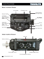
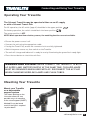
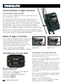
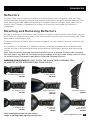
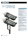
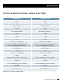
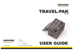
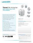
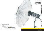
USER GUIDE
Table of Contents
Description
Page
Introduction & Safety Notes
3
Control Panel Guide
4
Connecting and Using Your Travelite
5
Flash Power Control
6
Modeling Lamp Controls
6
Ready Indication
6
Synchronization
7
Changing the Modeling Lamp
7
Changing the Fuse
7
Changing the Flash Tube
7
Travelite Accessories
Mounting and Removing Reflectors
Specifications
2 calumetphoto.com
8–9
9
10 – 11
Introduction
Dear Valued Customer,
Thank you for choosing the Calumet Travelite professional flash system. Accurate, ergonomic,
powerful and simple to use, the Travelite was designed by working closely with photographers to
develop a flash that meets the high standards demanded in professional studios today.
All ‘S-Type’ accessories from the Calumet/Bowens range can be used with the Travelite. For
details of all related products, please call 1-800-CALUMET (225-8638), contact your local Calumet
retail center or visit calumetphoto.com.
In order to obtain the full benefit from your purchase, please take a few moments to familiarize
yourself with this user manual.
Thank you,
Calumet Photographic
Safety Notes
ALWAYS
DO NOT’S
• Always switch power off and disconnect from
the supply before changing modeling bulb or
flash tube.
• Do not use in an environment where moisture
or flammable vapor is likely to come in contact
with the unit.
• Always disconnect the supply before changing
the fuse. Never replace with a fuse of a
different rating.
A spare fuse is fitted in the fuse holder under
the AC inlet (see page 4).
• Do not plug your Travelite into an AC supply
and a Travel-Pak battery at the same time.
• Always exercise care when handling
equipment that has been in use. The reflector
and front end of the unit can become Very Hot.
• Always avoid placing cables where they can be
tripped over. Protect from heavy, sharp or hot
objects, which may cause damage and replace
damaged cables immediately.
• Do not restrict air vents while in use.
• Do not use a unit with damaged housing,
moldings, flash tube or modeling lamp. If the
unit is dropped or damaged in any way, always
have it checked out before using.
• Do not operate the unit without a safe
grounded AC supply.
• Due to the high voltage / high energy used in
Travelites, all servicing must be carried out by
a Calumet-authorized service center.
• Always remove the power cord by gripping the
plug. NEVER pull the cord.
• Always ensure that any extension cord used
has a suitable current rating to prevent
overheating and never use coiled extension
cords.
• Always remove the flash head covers before
using.
calumetphoto.com 3
Control Panel Guide
Rear Control Panel
Carry handle
RF Module Cover
Plug-in Antenna
(Sold Separately)
Photocell On/Off
Lamp Mode
Top - Intermittent
Middle - Continuous
Bottom - Off
AC / Battery
Power Select
Lamp Level
Top - Proportional
Middle - Full
Bottom - User Set
AC Inlet
Fuse
(and Spare Fuse)
Sync Socket
Battery Power Inlet
Side Control Panel
Photocell
Reflector Release
Flash Power Control
Modeling Lamp Control
Flash-Ready/Open-flashTest
4 calumetphoto.com
Connecting and Using Your Travelite
Operating Your Travelite
The Calumet Travelite may be operated either on an AC supply
or with a Calumet Travel-Pak
For AC operation, the AC switch (page 4) should be in the upper position
For battery operation, the switch should be in the lower position
.
.
The center position is OFF.
NOTE: When operated from a battery source, the modeling functions are not available.
• Ensure the power source is off.
• Connect the unit using the appropriate cable.
• If using the Travel-Pak, ensure the connector locks are fully tightened.
• Switch the power source on, then switch on the Travelite.
• The unit will charge and indicate it is ready for use by illuminating the green flash-ready light.
• Press the test button to check the unit fires.
WARNING HIGH VOLTAGE! NEVER CONNECT THE TRAVELITE TO BOTH
AC SUPPLY AND BATTERY SUPPLY AT THE SAME TIME. THIS APPLIANCE
MUST BE GROUNDED WHEN USED WITH AC. DISCONNECT THE AC PLUG
WHEN CHANGING MODELING LAMPS AND FLASH TUBES.
Mounting Your Travelite
Mount your Travelite
on a dependable
support system
The mount bushing on the
L-bracket allows for two
possible ways of mounting
to the stand/support (RIGHT).
Method B may be found
useful if the light is required
to point down.
A
B
calumetphoto.com 5
Flash Power Control
The flash power control output level is variable over 5-stops, from full to 1/32 power. The maximum
power available depends upon the model (See specification table) and is denoted by the numbers 1-6
on the side control panel. The power settings are denoted in 1⁄5-stops. The numeric divisions
indicate full-stop divisions.
When switched on from either AC or battery supply, the unit will charge. Once the unit has charged
to the desired power level, the green flash-ready lamp will illuminate indicating that the unit is ready
to fire.
Note: If the unit is subjected to rapid operation over extended periods, it may automatically go into
an overheat condition. In this condition, the flash-ready lamp will blink to indicate overheat and
modeling functions will be disabled in order to allow the unit to cool. The unit will automatically
resume operation once cooled sufficiently.
In an overheat condition, the unit will typically take 20 minutes to cool down. By switching the unit off
and then on again after approximately 10 minutes, the unit can be re-activated in order to get a few
extra shots if needed.
Modeling Lamp Controls
The modeling lamp control output level is variable over 5-stops, from full to 1/32 power. The
modeling lamp control dial is denoted by the numbers 1-6 on the side control panel. The power
settings are denoted in 1⁄5-stops. The numeric divisions indicate full-stop divisions.
The 3-position lamp mode control switch on the rear panel controls the following functions;
Top (Intermittent) - Lamp goes out when unit is flashed and comes back on when the unit is ready.
Middle (Continuous) - Lamp stays illuminated regardless of ready state.
Bottom (Off) - Lamp is off.
The 3-position lamp level control switch on the rear panel controls the following functions;
Top (Proportional) - Lamp level varies proportionately to the flash power control dial.
Middle (Full) - Lamp level is maximum regardless of modeling lamp control dial settings.
Bottom (User Set) - Lamp level varies with the modeling lamp control dial.
Note: The modeling lamp also has a “lamp saver” function that will switch off the modeling lamp
after 30 minutes if no adjustment or flashing of the unit is carried out.
Ready Indication
The illuminated open-flash test button on the side of the unit shows the charge state as follows;
Power down - LED off (Battery mode only when charger has powered down).
Charging - LED flashes quickly.
Ready - LED lit continuously.
Dumping - LED flashes slowly.
6 calumetphoto.com
Synchronization
There are several ways to trigger your Travelite
Open Flash:
For testing or multiple-flash applications the open-flash button can be used.
Sync Socket:
The standard 1⁄4" socket on the rear panel of the unit may be used for direct connection to a camera
set to 'X' synchronization. Two Travelites may be connected together using a 'Y' connector. An
Infrared receiver or flash slave may also be plugged into this socket. The socket operates at +5V and
is safe for use on digital cameras.
Built-in Photocell:
The Travelite has a built-in switchable photocell enabling the unit to be triggered by the flash from
any other flash unit or a small camera mounted flash gun. It is mounted behind the red transparent
cover on the top of the unit. The photocell on/off switch is located on the rear control panel.
Radio Frequency (RF) Card Module:
The Travelite unit can be triggered wirelessly by purchasing and installing either a Calumet LiteLink
Radio Trigger Card Kit (CE1561) or Calumet Radio Card Kit for PocketWizard® (CE1563) and using
their respective trigger unit. Kits include one radio trigger card and one plug-in antenna.
Changing the Modeling Lamp
Switch off Travelite and disconnect from the power supply. Allow lamp to cool before removing.
Unscrew modeling lamp from lampholder in the center of the reflector and replace with new lamp.
Note: It is recommended that a Photoflood or Halostar bulb with a maximum wattage of 275 watts
is used. The manufacturer will not accept liability on the use of any lamp with a greater wattage
than 275.
Changing the Fuse
The modeling and flash circuitry is protected by a single 10-amp fuse mounted on the rear panel.
Never replace the fuse with one of a different rating. As the fuse may blow when the modeling lamp
fails, always check the fuse when replacing the bulb. A spare fuse is supplied in the fuse holder.
Always switch the unit off and disconnect the Travelite unit from the power supply before changing
the fuse.
Changing the Flash Tube
Ensure that the unit is switched off and disconnected from the AC
supply and then wait thirty minutes before touching/removing flash
tube. Remove the protective cap and unwind the twisted trigger wire
from the flash tube support. Gently pull the flash tube assembly out of
the unit. To replace the assembly, hold the flash tube as shown and
taking care to support both legs of the tube, gently but firmly, push
the flash tube into position, and wind the trigger wire around the flash
tube support.
Always replace with the correct flash tube assembly:
UV-Coated BW1485 Clear BW1486
calumetphoto.com 7
LiteLink Radio Trigger System
LiteLink Radio Trigger System
With the Calumet LiteLink Radio Trigger system you can free
yourself from sync cables!
This multifunctional device can be used to trigger flash units,
film and digital cameras and light meters up to 300' away.
Because LiteLink is a radio transmitter, rather than IR, it allows
for triggering around corners or through walls and is not affected
by high ambient- light situations. Choose from four individual
channels, each providing a unique ID for different flash devices or
combine them to trigger all equipment within a given setup or studio.
Because of its low-voltage operation, it is perfect for digital cameras.
Each unit can be used as either a transmitter or receiver and operates
off of two AAA batteries. LiteLink (Set of 2) CE1560
Radio Trigger Card Kits
These simple kits upgrade Calumet Travelite and
Bowens Gemini R radio-enabled monolights to
become compatible with LiteLink and all U.S.
PocketWizard® Radio Trigger Systems. Kits
include radio trigger card, plug-in antenna and
simple instructions. Sets up in minutes.
Calumet LiteLink Radio Card Kit CE1561
Calumet Radio Trigger Kit for PocketWizard® CE1563
The Bowens Travel-Pak
Plug in antenna into side
of unit. Remove RF
Module Cover.
Insert Radio Trigger Card
into slot and replace RF
Module Cover.
The Bowens Travel-Pak Starter Kit
The Travelite is great in the studio, but what if
you need to work on location?
Thanks to this handy battery pack, your Calumet
Travelite can leave the studio to go on location
anytime, anywhere!
Also available for the
Bowens Travel-Pak:
Travel-Pak-to-Travelite Spare Cable CE1111
Travel-Pak 26’ Cable BW7632
Universal 2-Amp SLA Charger CE1108
Small Battery BW7690
Large Battery BW7691
8 calumetphoto.com
Able to power two Travelites simultaneously with
a total power of up to 1500ws, the Travel-Pak is
capable of bringing a 375ws unit to full charge
as fast as 4 seconds, and can offer in excess of
200 flashes on a single charge. The large battery
offers double capacity compared to its smaller
counterpart.
With a fast/slow charge option to prolong battery
life, no location photographer should be without
this unique power pack.
Dimensions: 6.7(w) x 5.5(d) x 8(h)"
Weight: 11 lbs. Includes small battery, charger
and head cable. Travel-Pak BW7693
Accessories
Reflectors
Calumet’s light-control reflectors are built to withstand many years of rigorous, daily use. They
feature extremely strong housing and steel bayonet-type mounts for quick, positive mounting. The
inner steel ring provides additional durability for frequent reflector changes. From studio sets to
location sites, Calumet’s comprehensive system of accessories can handle any situation or
assignment.
Mounting and Removing Reflectors
A range of reflectors is available for your Travelite. To mount, slide the neck of the reflector over the
front of the unit. Align the three pegs on the reflector with the three slots in the retaining ring. Press
down and turn clockwise to lock.
To remove reflector, pull back reflector-release (page 4), turn the reflector fully anti-clockwise and
withdraw.
If an umbrella is to be used, a 6" Umbrella reflector should be mounted and the umbrella fitted
through the hole in the mounting bracket on the reflector and locked in position with the knurled
screw.
Note: Take care when mounting and removing reflectors not to damage the flash-tube assembly.
The flash tube is very delicate, avoid unnecessary handling of the glass tube. Always switch the unit
off and disconnect from power supply before fitting and changing reflectors.
WARNING HIGH VOLTAGE! DO NOT TOUCH THE FLASH TUBE ASSEMBLY FOR
30 MINUTES AFTER DISCONNECTING FROM SUPPLY.
6" Umbrella Reflector (120°)
CE1885
7" Grid Reflector
CE18630
91 ⁄2" Reflector (50°)
CE1886
High Performance
Reflector
BW1878
Back-Lite Reflector
CE2560
8" Reflector (60°)
CE1887
15" Soft-Lite
Reflector
CE1899
17" Sunlite
Reflector (40°)
CE1868
Visit calumetphoto.com for the widest
range of photographic lighting accessories.
calumetphoto.com 9
Unit
Maximum Stored Energy
Sync Voltage
Flash Color Temperature
Circuit Protection
Supply Voltage
Voltage Stabilization
Guide Number
(Full Power, 50° Keylite, ISO 100)
Typical Recycle Time (Full Power)
Modeling Lamp Control
Modeling Control Switches
Modeling Lamp
Flash Duration (t=0.5, Full Power)
Flash Power Control
Flash-Ready Indication
User Replaceable Flash Tube
Photocell
Recommended Modeling Lamps
Weight
Dimensions (w x l x h)
10 calumetphoto.com
Specifications
Travelite Specifications Comparison Chart
Travelite 375r
Travelite 750r
375ws
750ws
5V
5V
5600 K ±300 K
5600 K ±300 K
10A (F)
10A (F)
95-130V AC 60Hz
95-130V AC 60 Hz
±1%
±1%
220
350
1.7 sec.
2.6 sec.
Full to 1/32 (5 stops)
Full to 1/32 (5 stops)
Mode - Intermittent/Continuous/Off
Level - Proportional/Full/User
Mode - Intermittent/Continuous/Off
Level - Proportional/Full/User
250w Supplied
250w Supplied
1/900
1/650
Full to 1/32 (5 stops)
Full to 1/32 (5 stops)
100%
100%
Clear = BW1486 UV = BW1485
Clear = BW1486 UV = BW1485
On/Off
On/Off
275w Photoflood 250w Halostar
275w Photoflood 250w Halostar
6.4 lbs.
7.5 lbs.
63⁄4 x 153⁄8 x 51⁄8"
63⁄4 x 153⁄8 x 51⁄8"
Due to our policy of constant product improvement, Calumet Photographic reserves the right to change equipment
specifications at any time and without notice.
calumetphoto.com 11
U.S.A. 630.860.7447 x2258
United Kingdom 08000 964396
Germany 040 4231600
Belgium +31 20-697-7171
Netherlands 020-697-7171
Calumet Travelite
Five-year Parts-and-Labor Warranty
Calumet warrants the Travelite Flash Units to be free from defects in material and
workmanship for five years from date of purchase. If this product is found to be defective
in material or workmanship, Calumet Photographic will, at its option, repair or replace it
without charge, subject to the following limitations and exclusions:
• Warranty extends to the original purchaser only and is not transferable or assignable.
• Returned product must be accompanied with proof of purchase.
• Warranty shall not apply to any product which has, in Calumet’s judgment, been subject
to misuse, abuse, negligence, accident or unauthorized repair.
• Tube, lamp, pc cord, fuse and power cord are not covered by this warranty.
Calumet’s obligation is limited to repair or replacement only, and no one is authorized to
assume any obligation not in accordance with the above.
For technical assistance or to place an order, call toll-free 1-800-CALUMET (225-8638).
www.calumetphoto.com
© 2009 Calumet Photographic, Inc. All rights reserved. Bowens® is a
registered trademark of Bowens International LTD. All other
trademarks are the property of their respective owners.
BWL-0550 04/09