1
Jorge Latorre de la Calle
Assistive Robotics and Getting Up:
Support pole
TÄMÄ TYÖ KUULUU OPISKELIJOIDEN
MIDE-TEKNOLOGIAPROJEKTIIN
"YLÄMUMMO HEILAHTAA"
A Final Project in Industrial Engineering
Espoo, December 2009
Supervisor: Panu Harmo MSc.
1
2
Abstract of the Final Project
Author:
Title:
Jorge Latorre de la Calle
Assistive Robotics and Getting Up: Support pole
Helsinki University of Technology
Department: Automation and Systems Technology.
Professorship: AS-84 Automation Technology.
Date: December 2009
Place: Espoo
This work is part of “Ylämummo Heilahtaa” Mide Technology Project for Students
Supervisor: Master of Science Panu Harmo
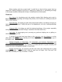
This project works on the prototype of support pole originally developed by the student
Teemu Kuusisto in his Master's Thesis. The prototype consists in a pole with a handle that
moves along a rail located on the ceiling of the test bed. This support can extend and
contract itself, tightening and loosening between the floor and the ceiling. When the pole is
fully tightened, it can be used as a support that helps people to get up from chairs, beds etc.
A control pad allows the user to control the movement and tightening of the support.
Improvements are made in the original system code. Software errors are fixed and
several functionalities are added, such as collision detection and servo control. Finally, a voice
recognition module is implemented, allowing a user to control the support pole without using
the control pad.
Keywords: Assistive devices, socially assistive robotics, elderly and disabled care, voice
recognition, automation, getting up.
3
4
Before starting with the project itself, I would like to thank all the people that has
helped me, making possible for me to do it, helping me, guiding me, or just making me laugh
in the tough moments. Without all of them, it would have not be the same.
Thanks to:
Panu Harmo, for introducing me to the assistive robotics field, allowing me to work in
this project, as well as guiding me through the process, and of course, for making my stay at
TKK so much warmer.
Anja Hänninen, for helping me with all the bureaucratic affairs, her advice and trying to
help me to stay in Finland. I really felt part of the department, not only a visiting/exchange
student.
Johannes Aalto, for helping me with the technical problems of the project, especially
during the first weeks (and some “sleepy” moments in the last weeks too)…
José Vallet, for encouraging me in pursuing my goals and helping me on getting on
with the Finnish way of life.
To all the friends that have been there, at the next door, at a bus distance or at the
other side of the phone/Skype, warming me in the tougher moments and sharing my joy in
the better ones.
Helsinki University of Technology, the Automation and Systems Department and
Universidad Carlos III de Madrid, for allowing me to live the Erasmus experience: discovering
a country and culture both new to me, finishing my studies abroad in a great university and
meeting so many unforgettable people in the process.
Finland and the Finns, for receiving me with arms wide open and being such a great
country and people… it is a pity that I could not stay here for longer… But I am sure I will
come back someday one way or another… Promise…
5
6
Index
Terms and acronyms
List of figures
8
11
1.- Introduction
13
2.- Description of the existing prototype support pole
2.1.- Prototype overview
2.2.- Hardware description
2.2.1.- Structure of the pole and the test bed
2.2.2.- Motors
2.2.3.- Atmel AT90CAN128 microcontroller
2.2.4.- LIS3L02 accelerometer
2.2.5.- Sliding potentiometer
2.2.6.- Control pad
2.2.7.- Battery and power supply
15
15
16
16
16
17
17
18
18
19
3.- Initial tests with the support pole
3.1.- Manual mode
3.2.- Auto mode
3.3.- Manual and auto mode
21
21
21
22
4.- Ideas for system improvement
4.1.- Improvements to be done in this project
4.2.- Other improvements
23
23
24
5.- Implementation of improvements
5.1.- Optimization and improvements of the original code
5.1.1.- Preparing the original code
5.1.1.1.- Rename files
5.1.1.2.- Delete redundant code
5.1.1.3.- Tightening in auto mode
5.1.2.- Manual control of the tightening
5.1.3.- Tests with the accelerometer: Basic functionality
5.1.4.- Improvements for the accelerometer: Collision detection
5.1.5.- Further improvements with the accelerometer:
"Servo/pushing" control
5.2.- Voice recognition
5.2.1.- Choosing a the voice recognition module
5.2.2.- VRbot overview
5.2.3.- Connecting VRbot to a PC
5.2.4.- Training and testing the module with VRbot GUI
5.2.5.- Testing and supervising the module with HyperTerminal
27
29
29
29
30
30
30
31
32
34
35
35
36
37
38
40
7
5.2.6.- Programming with VRbot to use it in a PC environment
5.2.7.- Connecting VRbot and configure the system to work together
5.2.8.- Implementation on voice recognition instructions in the
program code
5.2.9.- Making it work all together
42
43
44
44
6.- Final tests
6.1- Testing manual & auto mode
6.2- Testing voice recognition
6.3.- Initialization problems
45
45
45
46
7.- Conclusions and future work
47
8.- DVD Attachments
49
9.- References
51
Appendix
A) Loading the code on the microcontroller: Software needed and Bootloader
B) Makefile of the system program
C) VRbot serial protocol
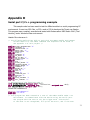
C) Serial port C/C++ programming example
D) Final commented code of the system program
53
57
61
75
81
8
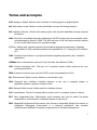
Terms and acronyms
A/D: Analog to Digital. Refers to the conversion of analog signals to digital signals.
AC: Alternating current. Electric current periodically reverses its flowing direction.
AR: Assistive Robotics. Robots that assist people with physical disabilities through physical
interaction.
AVR: The AVR is a Modified Harvard architecture 8-bit RIDC single chip microcontroller which
was developed by Atmel in 1996. The AVR was one of the first microcontroller families
to use on-chip flash memory for program storage.
C/C++: Widely used, general-purpose and procedural language programming language
used widely for both operating systems and applications. C++ being just an evolution
of C.
CAN: Controller Area Network. A peripheral interface targeting automotive and Industrial
applications.
CANbus: Bus communication protocol in the Controller Area Network (CAN).
CPU: Central Processing Unit. The part of a computer system which performs the core
processing functions.
DB9: Common connector type used for RS-232 serial communications in PCs.
DC: Direct current. Electric current flowing in one direction only.
GUI: Graphical User Interface. Interface between a user and a computer system or
application based on graphics instead of text.
GPL: General Public License. Widely used free software license.
I/O: Input/Output. The act of moving data in and/or out of a computer system or device.
I2C: Inter Integrated-Circuit. Multi-master serial computer bus used to attach low-speed
peripherals to a motherboard, embedded system or cell phone.
IDE: Integrated Development Environment, also known as Integrated Design Environment or
Integrated Debugging Environment is a software application that provides
comprehensive facilities to computer programmers for software development.
9
OS: Operative System.
PC: Personal Computer. A computer designed to be used by one individual at a time.
PCB: Printed Circuit Board. Board designed to support and connect electrically the
electronic components of an electronic device.
ROM: Read-Only Memory. Non volatile memory of an electronic device in which the programs
and operating systems are stored.
RS-232: Interface standard for serial data communications in electronic devices.
SAR: Socially Assistive Robotics. Intersection between Assistive Robotics, (AR), and Socially
Interactive Robotics, (SIR).
SIR: Socially Interactive Robotics. Robots whose main task is some form of social or humanrobot interaction.
UART: Universal Asynchronous Receiver/Transmitter. Device in a computer or module that
transforms serial data to parallel, and vice versa.
10
List of figures
(1.1) Population over 65 years old
(2.1) Climb support prototype.
(2.2) Schematic of the prototype's hardware and communications.
(2.3) Zoom of the upper back of the support pole.
(2.4) Zoom of the upper front of the support pole.
(2.5) Control pad: Front view.
(2.6) Control pad: Side view (I).
(2.7) Control pad: Side view (II).
(2.8) Power supply pins: Recharging (Home position).
(2.9) Power supply pins: Not recharging.
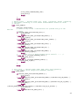
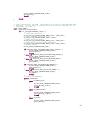
(3.1) Flowchart of the manual mode in the prototype.
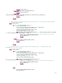
(3.2) Flowchart of the auto mode in the prototype.
(3.3) Flowchart of the initialization routine in the prototype.
(4.1) Alternative structure for the support pole
(4.2) Ability to rotate and servo-arm in the support pole
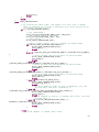
(5.1) Flowchart of the manual mode.
(5.2) Flowchart of the auto mode.
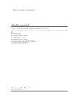
(5.3) VRbot package items.
(5.4) Pin diagram of the VRbot module.
(5.5) External RS-232 board.
(5.6) VRbot - External RS-232 board connection diagram.
(5.7) VRbot - Microcontroller PCB connection diagram
(A.1) Location of the reset and loader buttons in the microcontroller PCB
11
12
1. Introduction
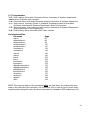
1.1.- Our future1
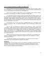
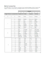
Before any further explanation about the project, it is needed to take a look at the
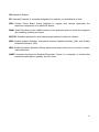
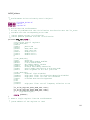
estimates of the future world's population. The following table shows the population over 65
years old by regions (figure (1.1)):
Region
Asia
North Africa/Near East
Sub-Saharan Africa
Europe
North America
Latin America/Caribbean
Oceania
2000
6
4.3
2.9
15.5
12.6
5.5
10.2
Year
2015
7.8
5.3
3.2
18.7
14.9
7.5
12.4
2030
12
8.1
3.7
24.3
20.3
11.6
16.3
(1.1) Population over 65 years old (US Census Bureau, 2000)
As shown in figure (1.1), the group of people over 65 years old in the world will almost
double in only 30 years. The oldest population, 85+ years old, is the most rapidly growing
segment both in Europe and North America. While this is indeed a good sign, direct
consequence of the improving of living standards will also create a social problem that has to
be managed. There is a strong correlation between elders' disability and age, at least 62% of
elders 85+ have difficulty with one or more core activities for daily living. Approximately 10%
of people age 65+ have cognitive impairments that impair functional abilities. The number of
people with disability is estimated around 13% in Europe, and around 15% in the US.
1.2.- Socially Assistive Robotics2
Throughout the world, the elder population, as well as people with disabilities, have
expressed preference to live as independently as possible in their communities. They often
need technological supports to carry out their everyday living objectives. Governments
around the world cannot afford to satisfy all of these needs nor supply those services at this
moment or in the short-term. This is where automation engineering has to take its part,
acting as a social service.
Socially Assistive Robotics (SAR) is a response to these problems. SAR are defined as
1 Information used in the writing of paragraphs 1.1 and 1.2 has been extracted from “The Engineering Handbook of Smart
Technology for Aging, Disability and Independence”; Helal, Mokhtari and Abdulrazak; 2008.
2 Definitions used in 1.2 paragraph have been obtained from “Defining Socially Assistive Robotics”, David Feil-Seifer
and Maja J. Mataric, Interaction Laboratory, University of Southern California. In proceedings of the 2005 IEEE 9th
International Conference on Rehabilitation Robotics June 28 – July 1, 2005, Chicago, IL, USA.
13
the intersection of Assistive Robotics (AR), robots that assist people with physical disabilities
through physical interaction, and Socially Interactive Robotics (SIR), robots whose main task
is some form of social or human-robot interaction. SAR share with AR the goal to provide
assistance to human users, but, as SIR, this assistance is through social interaction. In SAR,
the robot's goal is to develop close and effective interaction with the human user for the
purpose of giving assistance and achieve measurable progress in convalescence,
rehabilitation, learning, etc.
The defining characteristics of the SAR are the following:
- Reliability, Security and Safety: The most important factors, when a robot is used by a
person, errors are not allowed because it could result in injuries.
- User interface: Non complex, accessible and personalized user interfaces are required.
- Mechanical and Ergonomic Infrastructure: It has to be easy to install in another place.
- Hardware and Software: Real time operating systems, algorithms and software architectures
should be enhanced to perform a suitable control of the mechanical structure.
- On top of all of these characteristics, users' acceptance of SAR robots and devices is the
most important factor of all. They have to be easy to use, non intrusive and feel as part of
the environment.
This project is under the field of SAR. There are a lot of possible developments in this
field and technological advances and researches will lead the way for more.
1.3.- Getting up assistive technology and automation
One of the problems usually elderly people have is the difficulty of getting up when
they are sat or laid down. This project is the first one centered in solving this problem:
assisting elderly people in getting up from chairs, beds etc.
The project was already started, as part of the Master's Thesis work of Teemu
Kuusisto, student of the Automation and Systems Department at Helsinki University of
Technology. At the beginning of this project, a prototype was already designed and
constructed, but the managing and controlling software was unfinished.
The main purpose in this project is to improve the original prototype fixing any
possible error in the original software and adding some basic functionalities. After the work of
this project has been done, the prototype should be a step closer from being a standalone
product that, with further developments especially in the design phase, could be actually used
in a real environment.
14
2. Description of the existing prototype support
pole
In this Final Project improvements to an unfinished prototype of climb support are
made. The prototype was created by Teemu Kuusisto in his Master's Thesis project. Prior to
starting working with the improvements, it was necessary to study how this prototype is
constructed and how it works.
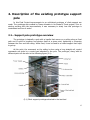
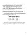
2.1.- Support pole prototype overview
The prototype is basically a pole with a handle that moves on a ceiling along a fixed
path and it's able to lengthen and shorten itself at a given point, tightening or loosening
between the floor and the ceiling. While fixed, it can be used as a robust support that helps
to get up.
At this point, the movement on the ceiling is done using a long straight rail, control
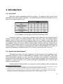
commands are given by a control pad attached to the pole. The prototype, along with its
different parts can be seen in the following figure (2.1):
(2.1) Climb support prototype attached to the test bed
15
2.2.- Hardware description
In this section an overview of all the main components used for the construction of the
prototype will be made, in order to understand better its functioning.
2.2.1.- Structure of the pole and the test bed
As shown in the figure (2.1), the structure is archway-shaped and it is designed to
support the weight of the prototype, as well as to make it stable. It has a rail on the top
crossing the structure lengthwise in which the support is located. Along this rail there are
three virtual locations, being the left end position “home”, right end position “chair”, and the
middle of the rail position “bed”.
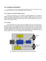
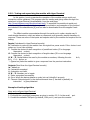
2.2.2.- Motors
All the movements of the support pole are provided by the action of two DC motors.
One of the motors moves the support along the ceiling rail, while the other shortens and
lengthens the pole to fix it (tighten it) between the ceiling and the floor. The motor moving
the support leftwards/rightwards along the rail is monitored and controlled by TechnoSoft's
PIM3605 Intelligent Control Module using CANbus communication. The tightening motor is
directly controlled by the microcontroller using its digital outputs. More information about the
motor controller can be found in its datasheet [1] and user's guide [2].
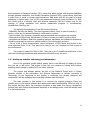
(2.2) Schematic of the prototype's hardware and communications
16
2.2.3.- Atmel AT90CAN128 microcontroller
The AT90CAN128 is an 8-bit general purpose microcontroller with several add-ons to
improve its communication and storage capabilities. Extensive information of the
microcontroller can be found in its datasheet [3].
All of the prototype's control and calculations, save those related with the movement
motor, are performed in it. The software implemented is mainly an interrupt driven state
machine that checks the inputs, outputs and states of the climb support. It gives the proper
commands to the tightening motor and the motor controller and makes the calculations and
A/D conversions required for it. It also communicates with all the other hardware elements of
the system in many different ways and protocols (See figure (2.2)):
− CANbus for communicating with the motor controller.
− Serial communication through one of its two UARTS for PC connection (to load the
code on the ROM and for supervising tasks)
− I2C bus for communication with the accelerometer.
− Digital I/O used with the control pad and sliding potentiometer.
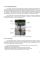
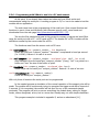
2.2.4.- LIS3L02 accelerometer
LIS3L02 is a 3-axis accelerometer used to measure the leaning of the support. The
three axis values given are 12-bit integers (thus, being between 0 and 4095). The
communication standard between the accelerometer and the microcontroller is I2C protocol.
More information can be found in its datasheet [3].
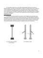
(2.3) Zoom of the upper back of the support pole
17
2.2.5.- Sliding potentiometer
The support can extend and contract itself, being able of getting fixed between the
floor and the ceiling along its path. When the support extends itself to get tight, it has to be
sure it reaches a tight value enough to safely support the people leaning on it. This is where
the sliding potentiometer takes its part, by continuously measuring its resistance (linear with
the position of the support). When this value surpasses a certain limit (established
experimentally by testing), the motor will stop and the support will be tightened enough.
As the values given by the sliding potentiometer are analog, it is needed a conditioning
and amplifying circuit, as well as an A/D converter to be able to read them with the
microcontroller through one of its I/O digital ports.
(2.4) Zoom of the upper front of the support pole
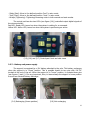
2.2.6.- Control pad
The control pad is used to give the proper binary commands to the support to make it
work. The commands given are read by the microcontroller, which then gives the proper
commands to the motor controller. Each button of the control pad is connected to a pin in
one of the I/O digital ports of the microcontroller.
-
These are the buttons used in the control pad (see figures (2.5), (2.6) and (2.7)):
On/Off switch: Turn on/off the device.
Auto/Man switch: Mode selector between manual and auto modes.
Vasen/Oikea (Left/Right) button: Move left/right orders in manual mode.
Koti (Home): Move to the defined position “home” in auto mode.
18
- Sänky (Bed): Move to the defined position “bed” in auto mode.
- Tuoli (Chair): Move to the defined position “chair” in auto mode.
- Kiristys (Tightening): Tightening/Loosening order in both manual and auto modes.
The control pad has also two LEDs (see figure (2.6)) controlled output digital signals of
the microcontroller:
Red LED: Ready LED, turned on when the system is waiting for a command.
Yellow LED: Action LED, turned on when the system is performing an action.
(2.5),(2.6) and (2.7) Control pad: front and side views
2.2.7.- Battery and power supply
The support is energized by a 12V battery attached to the pole. This battery recharges
when the support is in “home” position. This is possible thanks to two pins with 12V DC
located at the end of the rail. When the support is in “home” position, it contacts those pins
(see figures () and ()). It's very important, then, to leave always the support in home position
to avoid an eventual battery discharge.
(2.8) Recharging (Home position)
(2.9) Not recharging
19
20
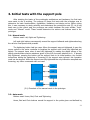
3. Initial tests with the support pole
After studying the basics of the prototype's architecture and hardware, the first tests
were made to see it working. The purpose of these first tests with the prototype was to
determine its basic functionalities, capabilities, limitations and design errors. Before doing
this, it was necessary to study carefully and understand the prototype's code [5]. As it has
been seen in the control pad, the prototype can switch between two main modes: "Auto"
mode and "Manual" mode. These modes determine the actions and buttons used in the
prototype.
3.1.- Manual mode
Buttons used: Left, Right and Tightening.
Left and right buttons consequently moved the support leftwards and rightwards along
the rail at a fixed speed while pressed.
The tightening button had two uses: When the support was not tightened, it gave the
proper orders to the motor controller to lengthen the support until it was fully tightened and
steady. The support knew when it was fully tightened by reading the digital values of the
sliding potentiometer electric resistance given by the A/D converter attached to it. If already
fully tightened, pressing the button got the support back to its initial position. Any further
instructions during the tightening or loosening of the support were ignored: this operation
could not be stopped. When the support was fully tightened the only instruction accepted was
loosening, any other commands were not read.
(3.1) Flowchart of the manual mode in the prototype
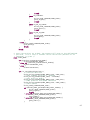
3.2.- Auto mode
Buttons used: Home, Bed, Chair and Tightening.
Home, Bed and Chair buttons moved the support to the points given and defined by
21
the Home, Bed and Chair states. This movement could only be stopped if a switch to manual
mode was made, but not in auto mode. Thus, while getting to the desired position, no more
actions could be done. These positions were defined in the program to be in the left (Home),
middle (Bed) and right (Chair) of the rail.
The Tightening button was supposed to work in the same manner as in the manual
mode, but it did not. This created the additional problem of not being able to control the
system in auto mode if the support was previously tightened in the manual mode.
(3.2) Flowchart of the auto mode in the prototype
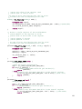
3.3.- Auto and Manual modes:
Both modes worked together with the accelerometer: When moving, tightening or
trying to, the accelerometer values were read, and if they were above the predefined limits
the instructions were discarded and the movements were not done. The purpose was that the
support moves/tightens only when its position is vertical, that is, not leaned in any direction.
However, this function, though implemented in the code, did not work properly. The support
could be leaned in any direction but it still moved and tightened, even if forcefully shook.
Another flaw present in the prototype was that its movement was not symmetrical:
The speed in which it tightened/loosened and moved left/right was not the same, and
sometimes when the support loosened, it did not reach the original position it had before,
being longer, then. It seemed to be more a flaw of the motor/motor controller than of the
programming and control of the prototype, though.
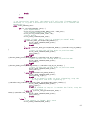
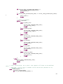
It is also needed to mention the implemented initialization routine. When turning on
the device, no orders were accepted until the support was loosened and in the “home”
position. This routine was tested many times and it worked correctly.
22
(3.3) Flowchart of the initialization routine in the prototype
4. Ideas for system improvement
The prototype structure is fully functional, but there is a lot of room for further
improvements, which in fact have to be added if it has to meet its targets' requirements. That
is, there is still a lot of work needed before it can be of any actual use for elderly and disabled
people. Many of these improvements, however, are not under the range of this project. The
improvements and work in this project are done with the hardware already in use, with the
chance of adding new modules to the original prototype model, but not modifying its basic
structure.
Below there is a detailed list of ideas for system improvement, separated in two
groups, those improvements that will be made in this project and those which will not.
•
•
•
•
•
•
•
•
•
•
•
Code changes and improvements
Make the accelerometer work properly
Basic collision detection
Manual control of the tightening
Voice recognition
Basic servo control
Improved movement on the ceiling
Distributed computing
Ability to rotate
Improved servo control
Robotic/Servo arm
4.1.- Improvements to be done in this project
Code changes and improvements
Writing such a long code without any flaw it's quite a difficult task. Usually there is
always plenty of room for improvements and debugging usually detected by those who didn't
write the code the first time. Thus, at the same time I work in the other improvements, some
code changes will be made, and some structures and algorithms will be simplified, trying to
maintain the compatibility with the rest of the system.
Make the accelerometer work properly
This is the main error of the prototype, the accelerometer doesn't seem to work during
the initial tests. This problem has to be solved in this project, so the support does not try to
tighten or move when it is leaned in any direction, as it can be dangerous for the support
23
itself.
Basic collision detection
As it is now, the support moves when an instruction is given, but it will continue to
move even if an obstacle is in its way. This, of course, can be dangerous, so at least some
kind of collision/obstacle detection has to be implemented. If the support encounters any
obstacle preventing the movement along its path, it has to stop until the obstacle is removed.
Manual control of the tightening
Not strictly necessary for the final product, but very useful during developing and
testing is the addition of a manual control of the tightening, that is, being able to move the
support up and down as the user wants. It will also help to solve partially the asymmetrical
movement mentioned before when tightening/loosening the support.
Voice recognition
The control pad is useful for testing purposes and quite fast for system development,
but it's not the ideal controlling scheme for the target users. Many elderly and/or disabled
people won't find themselves comfortable having to control the support with a control pad.
Easier to use control methods should be implemented, widening also the range of possible
users. One of these control schemes is voice recognition. In my opinion adding a voice
recognition module to the support will make it more user-friendly, since it does not require
that users actually see or know where the pad is. The support could be then controlled using
speech recognition only.
Basic servo control
Getting rid of the control pad and make the system easier and more forward to use is
one of the main objectives of this project. Along with voice recognition, there is another
control method that is, in addition, quite simple to implement in its basic form: Servo control.
If the user wants to go forward with the support, it can be done by simply leaning the
support in the desired direction. The accelerometer will detect this, the motor will be
activated and then it will move the support in the desired direction.
24
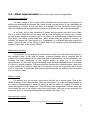
4.2.- Other improvements (out of this project work and capabilities)
Movement on the ceiling
The basic design of the on-rails ceiling movement for the prototype is functional for
testing and development purposes, but needs a total overhaul before it can realistically be
implemented in a house. It now only works in a straight line, but the ability to turn and/or
have crossroads should be implemented to export the system to a real house environment.
In any case, the on-rails movement is limited, as the support pole can't move freely,
that is, it has to follow the rail, not being able to cover the space of a whole room. A more
evolved system should be the way to go in the future. For example using wheels both in the
floor and in the ceiling at the same time, which would allow the support to move in an
effective 360 degree arc (See figure(4.1)). Investigation of a different approach around this
matter (robots moving on the ceiling) is being done at the moment by the Automation and
Systems Department in the project Ceilbot3.
Distributed computing
The prototype is now working as a stand-alone model, but it will really have sense in a
fully domotic house. In this kind of houses, a central computer with a powerful and all
purpose CPU would manage all the electronics and communications. All the calculations not
involving the basic movement of the support should be done out of its internal
microcontroller. So, the voice recognition module would be better implemented and processed
if it was in a central computer. The same could be said about its location system, which now
is really simple, but should be improved if the support has to move along the entire house
more or less freely. It would also allow some improvements like the ability to call the support
if it is in another room.
Ability to rotate
The support pole, as it is now, moves along the rail, but it cannot rotate. That is, the
handle is always in the same direction. While not compulsory if a proper movement system in
the ceiling is implemented, it would be useful to add the ability of rotating, the ability to
rotate the support in a 360 degree arc. This will really make things easier for their users, and
would make the use of the support pole more comfortable. With the current structure this
cannot be done, so an improved architecture is needed. See figure (4.2)
Improved servo control
3 More information about the Ceilbot project can be found on http://autsys.tkk.fi/en/Ceilbot
25
In this project a basic servo control will be implemented, but this servo control is
flawed by design. It is using an accelerometer to detect if it is being pushed or not. While this
works, it implies that the support pole has to be leaned in the direction the user wants it to
move. Furthermore, the accelerometer used works also with the collision detection feature,
and it is quite tricky for the system to determine if the cause of its leaning is due to a collision
or of a user pushing the pole. It would be more elegant and precise the addition of hardware
modules to do this task.
Robotic/Servo arm
If all the previous improvements were made, a good addition that would really help
disabled and elderly people would be a robotic or servo arm. The climb support is created to
help people to get up and move through the house, but it doesn't help that much if they have
to crouch (“get down”) to get something from the floor. In addition, doing it is usually a hard
task for elderly people. Attaching a robotic arm (whether servo controlled or not is a design
and economic decision) would help people in everyday house works and situations.
(4.1) Alternative movement
on the ceiling
(4.2) Ability to rotate
26
5. Implementation of improvements
In this section all the improvements and additional features listed in section 4.1 will be
implemented. Later on, these improvements will be tested and evaluated.
Along this section, reference to files, code and states and/or function arguments will
be made. To quickly identify them they will be written as:
- Files in italics. i.e. state_machine.c
- Code in a different font. i.e. is_straight (int state)
- States/Arguments in capital letters. i.e. STATE_MOVE_RIGHT
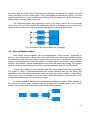
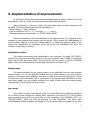
Before the depiction of the implementation of the improvements, flow diagrams of the
operation of the intended final support pole are shown. They increase the understanding of
the full system, and put in context the added features. In these flow diagrams, states in the
system are represented by rectangles, while the arrows are commands that allow the
transition of one state to another.
Initialization routine
This routine was already well implemented in the prototype. The state “NOT READY”
loosens the support pole and then moves it to the home position. State “NONE” is a temporal
state used to read the mode switch, and the system will end always in AUTO or MANUAL
states, which then will be waiting for the proper commands. See figure (3.3)
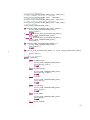
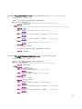
Manual mode
The states reachable by the manual mode can be identified from the state diagram
shown in figure (5.1). As the majority of states only work while a button of the control pad is
pressed (or the support pole pushed), they have to return to the manual wait state to be able
to accept any other commands. This is represented in the diagram with bidirectional arrows.
New states added over the original prototype are green colored, while the states already
implemented in the prototype are blue colored.
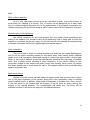
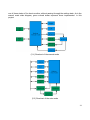
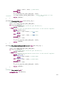
Auto mode
Auto mode is similar to the manual mode. The main difference is that state transitions
do not have to pass through the “waiting state” necessarily (See figure (5.2)). All the states
can be activated using both the control pad or voice recognition, save “MOVING_LEFT” and
“MOVING_RIGHT”, which can only be activated by voice recognition. The linear “bus”
communication scheme between the states on the left shows that the system can go from
27
one of these states of the bus to another without passing through the waiting state. As in the
manual mode state diagram, green colored states represent those implemented in this
project.
(5.1) Flowchart of the manual mode
(5.2) Flowchart of the auto mode
28
5.1.- Optimization and improvements of the original code
Prior to start adding any new hardware to the prototype, many improvements in the
original code are made. These changes are described in this section and are also listed in
chronological order: The later an improvement is listed, the later was implemented in the
prototype.
NOTE: The program managing everything in the support is mainly an interrupt driven
state machine (being programmed the state machine in files statemachine.c and
statemachine.h and the interrupts in files interrupts.c and interrupts.h). This state machine
function has defined states for each and every of the actions the support can make. That is
why many times in this section references to this state machine and its states are made.
5.1.1.- Preparing the original code
After studying the code, it was decided to start with 3 simple tasks. First, renaming
Finnish names to English names; second, deleting of redundant code; and third, fixing the
not working tightening feature of the auto mode.
5.1.1.1.- Rename files
Many of the files had already English names, as they consist of GPL source code files
directly used to control and configure the system's hardware. There are many others though,
developed by Teemu Kuusisto, the prototype's designer, that had Finnish names. List of the
renamed files:
tanko.c
main.c
napit.c
statemachine.c
napit.h
statemachine.h
moottori.c
motor.c
moottori.h
motor.h
ledit.c
leds.c
ledit.h
leds.h
keskeytys.c
interrupts.c
keskeytys.h
interrupts.h
liukupotentiometri.c
slidepotentiometer.c
liukupotentiometri.h
slidepotentiometer.h
summeri.c
buzzer.c
summeri.h
buzzer.h
Makefile is also changed accordingly.
29
5.1.1.2.- Delete redundant code
The original code was using two different files, as well as their two attached respective
header files, for the accelerometer control. As this is not necessary, these files were merged
into one file. Files accelerometer.c and kiihtyvyysanturi.c
are merged into one,
accelerometer.c (same for header files).
This leads to redundant code, functions with different names but same purpose, so these
functions are deleted and calls to these functions fixed.
5.1.1.3.- Tightening in auto mode
This feature was missing in the original prototype. The states managing the
tightening/loosening of the support (STATE_TIGHTENING, STATE_TIGHTENED and
STATE_LOOSENING) were prepared to work both in manual and auto modes, but not the
states managing the auto mode (STATE_AUTO, STATE_HOME, STATE_BED and
STATE_CHAIR). The solution was, then, to add the code to these states in a similar way it
was implemented on the manual states.
5.1.2.- Manual control of the tightening
The addition of the manual control of the tightening required more work.
The purpose was to give the ability to the support of moving up and down when with the
appropriate commands with the control pad, thus, tightening and loosening manually. The
control pad had no “free” buttons to use, so buttons “Home” and “Bed” will be used as if they
were “manual tightening” and “manual loosening” buttons in the pad. These buttons are not
used in the manual mode, only in the auto mode, so they won't create any
incompatibility/error in the system. The relative position of the buttons in the pad helps to
remember their function.
The system's state machine had defined states for tightening and loosening, but these
states ignore any order while working. More states have to be defined and programmed to
implement the manual control of the tightening, then. Two states will be created:
STATE_MANUAL_TIGHTENING and STATE_MANUAL_LOOSENING.
In STATE_MANUAL_TIGHTENING the support moves down (tightening) while the
button “manual tightening” is pressed. STATE_MANUAL_LOOSENING does the opposite,
moving the support up (loosening, then) while the button “manual loosening” is pressed.
These states are quite similar to the manual states “STATE_LEFT” and “STATE_RIGHT”, which
move the support leftwards and rightwards while the proper button is pressed.
It is needed also to read the values of the sliding potentiometer when manually
30
tightening, as it is implemented in the state in which the support tightens automatically
(“STATE_TIGHTENING”), to prevent malfunctions and accidents. There is no need for adding
a limit when going up, as if the upper limit is reached, the motor just stops.
It is important to notice, though, that at this point of the project the manual control of
the tightening was implemented only for test purposes and also to start working and getting
familiar with the system's code. It worked, but the accelerometer still did not. It was possible,
then, to tighten the support even if it was not straight. This problem was solved in the next
section.
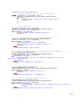
5.1.3.- Tests with the accelerometer: Basic functionality
In the testing phase it was clear that the accelerometer was not working well. The pole
could be moved violently in any direction but that did not affect any of the actions of it. After
examining the code and doing some tests printing the values of the accelerometer x, y and z
axis, the cause of the error came out, it was not working due to the loose values given in the
function supervising them.
This function, is_straight(), implemented in the original code, determines if the support
is straight enough to be able to move or tighten. If the values given by the accelerometer
exceed the predefined limits of is_straight(), any movement instruction will be ignored.
Thus, printing the values of the 3 accelerometer axis and checking the state of
is_straight() function, along with iterative testing allowed to fix the problem. After this
improvement, if the support is leaned a bit, about 3 degrees, it stops moving. The values are
at this point quite tight, but this was done on purpose, as it is designed to work together with
further improvements on the accelerometer control that will be done in the following sections.
NOTE: It is important to notice that these values obviously depend on the position and
orientation of the accelerometer along the support. If the accelerometer is moved somewhere
else, the values have to be configured again.
31
5.1.4.- Improvements for the accelerometer: Collision detection
The accelerometer routine previously implemented is just a basic functionality but it is
only truly designed for a static support, that is, when it receives instructions being static or it
is tightening/loosening. When the support is moving the values of the accelerometer are not
exactly the same, and the tight, static, predefined values do not fit, continuously stopping the
movement. It is needed, then, to improve is_straight() function, so it can identify
whether the support is moving leftwards or rightwards. In addition, while doing this, it can
also be implemented collision detection.
The objective, then, is that the support moves knowing the direction in which is
moving, and if it encounters something in its way that prevents it to move, it has to stop,
avoiding any damage/trouble. This can be done because when the support collides with an
object, it will still try to move, leaning in the direction of its movement. The accelerometer will
detect this leaning and is_straight() function should prevent the support of moving
further. The following code changes will try to implement this collision detection in both
manual and auto modes.
The values for the accelerometer when the pole is moving will be asymmetrical,
depending on the support moving leftwards or rightwards. Some extra definitions are
required, as well as changes in the code of the function is_straight(). These changes
are different in manual and auto modes.
The first step for doing this is reading the accelerometer values when the support
moves to the left and right both in manual and auto modes. These values are different when
moving left or right but the same when moving in auto or manual modes. With these values,
the new limits that will be used by is_straight() when the support is moving in any of
the two directions can be defined. Then, the function has to know whether the support is
moving to the left, to the right or if it's static and define the proper limits.
We need that is_straight() function reads the movement of the system. For doing
this the function will read the movement as an argument given by the state machine. Will be,
then:
is_straight (int state)
Being the defined “state” values
1: If moving left ( state = MOVING_LEFT)
2: If moving right ( state = MOVING_RIGHT)
0: Rest of cases ( state = STATIC)
This is easy to do in manual mode, as all the states will call function
is_straight(STATIC), save the states “STATE_LEFT”, and “STATE_RIGHT” which will call
the function is_straight(MOVING_LEFT) and is_straight(MOVING_RIGHT).
32
Auto mode is, however, a bit tricky. As “Home”, “Bed” and “Chair” positions are
defined, it is known that when pressing “Home” button the support will go to the left no
matter what is position was (so it has to call function is_straight(MOVING_LEFT)). It is
also known that when pressing “Chair” button the support will go to the right (calling function
is_straight(MOVING_RIGHT), then) but the movement when the support goes to the
position “Bed” is not clear. So, for “bed” position it is needed to implement an algorithm to
identify the direction of the movement.
For calling the correct is_straight(movement) function, the state of the system is
saved in an additional variable. This state, however, is not the same as that of the state
machine, but a special one which saves the value of some of the previous states. For
example, when going from home to bed, this variable will save the value “STATE_HOME”, and
when going from chair to home, the value will be “STATE_CHAIR” instead. So, comparing the
actual state “STATE_BED” with the previous state, we now the direction of the movement.
This state is not saved when the support is tightening, so the value will be always or
“STATE_CHAIR” or “STATE_HOME”, but it will be reset if we go to the manual mode.
These code changes effectively improve the accelerometer routines and implements
collision detection. It has to be said, though, that due to the extreme sensitivity of the
accelerometer, the values change constantly even if the support is still. This is why the limits
established for the collision detection can't be too tight. So, this code “detects” objects when
the support is leaned more than 2 – 3 degrees, and in that case, stops its movement.
33
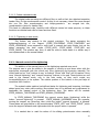
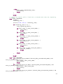
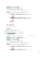
5.1.5.- Further improvements with the accelerometer: "Servo/pushing" control
The objective now is to implement some basic “servo” control of the support. That is, if
a user wants to move the support pole in a direction, he/she will not have to necessarily use
the control pad, just pushing the pole in the desired direction should work also. As it is
understandable, this will only be implemented in manual mode.
As the prototype has no “push detector”, this functionality will be based on the
previous modification for obstacle detection code. If the support is in manual mode and
stopped, it will read the values of the accelerometer. If these values show a significant
change in the “y” axis of the accelerometer, which is parallel to the axis of the pole, it will
give the proper commands to the motor to move in the direction being pushed. It's quite
similar to the previous modification, but with a change in the accelerometer threshold.
Two new states are created in the state machine, “STATE_PUSH_LEFT” and
“STATE_PUSH_RIGHT”. They will only be reachable when in manual mode and the common
static values of the accelerometer are surpassed. As stated before, if these values show a
significant change in the “y” axis, the state machine will go to one of these two new states.
These
states,
then,
will
call
is_straight(PUSHING_LEFT)
or
is_straight(PUSHING_RIGHT), which will have special accelerometer limits. If the values
of the accelerometer are within these limits, the support will continue moving in that
direction. These values have been obtained by iterative testing, in order to make the support
to move only when pushed.
This new feature improves also the operation of the collision detection tasks. This is
because if an obstacle is met, the support pole stops, and then, it will deter that it is being
pushed by this obstacle. It will then move in the opposite direction of the obstacle, not totally
separating from it, but lessening the strain on the obstacle.
34
5.2.- Voice recognition
Voice recognition implementation is the most complex and large part of all the
improvements made on the original prototype. In this project, voice recognition will be
implemented on the prototype.
5.2.1.- Choosing a the voice recognition module
After studying the matter, it was clear that the microcontroller AT90CAN128 was not
capable of doing the task. Voice recognition is quite demanding in terms of processing power
and the chip is already overwhelmed when doing other tasks (i.e. in A/D conversion with the
sliding potentiometer). Thus, an additional module should be added. Before choosing any
systems, the requirements needed for our system, as well as the limitations imposed by it
have to be studied.
It has to be able to replace the control pad. The system needs to recognize only a few
simple commands, not many more than buttons in the pad. A full, expensive, high-end voice
recognition system is not needed, then. Something simple and cheap should work.
After the requirements for the operations have been defined, the limitations of the
system have to be considered. These limitations are, mainly, the available connection
protocols between the module and the microcontroller PCB. Apart from its I/O digital ports,
the AT90CAN128 microcontroller has 2 serial ports, one of them is used while programming
and debugging, but the other is free and accessible. Thus, the connection can be made using
digital inputs via the I/O ports of the microcontroller or using the serial port available.
After doing some research around the Internet and getting more detailed information
about various competitive products (asking store managers), it was chosen the “VRbot”
recognition module, from VeeaR (http://www.vee-ar.com/).
35
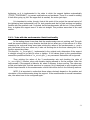
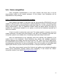
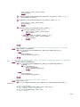
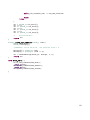
5.2.2.- VRbot overview
VRbot is a small, simple and inexpensive voice recognition module designed to work in
robots, specially with Robonova series. It can communicate with other devices using a UART.
Key features:
• 26 built-in speaker independent (SI) commands for ready to run basic controls
(currently supports US English, German, Italian and Japanese).
• Supports up to 32 user-defined Speaker Dependent (SD) triggers or commands as well
as Voice Passwords. SD commands are language independent.
• Easy-to-use and free simple Graphical User Interface to program Voice Commands.
• The module can be used with any host with an UART interface (powered at 3.3V - 5V).
• Serial protocol to access and program the module through the host board, operating
from 9600bps to 115000bps.
Hardware included in the package:
•VRbot PCB
•Microphone
•Cables for the serial connection
(5.3) VRbot package items
36
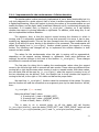
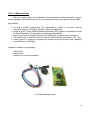
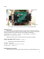
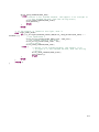
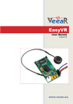
5.2.3.- Connecting VRbot to a PC
To start the testing of VRbot module, it has to be connected to a PC first. As it is
specifically designed for being used with Robonova robot series and they are not used in this
project, a generic external RS-232 board with a DB9 connector has to be used to connect the
module to a PC. A 5 Volt DC power supply will be needed for both modules. Detailed
information can be found in its datasheet [7].
(5.4) Pin diagram of the VRbot module.
(5.5) External RS-232 board.
(5.6) Connection diagram
Serial port communication parameters of the module:
• Baud Rate: 9600 (default), 19200, 38700, 57600, 115200
• 8 Data bits
• No parity
• 1 Stop bit
• No flow control.
As the microcontroller AT90CAN128 by default has the same parameters for the serial
communication, nothing has to be reconfigured or changed to interconnect them. These
parameters are needed when programming and testing the system with a PC, though.
37
5.2.4.- Training and testing the module with VRbot GUI
With the module connected, its graphical user interface (GUI) has to be opened, VRbot
GUI (downloadable from the web page of the supplier) and press 'connect'. A detailed tutorial
of how to teach and train commands is also downloadable [8].
There are two types of words that can be recognized by the module. Speaker
Independent commands (SI), and Speaker Dependent commands (SD).
SI commands are built-in recognition patterns included within the device's firmware. As
the time goes by, the supplier will update these patterns to add more SI commands in more
languages. As this project is being written, there are 25 SI commands in each of these 4
languages: English, German, Japanese and Italian. However, in this project, these commands
are not being used, as they are prepared for working with the Robonova series robots, but
they are not enough for this system.
SD commands, are, on the other hand, commands that have to be taught to the
module, and they are, then, not language dependent. The SD commands are used in this
project.
Both SI and SD commands are divided in two categories, “trigger words” and
“commands”. Trigger words are used to prepare the module for receiving a command. They
are not needed, but they are useful to avoid recognition of words when the user does not
want to. The common use of trigger words is to have the module waiting for recognize a
trigger word, and then, if it is recognized, start the recognition of the commands. Trigger
words have also different recognition rules, the module is not as restrictive with these words
as it is with commands.
When managing the instructions and commands with VRbot GUI, the instructions are
divided in “wordsets”. Wordset 0 is reserved for trigger words, while wordsets 1 to 15 are
reserved for commands.
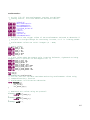
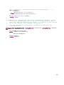
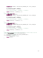
The following instructions have been taught to the module (note that the word in
capital letters is the word that has been taught to the module):
Wordset 0:
-INSTRUCTION: This is the trigger word. If a user wants the module to recognize any of the
commands below, first he will have to say this word: “Instruction” and then any of the
commands. It is important to notice that due to the limitations of the module, a pause of
about 2 seconds is needed between commands.
38
Wordset 1:
-Command 0: LEFT: When this order is given, the support should move leftwards only
stopping when the system receives another order or reaches the end of the track.
-Command 1: RIGHT: As LEFT, but going rightwards.
-Command 2: GO_HOME: Same function as button “Home” in the control pad.
-Command 3: GO_TO_BED: Same function as button “Bed” in the control pad.
-Command 4: GO_TO_CHAIR: Same function as button “Chair” in the control pad.
-Command 5: TIGHTEN: Same function as button “Tighten” in the control pad.
-Command 6: STOP: Order needed to stop the device when moving, as actions will be carried
out until finished if no other command is recognized.
After teaching these instructions, they can be checked with the program to verify a
correct recognition of the command words. It is time, then, to supervise the module
operation.
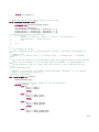
The commands used for working with the device are English commands, but wordsets
2 and 3 have been used for Spanish and Finnish commands. These wordsets have also been
tested. The commands taught to the module are, then:
#
0
1
2
3
4
5
6
Words et 1
Left
Right
Go hom e
Go to bed
Go to c ha ir
Tighten
Stop
Words et 2
Va sem m a lle
O ikea lle
K otiin
Sä nkyyn
Puolille
K iristys
Seis
Words et 3
Izquierda
De rec ha
A c a sa
A la c a m a
A la silla
Tensa r
Pa ra
Along this project only wordset 1 has been used for development. However, it is really
simple to use wordsets 2 and 3 as well. A language selector could be added to the system
also.
39
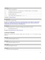
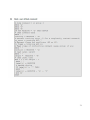
5.2.5.- Testing and supervising the module with HyperTerminal
In this section, how to supervise the operation of the module using a serial port
connection will be explained. The program used for reading and giving orders through the
serial port is HyperTerminal (downloadable from the web page:
http://www.hilgraeve.com/htpe/download.html). To supervise the module via serial port,
understanding how it really works is required. Documentation and examples of the protocol
are included in the attachments [9] and can also be downloaded from the supplier's web
page.
The VRbot module communicates through the serial port in quite a simple way. It
reads simple characters, which are taken as commands, and gives also simple characters in
response. These are some of the inputs and outputs used by the module and required for the
testing.
Inputs (Introduced in HyperTerminal console)
'b': Instruction to wake up the module from its original low power mode. If the device is not
waken up, it won't do anything.
'i': Prepare the device to start recognition of predefined orders (SI or language
dependent orders).
'd': Prepare the device to start recognition of taught orders (SD or non language
dependent orders).
'A','B'...'Z': Capital letters are used by the module as numbers, following the rule
A=0;
B=1; C=2... and so on.
' ': (Space bar) Asks the module to give a response from the previous instruction.
Outputs (Read from the HyperTerminal console)
'w': Waken up.
'o': Instruction accepted.
'v': Instruction not valid.
'A','B'...'Z': Numbers, as in inputs.
'r': Order recognized successfully.
'e': Error. When the device detects an order but can't identify it properly.
't': Timeout. Output signal if in the defined timeout time (5 seconds by default) no
instruction is given/detected.
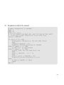
Example of testing algorithm
Open and configure HyperTerminal
1- Open HyperTerminal program
2- Configure the connection parameters as given in section 5.2.3. for the serial port
3- Connect the suitable COM port (by default, COM port 1) and open the console.
40
Waking up the device
4- Wake up the program. To do this, introduce letter 'b' until the module answers 'o',
indicating it is ready.
5- If the module was not used with VRbot GUI previously, it should answer first 'w', so it has
waken up, and then 'o'. If the module was already waken up (i.e. it was already used with
VRbot GUI) the answer will be 'o', so its already waken up.
Test a Speaker Dependent command (Example: Command GO_HOME)
6- Press 'd'. There will not be any answer. The device prepares for SD commands recognition.
7- Press 'B', the number of the wordset in which the command for recognizing is located. (As
already explained, numbers are 'A'=0, B='1', C='2'... Command GO_HOME is in wordset 1, so
'B')
8- Say the command before the default timeout expires (5 seconds).
9- Wait for the system's response.
10- There are three possible responses:
't', timeout, no word was spoken before the timeout.
'e', error, error during recognition or confusing results.
'r', command recognized, the words said fit within the patterns of one of the
commands in wordset 1.
11- If answer was 't' or 'e', start again from step 6. If answer was 'r', press space bar.
12- The device will answer the number of the command recognized from the specified
wordset. If it recognized properly GO_HOME command, answer should be 'C', command 2
from the wordset.
Built-in instructions can also be tested by pressing 'i' instead of 'd' in step 6. The
language for these instructions by default is English.
The whole module can be configured, taught and tested by this procedure.
41
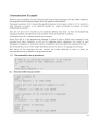
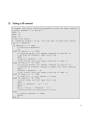
5.2.6.- Programming with VRbot to use it in a PC environment
At this point, it has already been tested and observed how VRbot works and
communicates using the serial port. A working program in C/C++ has to be made to test the
module with an application.
The main issue here is the programming of the serial port. Open source libraries and
functions to use in Linux and Windows (with the same source code), were found and
downloaded from the web page http://www.teuniz.net/RS-232/ [10].
Two are the files needed and used in this project to connect, program and test VRbot
using the serial port with a PC: rs232.c and rs232.h. The header file rs232.h contains all the
definitions needed by the source code file rs232.c
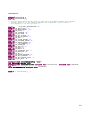
The functions used from the source code rs232.c are:
int OpenComport(int comport_number, int baudrate)
Opens the COM port “comport_number”. “baudrate” is expressed in baud per second
(i.e. 115200). Returns 1 in case of an error.
int PollComport(int comport_number, unsigned char *buf, int size)
Gets characters from the serial port “comport_number” (if any). “buf” is a pointer to a
buffer and “size” the size of the buffer in bytes.
int SendByte(int comport_number, unsigned char byte)
Sends a byte via the serial port “comport_number”. Returns 1 in case of an error.
void CloseComport(int comport_number)
Closes the serial port “comport_number”.
With only these 4 functions the serial port can be programmed.
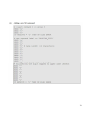
In the created program a simulation of the normal operation of the support pole will be
made: The module will be continuously trying to recognize the trigger word with a timeout of
5 seconds, if it is recognized, the module will ask then for any of the commands taught
previously. The program will print on screen everything the module does, asking for trigger
words, orders recognized, errors, but in a more user friendly way, not with simple characters.
This program example is included in appendix D, and as an attachment [11].
42
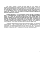
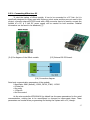
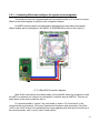
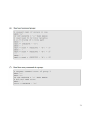
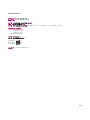
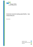
5.2.7.- Connecting VRbot and configure the system to work together
The serial port has been programmed and the module works, so it is time to connect
VRbot to the climb support to add the voice recognition feature.
As UART0 is being used for programming, debugging and supervising the system,
VRbot module will be connected to the UART1 of AT90CAN128 as show in the figure ().
(5.7) VRbot-PCB Connection diagram
After all the connections have been made, microcontroller has to be prepared to read
its UART1 on demand, so it has to be configured in a similar way as UART0 is. This can be
easily done in the source code file main.c.
It is recommended to “export” the code made in section 5.2.6 and test it in the
microcontroller environment. Of course, libraries and functions used previously of the files
rs232.c and rs232.h have to be substituted by those regarding the serial port connections in
the microcontroller, uart.c, uart.h, uart2.c and uart2.h.
43
5.2.8.-Implementation of voice recognition instructions in the program code
In the previous section it was achieved getting the VRbot module working with the
support pole microcontroller. So finally, voice recognition capabilities can be added to the
system. To separate the manual control from the automatic control, voice recognition will only
be implemented in auto mode, and will work together with the buttons in this mode.
The code is similar to the code of the PC example in section 5.2.6., and the algorithm
used will be the following:
1) Initialize VRbot when the climb support program is turned on.
2) In the main routine, give the proper commands to start recognition of the trigger word
continuously. While doing this, auto mode works as usual with the control pad.
3) If in AUTO mode and the trigger word is recognized, the module will ask for a valid
instruction then. If the trigger word is not recognized, go back to step 2.
4) If the instruction is recognized successfully, the desired action will be carried out by the
robot. Whether the instruction is recognized or not, go back to step 2.
5.2.9.- Making it work all together
The algorithm implemented previously in 5.2.8 is functional. However, a change has to
be made in the voice recognition system to make it work safer. A flaw of the VRbot module
operation when recognizing trigger words was encountered during the first tests of the
complete system: Voice recognition patterns for trigger words are too loose. This is a problem
because it causes a lot of false recognitions for trigger words. That is, the user says, for
example, “function”, but trigger word “instruction” is recognized instead. This cannot be
solved changing the code. It is not possible to change the “hardness” of the recognition
patterns for trigger words, as it is for commands stored in other wordsets .
The solution to this problem was to teach the word “instruction” to the module and
store it in a command wordset (wordset 4) different for the one used for the other
commands. The program will ask for commands in wordset 4, being the only one command in
the wordset the word “instruction”. If successfully recognized, it will ask then for commands
in wordset 1 (English commands). As the recognition level for SD commands is set to “hard”,
false recognitions disappear.
44
6. Final tests
After all the implementations have been done, some final tests are needed to see if
this thesis has met its purpose in improving the original prototype. Each and every of the new
functions and fixes implemented in this project have been extensively tested.
6.1.- Testing manual & auto mode
All the improvements made in both modes over the original prototype work properly. In
manual mode, manual control of the tightening, servo control and collision detection have
been implemented successfully.
In auto mode, the tightening/loosening has been implemented, as well as collision
detection. Movements can now be stopped and modified on demand, so the user does not
have to wait for an instruction to be carried out successfully to give another command to the
system.
One of the errors of the original prototype has not been solved, though. The
movement when tightening/loosening is still asymmetrical. The support pole tightens
correctly, but when loosening, it does not recover its original position. Usually it stops earlier,
and the manual loosening has to be used instead to get it back. This problem has been
studied but cannot be solved in the prototype as it is just by changing the code. This error is
caused by a malfunction of the tightening motor. The motor has been tested with a DC power
supply and monitored using multimeters and an oscilloscope and it does not work well. When
the support pole is loosening, it does not loosen completely, even if the signal for it is
received. Many times it needs signal pulses, that is, loosen it a bit, stop, loosen another bit,
stop, and so on.
It is also needed to mention that the accelerometer trigger values used for collision
detection are quite tight. Leaning the pole a bit can stop any instruction from being carried
out successfully by the system. While this is in general a good feature, it has some negative
effects in auto mode, sometimes stopping the support while moving from one position to
another (i.e. when going from position “home” to position “chair”).
6.2.- Testing voice recognition
Voice recognition has been implemented in this project. It is needed, then, to
determine its functionality. After testing it at 2 meters range, the following conclusion can
be extracted:
− Recognition is accurate, there are no “false recognitions”. This is especially
45
important for the trigger word, as it is not recognized in a normal conversation.
− Approximately 90% recognition success when the support pole is static. Recognition
patterns are really tight, spoken commands are not always recognized.
− Decreased recognition success when the support pole is moving. Due to the noise of
both tightening/loosening and leftwards/rightwards motors, and the microphone
being so near to them. This problem can be partially solved by speaking louder.
− Dramatically decreased recognition success when the user giving the commands is
different to the user who trained the system. Speaker Dependent commands, those
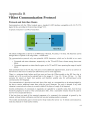
used in this project, are really like that, speaker dependent.
− Voice recognition is done in auto mode, but when in manual mode, the system still
continues recognizing commands. Usually this is not a problem, but if a command is
recognized in manual mode, and then the user switches to auto mode, this command
will be carried out.
− The recognition success improves, though, if the language used for it is Spanish or
Finnish, as they are languages easier to pronounce and less prone to be affected by
the original mother language of the user. It cannot be ignored when testing voice
recognition that the VRbot module was taught by a Spanish person, and the spoken
English does not sound exactly the same as the English of a Finn (as were the people
who helped with the test of the system).
6.3.- Initialization problems
Along the whole project a persistent error has been detected. This error was also
present in the prototype. The microcontroller does not always initialize well. Two problems
have been detected during the initialization:
- When loading the code to the microcontroller, the system automatically starts working, but
the values of the Y axis of the accelerometer change a lot. This error happens every time the
code is loaded, and it seems an error related to the I2C communication protocol, or the
LIS3LV02 driver used in the system (this driver is a custom driver). The error is automatically
solved if the system is shut down and then turned on again.
- The program does not always execute the while(1) loop in the main() function at the
first time. It is a strange error, as in main() the motors, as well as the state machine
interrupt are initialized. The system, then, starts its usual operation, but, as the voice
recognition subroutine is done in the while(1) loop inside main(), voice recognition
does not work. It is even stranger that during its normal operation suddenly the system
enters in the loop and voice recognition starts. This is done at random, sometimes starting
after a few seconds and sometimes after a minute or two. The system was also tested
without interrupts (thus, no state machine), and at a different frequency of the interrupts, to
see if this error was related to an overwhelmed microcontroller, but the same malfunctioning
still happened. This error does not happen if the code is loaded and the system not restarted,
but this creates a conflict with the error of the accelerometer values previously commented.
46
7. Conclusions and future work
Conclusions
As the final tests show, many improvements have been successfully implemented.
However, some other improvements are needed for a proper operation of the prototype at
this stage of development:
- Replace the tightening/loosening motor:
This motor does not work properly and it is not safe for the support pole to use it. The
problem cannot be fixed, either. In addition, this motor is quite noisy, and this creates a
conflict with the voice recognition, as well as not being user friendly. The noise problem is
also present in the other motor as well.
- Sound feedback in voice recognition:
As it is now, a PC is needed for monitoring the operation for voice recognition. The
user does not know if the trigger word, or any other command, is recognized or not if a PC is
not being used (unless both recognitions are successful and the result visible). This, of
course, is not acceptable out of the development environment.
- Consider an improved recognition system, or the implementation of an easy to use built-in
teach function in the system. The device has a big failure rate recognizing other users'
commands. This problem is encountered only using SD commands, not SI, so maybe in the
future, with a firmware update, the behavior of VRbot module will improve. If this does not
happen, maybe using a more complex module will be the better solution.
- Fix initialization errors commented in 6.3. They are not acceptable out of the development
environment.
Future work
The prototype is still at an early stage of development. There is a lot of work to be
done in further improvements, as well as enhancing already implemented functionalities. At
the moment the prototype usefulness is limited, and certainly a polishing work is needed
(both in aesthetic and functional terms) before it can possibly get out the development
environment and reach the market. But clearly an evolution of the support pole would be
welcomed in hospitals, nursing homes and private homes altogether.
The field of socially assistive robotics is expected to reach the mass market in the
future. It is important, then, to develop new robots and devices to compete in the market.
The versatility, users' acceptance, as well as the cost of these products has to be the key of
future developments.
47
48
8. DVD Attachments
[1] PIM3605 Intelligent Control Module datasheet
[2] PIM3605 User's Guide
[3] AT90CAN128 datasheet
[4] LIS3L02 Accelerometer datasheet
[5] Prototype's original code
[6] Loading the code on the microcontroller: Bootloader (*)
[7] VRbot datasheet
[8] VRbot users guide
[9] VRbot serial protocol (*)
[10] Serial port programming libraries
[11] Serial port programming example (*)
[12] Final code (used in the final tests)
[13] Final commented code (*)
[14] Video presentation of the support pole
[15] VRbot GUI 1.1.3
[16] HyperTerminal Private Edition 6.3
(*) Also in the appendix
49
50
9. References
(1)
“The Engineering Handbook of Smart Technology for Aging, Disability and
Independence”; Helal, Mokhtari and Abdulrazak; 2008.
(2)
“Defining Socially Assistive Robotics”. David Feil-Seifer and Maja J. Mataric. Interaction
Laboratory. University of Southern California. In proceedings of the 2005 IEEE 9th
International Conference on Rehabilitation Robotics June 28 – July 1, 2005, Chicago,
IL, USA. http://cres.usc.edu/pubdb_html/files_upload/442.pdf
(09/01/2010)
(3)
Technosoft web page
http://www.technosoftmotion.com/index.php (09/01/2010)
(4)
Technosoft PIM3605 Information, datasheet and user's guide
http://www.technosoftmotion.com/products/OEM_PROD_PIM3605.htm (09/01/2010)
(5)
Atmel web page
http://www.atmel.com/ (09/01/2010)
(6)
Atmel AT90CAN128 Information and datasheet
http://www.atmel.com/dyn/Products/product_card.asp?part_id=3388 (09/01/2010)
(7)
LIS3L02 datasheet
http://www.chipdocs.com/datasheets/datasheet-pdf/SGSThomsonMicroelectronics/LIS3L02.html (09/01/2010)
(8)
Ceilbot project
http://autsys.tkk.fi/en/Ceilbot (09/01/2010)
(9)
VeeaR web page
http://vee-ar.com/ (09/01/2010)
(10)
VRbot information and datasheet
http://www.veear.eu/Products/VRbot.aspx (09/01/2010)
(11)
VRbot GUI (Download)
http://www.veear.eu/LinkClick.aspx?fileticket=KZULbeOqvCM
%3d&tabid=220&mid=626 (09/01/2010)
(12)
VRbot User's Guide (Download)
http://www.veear.eu/LinkClick.aspx?fileticket=VowGK1u9rRc
%3d&tabid=220&mid=620 (09/01/2010)
51
(13)
VRbot protocol (Download)
http://www.veear.eu/LinkClick.aspx?fileticket=gJhfDlDWpC8%3d&tabid=220&mid=626
(09/01/2010)
(14)
Serial port protocol
http://en.wikipedia.org/wiki/Serial_port (09/01/2010)
(15)
HyperTerminal
http://www.hilgraeve.com/htpe/download.html (09/01/2010)
(16)
RS-232 C/C++ Libraries
http://www.teuniz.net/RS-232/ (09/01/2010)
(17)
AVRdude
http://www.bsdhome.com/avrdude/ (09/01/2010)
(18)
Eclipse C/C++ IDE
http://www.eclipse.org/ (09/01/2010)
(19)
AVR Eclipse plug-in
http://avr-eclipse.sourceforge.net/wiki/index.php/The_AVR_Eclipse_Plugin
(09/01/2010)
(20)
Embarcadero RAD Studio 2010
https://downloads.embarcadero.com/free/rad_studio (09/01/2010)
(21)
“A book on C”; Kelley and Pohl; 1990.
52
Appendix A
Loading the code on the microcontroller:
Software needed and Bootloader
This appendix is a small tutorial of how to load the code written to the microcontroller
using serial port communication.
A.1) Software needed
In
packages
−
−
−
−
order to program the microcontroller, it is required to have several
first, listed below:
Linux OS
Eclipse C/C++ IDE
AVR Eclipse Plug-In
AVRdude
software
Linux/Unix OS
This project has been done under Linux Ubuntu 9.04 OS, but any Debian based Linux
OS should serve as well. It may work under other operating systems, but it has not been
tested.
AVRdude
AVRdude is a GPL software package that allows machines running under
Linux/Windows environments to load/unload the code to several electronic devices.
To get it installed (using Ubuntu OS), the following code has to be introduced in the console
(administrator privileges are required):
user@user-pc:~$ sudo apt-get install avrdude
Eclipse C/C++ IDE
Eclipse C/C++ IDE is a powerful GPL development tool for programmers, able to
manage and debug large projects quite easily. The program can be downloaded from its
official web page:
http://www.eclipse.org/cdt/
AVR Eclipse Plug-In
To recognize the libraries and instructions used by AVR using Eclipse, it is needed to
get the AVR Eclipse plug-in. Detailed instructions on how to get the plug-in are in the web
page:
http://avr-eclipse.sourceforge.net/wiki/index.php/The_AVR_Eclipse_Plugin
53
A.2) Bootloader
The microcontroller and its PCB have a built-in bootloader. With this bootloader and
having all the software tools listed above, any code can be loaded on the microcontroller. To
achieve this, these are the steps to be done.
Compile the program with “make”
Though the program has been written with Eclipse, compiling it has to be done from
the console. A quite complex makefile has to be written and then, to compile the program,
introduce “make” in the console. When executed, information about the memory usage of the
device will appear. See below:
user@user-pc:~/climbsupportpole$ make
... (Compiling information, errors, warnings etc.)
AVR Memory Usage
---------------Device: at90can128
Program:
17236 bytes (13.2% Full)
(.text + .data + .bootloader)
Data:
397 bytes (9.7% Full)
(.data + .bss + .noinit)
The makefile of the project is included in appendix B. To know how this makefile has
to be written for AVRdude to recognize the code in it, it is recommended to read AVRdude
user's guide:
http://www.nongnu.org/avrdude/user-manual/avrdude.html
Put the microcontroller in bootloader mode
To charge the code to the microcontroller, it is needed first to put it in bootloader
mode. There are two visible buttons in the AT90CAN128's PCB used to do this: reset button
and loader button. See figure (A.1)
To put the microcontroller in bootloader mode, the following actions have to be done in
strict order:
1)
2)
3)
4)
Press (and maintain pressed) reset button.
Press (and maintain pressed) loader button.
Unpress the reset button.
Unpress loader button.
After doing this, the microcontroller will enter in bootloader mode and the code can be
54
loaded.
(A.1) Location of the reset and loader buttons in the microcontroller PCB
Loading the code
When the device is in bootloader mode, to load the code it is needed to connect the
PCB to the PC using serial connection (the PCB has a DB9 connector), and then introduce the
following instruction in the console (this code is also included in the makefile):
user@user-pc:~$ avrdude -c avr911 -P /dev/ttyUSB1 -b 115200 -p
at90can128 -U flash:w:main.hex:i
AVRdude should then answer information related to the program download:
Connecting to programmer: .
Found programmer: Id = "AVRBOOT"; type = S
… … … …
… … … … (Information about the download progress)
… … … …
avrdude: verifying ...
avrdude: 17108 bytes of flash verified
avrdude done.
Thank you.
Resetting the microcontroller
After loading the code, the program will start working, but until the initialization errors
55
listed in 6.3 are fixed, it is needed to turn off and on the device to restart, not just reset the
system by pressing the PCB button.
Supervising the support pole
To supervise the operation of the program in the console through the serial port,
introduce the following code in the console:
user@user-pc:~$screen /dev/ttyUSB1
HELLO!
Initializing device
INIT DRIVE
INIT DRIVE OK
NOT TIGHTENED
GOING HOME...
AT HOME
AUTO
56
Appendix B
Makefile of the system program
This makefile was originally developed by Teemu Kuusisto, being modified accordingly
with the renaming of the files, as well as the new added files.
###############################################################################
# Makefile for the support pole project
###############################################################################
## General Flags
PROJECT = main
MCU = at90can128
TARGET = main.elf
CC = avr-gcc
#avr-gcc.exe
FCPU=16000000
## Options common to compile, link and assembly rules
COMMON = -mmcu=$(MCU) -DF_CPU=$(FCPU)UL
## Compile options common for all C compilation units.
CFLAGS = $(COMMON)
CFLAGS += -Wall -gdwarf-2 -std=gnu99 -Os -funsigned-char -funsigned-bitfields fpack-struct -fshort-enums
CFLAGS += -MD -MP -MT $(*F).o -MF dep/$(@F).d
## Assembly specific flags
ASMFLAGS = $(COMMON)
ASMFLAGS += $(CFLAGS)
ASMFLAGS += -x assembler-with-cpp -Wa,-gdwarf2
## Linker flags
LDFLAGS = $(COMMON)
LDFLAGS += -Wl,-Map=main.map
## Intel Hex file production flags
HEX_FLASH_FLAGS = -R .eeprom
HEX_EEPROM_FLAGS = -j .eeprom
HEX_EEPROM_FLAGS += --set-section-flags=.eeprom="alloc,load"
HEX_EEPROM_FLAGS += --change-section-lma .eeprom=0 --no-change-warnings
## Objects that must be built in order to link
OBJECTS = main.o statemachine.o leds.o interrupts.o motor.o slidepotentiometer.o
accelerometer.o lis3lv02_driver.o a2d.o i2c.o uart2.o rprintf.o buffer.o can_drv.o
can_lib.o canproto.o voicerecon.o
## Objects explicitly added by the user
LINKONLYOBJECTS =
## Build
all: $(TARGET) main.hex main.eep main.lss size
flash: main.hex
avrdude -c avr911 -P COM1 -b 115200 -p at90can128 -U flash:w:main.hex:i
57
flashlinux:
avrdude -c avr911 -P /dev/ttyUSB1 -b 115200 -p at90can128 -U
flash:w:main.hex:i
## Compile
main.o: main.c
$(CC) $(INCLUDES) $(CFLAGS) -c
$<
statemachine.o: statemachine.c
$(CC) $(INCLUDES) $(CFLAGS) -c
$<
leds.o: leds.c
$(CC) $(INCLUDES) $(CFLAGS) -c
$<
interrupts.o: interrupts.c
$(CC) $(INCLUDES) $(CFLAGS) -c
$<
motor.o: motor.c
$(CC) $(INCLUDES) $(CFLAGS) -c
$<
slidepotentiometer.o: slidepotentiometer.c
$(CC) $(INCLUDES) $(CFLAGS) -c $<
accelerometer.o: accelerometer.c
$(CC) $(INCLUDES) $(CFLAGS) -c
$<
lis3lv02_driver.o: lis3lv02_driver.c
$(CC) $(INCLUDES) $(CFLAGS) -c
$<
a2d.o: a2d.c
$(CC) $(INCLUDES) $(CFLAGS) -c
$<
i2c.o: i2c.c
$(CC) $(INCLUDES) $(CFLAGS) -c -fgnu89-inline $<
uart2.o: uart2.c
$(CC) $(INCLUDES) $(CFLAGS) -c
$<
rprintf.o: rprintf.c
$(CC) $(INCLUDES) $(CFLAGS) -c
$<
buffer.o: buffer.c
$(CC) $(INCLUDES) $(CFLAGS) -c
$<
canproto.o: canproto.c
$(CC) $(INCLUDES) $(CFLAGS) -c
$<
can_lib.o: can_lib.c
$(CC) $(INCLUDES) $(CFLAGS) -c
$<
can_drv.o: can_drv.c
$(CC) $(INCLUDES) $(CFLAGS) -c
$<
voicerecon.o: voicerecon.c
$(CC) $(INCLUDES) $(CFLAGS) -c
$<
##Link
$(TARGET): $(OBJECTS)
$(CC) $(LDFLAGS) $(OBJECTS) $(LINKONLYOBJECTS) $(LIBDIRS) $(LIBS) -o
$(TARGET)
%.hex: $(TARGET)
avr-objcopy -O ihex $(HEX_FLASH_FLAGS)
$< $@
58
%.eep: $(TARGET)
-avr-objcopy $(HEX_EEPROM_FLAGS) -O ihex $< $@ || exit 0
%.lss: $(TARGET)
avr-objdump -h -S $< > $@
size: ${TARGET}
@echo
@avr-size -C --mcu=${MCU} ${TARGET}
## Clean target
.PHONY: clean
clean:
-rm -rf $(OBJECTS) main.elf dep/* main.hex main.eep main.lss main.map
## Other dependencies
-include $(shell mkdir dep 2>/dev/null) $(wildcard dep/*)
59
60
61
62
63
64
65
66
67
68
69
70
71
72
73
74
Appendix D
Serial port C/C++ programming example
This sample code has been used to test the VRbot module in a serial programming PC
environment. It uses two GPL files, rs-232.c and rs-232.h developed by Teunis van Beelen.
This program was compiled, executed and tested with Embarcadero RAD Studio 2010 (Trial
Version), under Windows Vista environment.
Header file voicerecon.h
/* The following definitions help to work with the VRBot module environment
Further details of the VRbot commands and responses can be found in
the Appendix C of this project */
#define
#define
#define
#define
#define
#define
#define
#define
#define
#define
#define
#define
#define
#define
#define
#define
#define
#define
#define
#define
#define
#define
#define
#define
#define
START_RECOGNITION 'd'
TRIGGER 'A'
INSTRUCTION 'B'
MOVE_LEFT 'A'
MOVE_RIGHT 'B'
STOP 'C'
TIGHTEN 'D'
GO_HOME 'E'
GO_TO_BED 'F'
GO_TO_CHAIR 'G'
CLOSE 'H'
ACK ' '
START_RECON 'd'
TRIGGER_RECON 'A'
ORDER_RECON 'B'
TIMEOUT 't'
RECON_OK 'r'
ASK_ID 'x'
ID0 'A'
WAKE 'b'
LANGUAGE_SET 'l'
ENGLISH 'A'
OK 'o'
FIVE_SECONDS 'F'
SET_TIMEOUT 'o'
/* Declaration of the functions used */
void initialization(unsigned char *buf);
void SendInstruction (unsigned char instruction, unsigned char *buf);
int GetInstruction(unsigned char *buf);
Source file voicerecon.c
#include "VoiceRecon.h"
#include "rs-232.h"
/* This program has been created as a test of the VRbot module under a PC
environment. It communicates with the device using the serial port.
The program asks the user to say the trigger word 'instruction'.
If the word is not recognized, will print the error, and if the user
75
does not speak within 5 seconds, will print 'timeout'. If the word is
recognized, it will ask for any of the commands. If any of the
commands is recognized, it will print it, if not, it would be the same as
for the trigger word. Either way it will start again asking for the
trigger word. The only way of ending the program is to give it the
command 'close'.In that case, it will close itself.
*/
int main (void)
{
char info;
int i, response;
int close=0;
unsigned char *buf;
initialization(buf);
printf("\nSTARTING RECOGNITION\n");
}
while (close!=1){
printf("Trigger Word: ");
SendByte(0, START_RECON);
SendInstruction(TRIGGER_RECON,buf);
if (*buf==RECON_OK){
printf("ACCEPTED -- Instruction: ");
SendByte(0, START_RECON);
SendInstruction (ORDER_RECON,buf);
if (*buf==RECON_OK) {
SendInstruction (ACK,buf);
close=GetInstruction(buf);
} else if (*buf==TIMEOUT) {
printf("Timeout \n");
} else {
printf("Recognition failed\n");
}
} else if (*buf==TIMEOUT) {
printf("Timeout \n");
} else {
printf("Recognition failed\n");
}
}
/* Closing COM port 0 to avoid conflicts with other programs
that want to use it */
printf("\nClosing port 0: ");
CloseComport(0);
printf("CLOSED\n");
printf("Exiting program\n");
return 0;
/* initialization(unsigned char *buf)
*buf: Byte read from the serial port
This function opens the COM port 0 to establish communication
through the serial port and configures some features of the VRbot module*/
void initialization(unsigned char *buf)
{
int response,i;
i=0;
/* Opening COM port 0, and establishing the parameters of the serial port
communication as 8-bit data, 1-bit stop, no parity, 9600bd,
no flow control */
printf("Opening COM 0\n");
OpenComport(0,9600);
printf("Initializing device\n");
// Waking up device from low-power/saving mode
76
while (*buf != OK) {
SendInstruction (WAKE,buf);
if (i>=5) {
printf("ERROR: Failed to initialize device\n");
break;
}
i++;
}
// Ask firmware ID (It has to be '0')
SendInstruction(ASK_ID,buf);
if (*buf != ASK_ID) {
printf("ERROR: Cannot read device ID\n");
}
// Send ack and read status (expecting ID=0)
SendInstruction (ACK,buf);
if (*buf != ID0) {
printf("ERROR: Device ID doesn't match\n");
}
else {
printf("Device identified\n");
}
// Set language for Speaker Independent instructions (English)
SendByte(0,LANGUAGE_SET);
SendInstruction (ENGLISH,buf);
if (*buf != OK) {
printf("ERROR: Could not set default language for built-in
instructions (English)\n");
} else {
printf("Language set: English\n");
}
// Set timeout (5 seconds)
SendByte(0,SET_TIMEOUT);
SendInstruction (FIVE_SECONDS,buf);
if (*buf != OK) {
printf("ERROR: Timeout not set\n");
}
printf("Timeout set: 5 seconds\n");
printf("Device initialized\n");
}
/* SendInstruction (unsigned char instruction, unsigned char *buf)
instruction: Command (byte) sent to the device through the serial port
*buf: Byte read from the serial port buffer
This function sends an instruction to the device and then waits for
a response from it */
void SendInstruction (unsigned char instruction, unsigned char *buf)
{
int response=0;
SendByte(0, instruction);
while (response!=1)
{
response=PollComport(0, buf, 1);
}
}
/* GetInstruction(unsigned char *buf)
*buf: Byte read from the serial port buffer
This function gets the byte read from the device and translates the
response to a more friendly language
Always returns zero, save if the instruction 'close' is given
77
In that case it will return one and the main routine will end */
int GetInstruction(unsigned char *buf)
{
int close=0;
switch (*buf) {
case MOVE_LEFT:
printf("MOVING LEFT...\n");
break;
case MOVE_RIGHT:
printf("MOVING RIGHT...\n");
break;
case STOP:
printf("STOP\n");
break;
case TIGHTEN:
printf("TIGHTEN\n");
break;
case GO_HOME:
printf("GOING HOME\n");
break;
case GO_TO_BED:
printf("GOING TO BED\n");
break;
case GO_TO_CHAIR:
printf("GOING TO CHAIR\n");
break;
case CLOSE:
close=1;
break;
}
default:
;
}
return close;
78
Appendix E
Final code of the system program
In this appendix the code used for the system program is included. The table below
shows the files of the program, along with a general description of their purpose and
programmers. To compile the program the makefile included in appendix B is needed. Only
the files developed and written by Alvar Aalto University students for this project are printed.
The remaining files are general purpose generic files, not developed with this project in mind,
that can be obtained from Atmel or are GNU Public License Files.
F ile nam e(*)
F unctions / Devices m anaged
a2d.c /.h
accelerom eter.c /.h
av rlibdefs.h
av rlibty pes.h
buffer.c /.h
buzzer.c /.h
can_drv .c /.h
can_lib.c /.h
canproto.c /.h
config.h
global.h
i2c.c /.h
i2cconf.h
interrupts.c /.h
leds.c /.h
lis3l02.c /.h
lis3l02_driv er.c /.h
m ain.c
m otor.c /.h
rprintf.c /.h
slidepotentiom eter.c /.h
statem achine.c /.h
tim er.c /.h
uart.c /.h
uart2.c /.h
util.h
Analog to digital conv ersion libraries
Accelerom eter control routines
Definitions and m acros for Atm el AVR series
Ty pe definitions for Atm el AVR series
B uffer libraries used by the U ARTs
B uzzer (not used)
CAN driv ers for Atm el AT90CAN series
CAN function libraries for Atm el AT90CAN series
Modified CAN libraries for additional functions
G eneral sy stem definitions
Includes and definitions for Atm el AVR series
I2C protocol for Atm el AVR series
I2C protocol for Atm el AVR series
Interrupt for the state m achine subroutine
LEDs of the control pad
Accelerom eter driv ers for Atm el AVR series
Modified and im prov ed accelerom eter driv ers
Main routine
Tightening/Loosening m otor
rprintf function for Atm el AVR series
Sliding potentiom eter
State m achine of the sy stem program
Sy stem tim er function libraries
U ART driv er for Atm el AVR series
U ART driv er for Atm el AVR series
Standard useful definitions
Program m er(**)
P.S.
T.K . & J.L.
P.S.
P.S.
P.S.
T.K .
Atm el
Atm el
J.A.
T.K .
P.S.
P.S.
P.S.
T.K .
T.K .
P.S.
A.L.
T.K . & J.L.
T.K .
P.S.
T.K .
T.K . & J.L.
P.S.
P.S.
P.S.
T.K .
(*) Filenames
The code uses C source files (.c) and header files (.h). The majority of files are source
files with attached header files, this is noted as in the table as “.c /.h”
79
(**) Programmers
- A.L.: Antti Liesjärvi; Alvar Aalto University student, Automation & Systems department.
- Atmel: Atmel CAN files with copyright.
- J.A.: Johannes Aalto; Alvar Aalto University student, Automation & Systems department.
- J.L.: Jorge Latorre; University Carlos III of Madrid; Exchange student at Alvar Aalto
University, Automation & Systems Department; Writer of this project.
- T.K.: Teemu Kuusisto. Alvar Aalto University student, Automation & Systems Department;
Original developer of the support pole.
- P.S.: Pascal Stang; Atmel files under GNU Public License.
List of printed files
File name
main.c
statemachine.h
statemachine.c
accelerometer.h
accelerometer.c
voicerecon.h
voicerecon.c
motor.h
motor.c
leds.h
leds.c
interrupts.h
interrupts.c
slidepotentiometer.h
slidepotentiometer.c
lis3lv02driver.h
lis3lv02driver.c
canproto.h
canproto.c
global.h
util.h
Page
83
86
89
110
111
115
116
120
120
122
122
123
123
125
125
127
130
137
139
146
146
NOTE: This code has been in-file commented after the final tests. Any change has been
made in the code after the final tests, only comments. Just in case any error occurs when
compiling and testing this code, the same code tested is included as DVD attachment [12].
80
main.c
#define MAIN_C
/*
* main() routine initializes all the I/O of the microcontroller, as well as
* the devices attached to it. The voice recognition routine is executed here, but
* the remaining control of the system is done by the interrupt driven
* state_machine() function, in statemachine.c file
*/
#include
#include
#include
#include
#include
#include
#include
#include
#include
#include
#include
#include
#include
#include
#include
#include
#include
<avr/io.h>
<avr/interrupt.h>
<util/delay.h>
"util.h"
"motor.h"
"statemachine.h"
"leds.h"
"interrupts.h"
"i2c.h"
"lis3lv02_driver.h"
"slidepotentiometer.h"
"a2d.h"
"accelerometer.h"
"uart2.h"
"rprintf.h"
"canproto.h"
"voicerecon.h"
void init(void);
unsigned
volatile
volatile
volatile
char VRorder;
uint8_t canstate;
uint8_t state;
uint8_t next_state;
//ID of the MICROController
#define CANID 2
int main(void) {
// CAN initialization
caninit();
// Digital I/O initialization
init();
sei();
}
while (1)
{
// Starting voice recognition subroutine
VRorder=voicerecognition();
}
return 0;
void init(void) {
//Start Timer
timer_start();
// Port A (BUTTONS) initialization
//Buttons on terminal blocks
DDRA = 0x00;
//Data direction INPUT
PORTA = 0xFF;
//activate the pull-up resistor for buttons
81
// Port B (MOTOR) initialization
DDRB = 0xFF;
//data direction OUTPUT
cbi(PORTB,PB4);
//PB4 (OC4) - OC2A (PWM output),
cbi(MOTOR_PORT,MOTOR_DIRECTION);
//PB5 (OC3) - motor direction
sbi(MOTOR_PORT,MOTOR_ENABLE); //PB6 (OC2) - enable
// Port C (LEDS) initialization
DDRC = 0xFF;
//data direction OUTPUT
PORTC = 0x00;
//LEDS are grounded - 0 means off
// Port D initialization
PORTD = 0x00;
DDRD = 0x00;
// Port E initialization
DDRE = 0x00;
PORTE = 0xFF;
//activate the pull-up resistor for buttons
//Initialization of the PCB buttons and LED.
//Set output direction for led, see AT90CAN128 datasheet page 66
sbi(STATUSLED_DIRECTION,STATUSLED);
sbi(STATUSLED_PORT,STATUSLED);
/** Port F initialization*/
DDRF = 0xFF;
PORTF = 0x00;
// Data direction INPUT
cbi(POTENTIOMETER_DDR,POTENTIOMETER);
sbi(POTENTIOMETER_PORT,POTENTIOMETER);
// Port G initialization
PORTG = 0xFF;
DDRG = 0xFF;
TCCR1A = 0;
TCCR1B = 0;
TCCR1C = 0;
TCCR2A = 0;
//init_pwm(); -- Pulse Width Modulation is not being used in this version
// Initializing both UARTs
uartInit();
// UART0 used for rprintf function
rprintfInit(uart0SendByte);
// Initialization of the potentiometer, interrupts and accelerometer
init_potentiometer();
init_interrupt();
i2cInit();
lis_init();
lis_power_up();
}
// Initialization of the states in statemachine.c
next_state = 0;
goto_init_drive();
82
statemachine.h
#ifndef STATEMACHINE_H
#define STATEMACHINE_H
// Buttons in A port
//BLACK wire 1
#define BUTTON_CHAIR 0
//GRAY WIRE 1
#define BUTTON_BED 1
#define BUTTON_DOWN 1
//BLUE WIRE 1
#define BUTTON_HOME 2
#define BUTTON_UP 2
//YELLOW WIRE 1
#define BUTTON_RIGHT 3
//RED WIRE 1
#define BUTTON_LEFT 4
//RED WIRE 2
#define BUTTON_AUTO 5
//YELLOW wire 2
#define BUTTON_MANUAL 6
//GREEN WIRE 2
#define BUTTON_TIGHT_LOOSE 7
// Buttons in E port
//GREY WIRE 3
#define AT_HOME 6
//Button on the olimex board
#define ONBOARDBUTTON 5
// Port
#define
#define
#define
A buttons
BUTTON_PINA PINA
BUTTON_PORTA PORTA
BUTTON_DDRA DDRA
// Port
#define
#define
#define
E buttons
BUTTON_PORTE PORTE
BUTTON_PINE PINE
BUTTON_DDRE DDRE
// Available states in the state machine
#define STATE_NONE 0
#define STATE_LEFT 1
#define STATE_RIGHT 2
#define STATE_MANUAL 3
#define STATE_AUTO 4
#define STATE_TIGHTENED 5
#define STATE_TIGHTENING 6
#define STATE_LOOSENING 7
#define STATE_HOME 8
#define STATE_BED 9
#define STATE_CHAIR 10
#define STATE_AT_HOME 11
#define STATE_NOT_READY 12
#define STATE_INIT_DRIVE 13
#define STATE_MANUAL_TIGHTENING 14
#define STATE_MANUAL_LOOSENING 15
#define STATE_PUSH_LEFT 16
#define STATE_PUSH_RIGHT 17
#define STATE_MOVING_LEFT 18
#define STATE_MOVING_RIGHT 19
83
#define
#define
#define
#define
#define
#define
#define
NEXT_STATE_NONE 0
NEXT_STATE_HOME 1
NEXT_STATE_BED 2
NEXT_STATE_CHAIR 3
NEXT_STATE_MANUAL 4
NEXT_STATE_AUTO 5
NEXT_STATE_NOT_READY 6
// Definitions to use in combination with is_straight
#define STATIC 0
#define MOVING_LEFT 1
#define MOVING_RIGHT 2
#define PUSHING_LEFT 3
#define PUSHING_RIGHT 4
uint8_t
uint8_t
uint8_t
uint8_t
button_changedA(uint8_t button);
button_changedE(uint8_t button);
button_down_portA(uint8_t button);
button_down_portE(uint8_t button);
uint8_t
uint8_t
uint8_t
uint8_t
uint8_t
uint8_t
uint8_t
uint8_t
uint8_t
uint8_t
uint8_t
uint8_t
uint8_t
uint8_t
uint8_t
uint8_t
uint8_t
uint8_t
uint8_t
uint8_t
uint8_t
#endif
goto_none();
goto_auto();
goto_manual();
goto_left();
goto_right();
goto_tight();
goto_tightened();
goto_loose();
goto_home();
goto_bed();
goto_chair();
state_machine();
at_home();
goto_not_ready();
goto_init_drive();
goto_manual_tight();
goto_manual_loose();
goto_push_left();
goto_push_right();
goto_moving_right();
goto_moving_left();
84
statemachine.c
/*
* This file contains all the subroutines managing the large state machine of the
* system state_machine(int state) function is called by an interrupt (configured
* in interrupts.c) at a frequency of 1KHz approximately
*
* It is the main and most important function in the whole system:
* checks the state of the system inputs and outputs and manages all the user's
* instructions and system movement
*
*/
#include
#include
#include
#include
#include
#include
#include
#include
#include
#include
#include
#include
#include
<avr/io.h>
"statemachine.h"
"leds.h"
<util/delay.h>
"global.h"
"slidepotentiometer.h"
"motor.h"
"accelerometer.h"
"rprintf.h"
"interrupts.h"
"uart2.h"
"voicerecon.h"
"canproto.h"
// Voice Recognition order from the main routine
extern unsigned char VRorder;
/**Last
uint8_t
uint8_t
uint8_t
uint8_t
state of the buttons. 0 if button is down*/
button_stateA;
button_stateE;
buttons_changedA;
buttons_changedE;
static int previous_state=0;
int direction=0;
// Defines the moving way of the shaft motor
uint8_t tightening_time = 0;
uint8_t loosening_time = 0;
// Auto state = 1, Manual state = 2
uint8_t auto_or_manual_state=0;
// Returns the nonzero if specified button is pressed
uint8_t button_down_portA(uint8_t button) {
return ((~BUTTON_PINA) & (1 << button));
}
uint8_t button_down_portE(uint8_t button) {
return ((~BUTTON_PINE) & (1 << button));
}
// Below are defined all the functions that make transitions between states and
control the
// LEDs in the control pad
/* ----- Go to NONE state ----- */
uint8_t goto_none() {
led_on(LED_READY);
led_on(LED_ACTION);
state = STATE_NONE;
85
return 0;
}
/* ----- Go to AUTO state ----- */
uint8_t goto_auto() {
auto_or_manual_state = 1;
rprintf("AUTO\r\n");
led_on(LED_READY);
led_off(LED_ACTION);
state = STATE_AUTO;
return 0;
}
/* ----- Go to MANUAL state ----- */
uint8_t goto_manual() {
auto_or_manual_state = 2;
rprintf("MANUAL\r\n");
led_on(LED_READY);
led_off(LED_ACTION);
state = STATE_MANUAL;
return 0;
}
/* ----- Go to LEFT state ----- */
uint8_t goto_left() {
rprintf("MOVING LEFT...\r\n");
led_on(LED_ACTION);
led_off(LED_READY);
state = STATE_LEFT;
return 0;
}
/* ----- Go to RIGHT state ----- */
uint8_t goto_right() {
rprintf("MOVING RIGHT...\r\n");
led_on(LED_ACTION);
led_off(LED_READY);
state = STATE_RIGHT;
return 0;
}
/* ----- Go to TIGHTENING state ----- */
uint8_t goto_tight() {
timer_start();
rprintf("TIGHTENING\r\n");
led_on(LED_ACTION);
led_off(LED_READY);
state = STATE_TIGHTENING;
return 0;
}
/* ----- Go to TIGHTENED state ----- */
uint8_t goto_tightened() {
rprintf("TIGHTENED\r\n");
led_off(LED_ACTION);
led_on(LED_READY);
state = STATE_TIGHTENED;
return 0;
}
/* ----- Go to LOOSENING state ----- */
uint8_t goto_loose() {
timer_start();
rprintf("LOOSENING\r\n");
led_on(LED_ACTION);
86
led_off(LED_READY);
state = STATE_LOOSENING;
return 0;
}
/* ----- Go to HOME state ----- */
uint8_t goto_home() {
rprintf("GOING HOME\r\n");
led_on(LED_ACTION);
led_off(LED_READY);
state = STATE_HOME;
return 0;
}
/* ----- Go to BED state ----- */
uint8_t goto_bed() {
rprintf("GOING TO THE BED\r\n");
led_on(LED_ACTION);
led_off(LED_READY);
state = STATE_BED;
return 0;
}
/* ----- Go to CHAIR state ----- */
uint8_t goto_chair() {
rprintf("GOING TO THE CHAIR\r\n");
led_on(LED_ACTION);
led_off(LED_READY);
state = STATE_CHAIR;
return 0;
}
/* ----- Go to AT HOME state ----- */
uint8_t at_home() {
rprintf("AT HOME\r\n");
led_on(LED_ACTION);
led_on(LED_READY);
state = STATE_AT_HOME;
return 0;
}
/* ----- Go to NOT READY state ----- */
uint8_t goto_not_ready() {
timer_start();
led_on(LED_ACTION);
led_on(LED_READY);
state = STATE_NOT_READY;
return 0;
}
/* ----- Go to INIT DRIVE state ----- */
uint8_t goto_init_drive() {
}
timer_start();
rprintf("HELLO!\r\n");
led_on(LED_ACTION);
led_on(LED_READY);
state = STATE_INIT_DRIVE;
return 0;
/* ----- Go to MANUAL TIGHTENING state ----- */
uint8_t goto_manual_tight() {
rprintf("MANUAL TIGHTENING\r\n");
led_on(LED_ACTION);
87
led_off(LED_READY);
state = STATE_MANUAL_TIGHTENING;
return 0;
}
/* ----- Go to MANUAL LOOSENING state ----- */
uint8_t goto_manual_loose() {
rprintf("MANUAL LOOSENING\r\n");
led_on(LED_ACTION);
led_off(LED_READY);
state = STATE_MANUAL_LOOSENING;
return 0;
}
/* ----- Go to PUSH LEFT (SERVO) state ----- */
uint8_t goto_push_left(){
rprintf("PUSHING LEFT\r\n");
led_on(LED_ACTION);
led_off(LED_READY);
state = STATE_PUSH_LEFT;
return 0;
}
/* ----- Go to PUSH RIGHT (SERVO) state ----- */
uint8_t goto_push_right(){
rprintf("PUSHING RIGHT\r\n");
led_on(LED_ACTION);
led_off(LED_READY);
state = STATE_PUSH_RIGHT;
return 0;
}
/* ----- Go to MOVING RIGHT (Voice recognition only) state ----- */
uint8_t goto_moving_right() {
rprintf("MOVING RIGHT...\r\n");
led_on(LED_ACTION);
led_off(LED_READY);
state = STATE_MOVING_RIGHT;
return 0;
}
/* ----- Go to MOVING LEFT (Voice recognition only) state ----- */
uint8_t goto_moving_left() {
rprintf("MOVING LEFT...\r\n");
led_on(LED_ACTION);
led_off(LED_READY);
state = STATE_MOVING_LEFT;
return 0;
}
// Interrupt-driven state machine ruling the system:
// It is a large switch loop checking the current state of the system first, and
// then checks the I/O
uint8_t state_machine() {
switch (state) {
// First state of the state machine. Initializes the drive controller
case STATE_INIT_DRIVE:
rprintf("INIT DRIVE\r\n");
drive_init();
//wait 2 seconds for initializing drive
while(time()<32000) {
88
timer_run();
}
rprintf("INIT DRIVE OK\r\n");
goto_not_ready();
break;
// Loosen the support and going home
case STATE_NOT_READY:
loosen();
//wait 10 seconds
while(time()<64000) {
timer_run();
}
rprintf("NOT TIGHTENED\r\n");
rprintf("GOING HOME...\r\n");
//defines acc
drive_write_param32(CODE_CACC, ACC_1);
//set speed mode 1
drive_write_param32(CODE_MODE_TYPE, CODE_SP1);
//set command speed to the LEFT
drive_write_paramf(CODE_CSPD, 80);
//start motion
drive_send_command(CODE_UPD);
//until at home
while (!button_down_portE(AT_HOME));
//stop ceiling motor
drive_send_command(CODE_STOP);
//reset faults
drive_send_command(CODE_FAULTRESET);
//set actual position = 0
drive_write_param32(CODE_SAP, 0);
rprintf("AT HOME\r\n");
goto_none();
break;
break;
// Checking mode switch and configuring the motor
case STATE_NONE:
if (button_down_portA(BUTTON_MANUAL)) {
//reset faults
drive_send_command(CODE_FAULTRESET);
//defines acc
drive_write_param32(CODE_CACC, ACC_1);
//update values
drive_send_command(CODE_UPD);
goto_manual();
break;
} else if (button_down_portA(BUTTON_AUTO)) {
//reset faults
drive_send_command(CODE_FAULTRESET);
//defines acc
drive_write_param32(CODE_CACC, ACC_01);
//defines speed
drive_write_paramf(CODE_CSPD, 130);
//update values
89
drive_send_command(CODE_UPD);
goto_auto();
break;
}
break;
// Manual state --- Buttons used: Left, Right, Tightening, Manual Tightening
// and Manual Loosening. It also checks accelerometer values for servo
// control
case STATE_MANUAL:
previous_state=state;
// Check if any of the listed buttons are pressed and go to the
desired
// state
if (button_down_portA(BUTTON_LEFT)) {
goto_left();
break;
} else if (button_down_portA(BUTTON_RIGHT)) {
goto_right();
break;
} else if (button_down_portA(BUTTON_TIGHT_LOOSE)) {
goto_tight();
break;
} else if (button_down_portA(BUTTON_AUTO)) {
goto_none();
break;
} else if (button_down_portA(BUTTON_UP)) {
goto_manual_loose();
break;
} else if (button_down_portA(BUTTON_DOWN)) {
goto_manual_tight();
break;
/* ----- Check if it is being pushed (servo control) ----- */
} else if (is_straight(PUSHING_LEFT)) {
goto_push_left();
break;
} else if (is_straight(PUSHING_RIGHT)) {
goto_push_right();
break;
}
break;
// Auto state --- Buttons used: Home, Bed, Chair and Tightening.
// It also checks voice recognition commands (VRorder)
case STATE_AUTO:
if (button_down_portA(BUTTON_MANUAL)) {
goto_none();
break;
} else if ((button_down_portA(BUTTON_HOME))||(VRorder==VR_GO_HOME)) {
goto_home();
break;
} else if ((button_down_portA(BUTTON_BED))||(VRorder==VR_GO_TO_BED)) {
goto_bed();
break;
} else if
((button_down_portA(BUTTON_CHAIR))||(VRorder==VR_GO_TO_CHAIR)) {
goto_chair();
break;
} else if (VRorder==VR_MOVE_LEFT) {
90
goto_moving_left();
break;
} else if (VRorder==VR_MOVE_RIGHT) {
goto_moving_right();
break;
} else if
((button_down_portA(BUTTON_TIGHT_LOOSE))||(VRorder==VR_TIGHTEN)){
goto_tight();
break;
}
break;
// Moving left in manual mode while Left button is pressed and the movement
// limits not reached
case STATE_LEFT:
if (is_straight(MOVING_LEFT)) {
//set speed mode 1
drive_write_param32(CODE_MODE_TYPE, CODE_SP1);
//set command speed to the LEFT
drive_write_paramf(CODE_CSPD, 80);
//start motion
drive_send_command(CODE_UPD);
if (!button_down_portA(BUTTON_LEFT) || button_down_portE(AT_HOME)
|| drive_read_param32(ASK_APOS) > 1000) {
//button is not pressed anymore, STOP the ceiling motor
drive_send_command(CODE_STOP);
goto_manual();
break;
}
} else {
drive_send_command(CODE_STOP);
goto_manual();
break;
}
break;
// Moving right in manual mode while Right button is pressed and the
movement
// limits not reached
case STATE_RIGHT:
if (is_straight(MOVING_RIGHT)) {
//set speed mode 1
drive_write_param32(CODE_MODE_TYPE, CODE_SP1);
//set command speed to the RIGHT
drive_write_paramf(CODE_CSPD, -60);
//start motion
drive_send_command(CODE_UPD);
if (!button_down_portA(BUTTON_RIGHT) ||
drive_read_param32(ASK_APOS) <= -6250000 ) {
//button is not pressed anymore, STOP the ceiling motor
drive_send_command(CODE_STOP);
goto_manual();
break;
}
}
else
{
drive_send_command(CODE_STOP);
goto_manual();
91
break;
}
break;
/* VR instruction: Move left. The support will only stop if MANUAL mode is
selected, it is given a different VR or AUTO instruction or it reaches the
boundaries */
case STATE_MOVING_LEFT:
{
if (is_straight(MOVING_LEFT)) {
//set speed mode 1
drive_write_param32(CODE_MODE_TYPE, CODE_SP1);
//set command speed to the LEFT
drive_write_paramf(CODE_CSPD, 80);
//start motion
drive_send_command(CODE_UPD);
{
//check if home, bed or chair is pressed (or manual mode)
if (button_down_portA(BUTTON_MANUAL)) {
drive_send_command(CODE_STOP);
goto_none();
break;
}
else if ((button_down_portA(BUTTON_HOME))||(VRorder==VR_GO_HOME))
//start to move the ceiling motor to position HOME
drive_send_command(CODE_STOP);
goto_home();
break;
} else if
((button_down_portA(BUTTON_BED))||(VRorder==VR_GO_TO_BED)) {
//start to move the ceiling motor to position BED
drive_send_command(CODE_STOP);
goto_bed();
break;
} else if
((button_down_portA(BUTTON_CHAIR))||(VRorder==VR_GO_TO_CHAIR)) {
//start to move the ceiling motor to position CHAIR
drive_send_command(CODE_STOP);
goto_chair();
break;
} else if (VRorder==VR_MOVE_RIGHT){
drive_send_command(CODE_STOP);
goto_moving_right();
break;
/* If VR or manually order to start tightening, stop the
ceiling motor and start tightening */
} else if
((VRorder==VR_TIGHTEN)||(button_down_portA(BUTTON_TIGHT_LOOSE))){
drive_send_command(CODE_STOP);
goto_tight();
break;
/* If VR ordered to stop or it reaches the limits, stop the
ceiling motor */
} else if ((drive_read_param32(ASK_APOS) >
1000)||(VRorder==VR_STOP)) {
drive_send_command(CODE_STOP);
goto_auto();
break;
}
} else {
// The support is leaned, don't move
drive_send_command(CODE_STOP);
92
goto_auto();
break;
}
break;
}
case STATE_MOVING_RIGHT:
{
/* VR instruction: Move right. The support will only stop if MANUAL
mode is selected, it is given a different VR or AUTO instruction or
it reaches the boundaries */
if (is_straight(MOVING_RIGHT))
{
// Set speed mode 1
drive_write_param32(CODE_MODE_TYPE, CODE_SP1);
// Set command speed to the RIGHT
drive_write_paramf(CODE_CSPD, -60);
// Start motion
drive_send_command(CODE_UPD);
{
// Check if home, bed or chair is pressed (or manual mode)
if (button_down_portA(BUTTON_MANUAL)) {
drive_send_command(CODE_STOP);
goto_none();
break;
}
else if ((button_down_portA(BUTTON_HOME))||(VRorder==VR_GO_HOME))
// Start to move the ceiling motor to position HOME
drive_send_command(CODE_STOP);
goto_home();
break;
} else if
((button_down_portA(BUTTON_BED))||(VRorder==VR_GO_TO_BED)) {
// Start to move the ceiling motor to position BED
drive_send_command(CODE_STOP);
goto_bed();
break;
} else if
((button_down_portA(BUTTON_CHAIR))||(VRorder==VR_GO_TO_CHAIR)) {
// Start to move the ceiling motor to position CHAIR
drive_send_command(CODE_STOP);
goto_chair();
break;
} else if (VRorder==VR_MOVE_LEFT){
drive_send_command(CODE_STOP);
goto_moving_left();
break;
/* If VR or manually order to start tightening, stop the
ceiling motor and start tightening */
} else if
((VRorder==VR_TIGHTEN)||(button_down_portA(BUTTON_TIGHT_LOOSE))){
drive_send_command(CODE_STOP);
goto_tight();
break;
/* If VR ordered to stop or it reaches the limits, stop the
ceiling motor */
} else if ((drive_read_param32(ASK_APOS) <= 6250000)||(VRorder==VR_STOP)) {
drive_send_command(CODE_STOP);
goto_auto();
break;
}
} else {
// The support is leaned, don't move
93
drive_send_command(CODE_STOP);
goto_auto();
break;
}
}
break;
/* Auto instruction: Go home. The support will move to the defined home
* position, it will stop if another valid instruction (buttons or VR
* commands) is given */
case STATE_HOME:
previous_state=state;
if (is_straight(MOVING_LEFT)) {
// Position absolute
drive_write_param32(CODE_MODE_TYPE, CODE_CPA);
// Sets command position = 0
drive_write_param32(CODE_CPOS, 1000);
// Sets position mode 3
drive_write_param32(CODE_MODE_TYPE, CODE_PP3);
// Keep position and speed reference
drive_write_param32(CODE_MODE_TYPE, CODE_TUM1);
// Start motion
drive_send_command(CODE_UPD);
if (button_down_portA(BUTTON_TIGHT_LOOSE)) {
drive_send_command(CODE_STOP);
goto_tight();
break;
} else if (button_down_portA(BUTTON_CHAIR)){
drive_send_command(CODE_STOP);
goto_chair();
} else if (button_down_portA(BUTTON_BED)){
drive_send_command(CODE_STOP);
goto_bed();
}
if (button_down_portA(BUTTON_MANUAL)) {
drive_send_command(CODE_STOP);
goto_manual();
break;
} else if (button_down_portE(AT_HOME) ) {
drive_send_command(CODE_STOP);
at_home();
break;
}
// Check VR commands
switch (VRorder)
{
case VR_MOVE_LEFT:
{
drive_send_command(CODE_STOP);
goto_moving_left();
break;
}
case VR_MOVE_RIGHT:
{
drive_send_command(CODE_STOP);
goto_moving_right();
break;
}
case VR_STOP:
{
drive_send_command(CODE_STOP);
goto_auto();
94
break;
}
case VR_TIGHTEN:
{
drive_send_command(CODE_STOP);
goto_tight();
break;
}
case VR_GO_TO_CHAIR:
{
drive_send_command(CODE_STOP);
goto_chair();
break;
}
case VR_GO_TO_BED:
{
drive_send_command(CODE_STOP);
goto_bed();
break;
}
}
} else {
drive_send_command(CODE_STOP);
goto_auto();
break;
}
break;
/* Auto instruction: Go to bed. The support will move to the defined bed
* position, it will stop if another valid instruction (buttons or VR
* commands) is given */
case STATE_BED:
if (previous_state==STATE_HOME){
direction=MOVING_RIGHT;
} else if (previous_state==STATE_CHAIR){
direction=MOVING_LEFT;
} else {
direction=STATIC;
}
if (is_straight(direction)) {
// Position absolute
drive_write_param32(CODE_MODE_TYPE, CODE_CPA);
// Sets command position = -3520548
drive_write_param32(CODE_CPOS, -3520548);
// Sets position mode 3
drive_write_param32(CODE_MODE_TYPE, CODE_PP3);
// Keep position and speed reference
drive_write_param32(CODE_MODE_TYPE, CODE_TUM1);
// Start motion
drive_send_command(CODE_UPD);
if (button_down_portA(BUTTON_TIGHT_LOOSE)) {
drive_send_command(CODE_STOP);
goto_tight();
break;
} else if (button_down_portA(BUTTON_HOME)){
drive_send_command(CODE_STOP);
goto_home();
} else if (button_down_portA(BUTTON_CHAIR)){
drive_send_command(CODE_STOP);
goto_chair();
}
95
{
if (button_down_portA(BUTTON_MANUAL)) {
drive_send_command(CODE_STOP);
goto_manual();
break;
}
if (drive_read_param32(ASK_APOS) == drive_read_param32(ASK_CPOS))
}
goto_tight();
break;
// Check VR commands
switch (VRorder)
{
case VR_MOVE_LEFT:
{
drive_send_command(CODE_STOP);
goto_moving_left();
break;
}
case VR_MOVE_RIGHT:
{
drive_send_command(CODE_STOP);
goto_moving_right();
break;
}
case VR_STOP:
{
drive_send_command(CODE_STOP);
goto_auto();
break;
}
case VR_TIGHTEN:
{
drive_send_command(CODE_STOP);
goto_tight();
break;
}
case VR_GO_HOME:
{
drive_send_command(CODE_STOP);
goto_home();
break;
}
case VR_GO_TO_CHAIR:
{
drive_send_command(CODE_STOP);
goto_chair();
break;
}
}
} else {
drive_send_command(CODE_STOP);
goto_auto();
break;
}
break;
chair
/* Auto instructions: Go to chair. The support will move to the defined
* position, it will stop if another valid instruction (buttons or VR
* commands) is given */
case STATE_CHAIR:
previous_state=state;
if (is_straight(MOVING_RIGHT)) {
96
// Position absolute
drive_write_param32(CODE_MODE_TYPE, CODE_CPA);
// Sets command position = -5867580
drive_write_param32(CODE_CPOS, -5867580);
// Sets position mode 3
drive_write_param32(CODE_MODE_TYPE, CODE_PP3);
// Keep position and speed reference
drive_write_param32(CODE_MODE_TYPE, CODE_TUM1);
// Start motion
drive_send_command(CODE_UPD);
{
if (button_down_portA(BUTTON_TIGHT_LOOSE)) {
drive_send_command(CODE_STOP);
goto_tight();
break;
} else if (button_down_portA(BUTTON_HOME)){
drive_send_command(CODE_STOP);
goto_home();
} else if (button_down_portA(BUTTON_BED)){
drive_send_command(CODE_STOP);
goto_bed();
}
if (button_down_portA(BUTTON_MANUAL)) {
drive_send_command(CODE_STOP);
goto_manual();
break;
}
if (drive_read_param32(ASK_APOS) == drive_read_param32(ASK_CPOS))
goto_tight();
}
// Check VR commands
switch (VRorder)
{
case VR_MOVE_LEFT:
{
drive_send_command(CODE_STOP);
goto_moving_left();
break;
}
case VR_MOVE_RIGHT:
{
drive_send_command(CODE_STOP);
goto_moving_right();
break;
}
case VR_STOP:
{
drive_send_command(CODE_STOP);
goto_auto();
break;
}
case VR_TIGHTEN:
{
drive_send_command(CODE_STOP);
goto_tight();
break;
}
case VR_GO_HOME:
{
drive_send_command(CODE_STOP);
goto_home();
break;
}
case VR_GO_TO_BED:
97
{
drive_send_command(CODE_STOP);
goto_bed();
break;
}
}
} else {
drive_send_command(CODE_STOP);
goto_auto();
break;
}
break;
case STATE_AT_HOME:
if (drive_read_param32(ASK_APOS) != drive_read_param32(ASK_CPOS)) {
// Wait until actual speed = 0
while (drive_read_param32(ASK_ASPD) != 0)
;
// Reset faults
drive_send_command(CODE_FAULTRESET);
// Set actual position = 0
drive_write_param32(CODE_SAP, 0);
// Update
drive_send_command(CODE_UPD);
goto_auto();
break;
} else {
drive_send_command(CODE_FAULTRESET);
goto_auto();
break;
}
break;
// Tighten the support pole until it is steady and go to state TIGHTENED.
// The operation cannot be stopped
case STATE_TIGHTENING:
if (is_straight(STATIC)) {
tighten();
tightening_time = time();
loosening_time = tightening_time + 5;
if (button_down_portA(BUTTON_TIGHT_LOOSE) ||
!is_straight(STATIC)) {
if (auto_or_manual_state == 1) {
next_state = NEXT_STATE_AUTO;
stop_tightening_motor();
goto_loose();
break;
} else if (auto_or_manual_state == 2) {
next_state = NEXT_STATE_MANUAL;
stop_tightening_motor();
goto_loose();
break;
}
}
if (is_steady()) {
goto_tightened();
stop_tightening_motor();
break;
}
98
} else {
drive_send_command(CODE_STOP);
goto_auto();
break;
}
break;
// Loosen the support pole a fixed time (5 seconds more than the tightening
// time)
case STATE_LOOSENING:
loosen();
loosening_time--;
rprintf("TIME: %d\r\n",loosening_time);
if (loosening_time == 0) {
stop_tightening_motor();
if (next_state == NEXT_STATE_HOME) {
goto_home();
break;
}
if (next_state == NEXT_STATE_BED) {
goto_bed();
break;
}
if (next_state == NEXT_STATE_CHAIR) {
goto_chair();
break;
}
if (next_state == NEXT_STATE_MANUAL) {
goto_manual();
break;
}
if (next_state == NEXT_STATE_AUTO) {
goto_auto();
break;
}
if (next_state == NEXT_STATE_NOT_READY) {
goto_not_ready();
break;
}
break;
}
break;
case STATE_TIGHTENED:
if (((VRorder==VR_GO_HOME)||(button_down_portA(BUTTON_HOME))) &&
auto_or_manual_state == 1) {
next_state = NEXT_STATE_HOME;
goto_loose();
break;
}
if (((VRorder==VR_GO_TO_BED)||(button_down_portA(BUTTON_BED))) &&
auto_or_manual_state == 1) {
next_state = NEXT_STATE_BED;
goto_loose();
break;
}
if (((VRorder==VR_GO_TO_CHAIR)||(button_down_portA(BUTTON_CHAIR))) &&
auto_or_manual_state == 1) {
99
next_state = NEXT_STATE_CHAIR;
goto_loose();
break;
}
if ((button_down_portA(BUTTON_UP))&&(auto_or_manual_state == 2)) {
goto_manual_tight();
}
if ((VRorder==VR_TIGHTEN)&&(auto_or_manual_state == 1))
{
next_state = NEXT_STATE_AUTO;
goto_loose();
break;
}
if (button_down_portA(BUTTON_TIGHT_LOOSE)) {
if (auto_or_manual_state == 1) {
next_state = NEXT_STATE_AUTO;
goto_loose();
break;
} else if (auto_or_manual_state == 2) {
next_state = NEXT_STATE_MANUAL;
goto_loose();
break;
}
}
break;
// Loose the support pole while the Manual Loosening button is pressed
case STATE_MANUAL_LOOSENING:
if (is_straight(STATIC)&&(button_down_portA(BUTTON_UP))){
loosen();
} else {
goto_manual();
stop_tightening_motor();
}
break;
and
// Tighten the support pole while the Manual Tightening button is pressed
// the pole is not steady
case STATE_MANUAL_TIGHTENING:
if (is_straight(STATIC)&&(button_down_portA(BUTTON_DOWN))){
tighten();
if (is_steady()){
goto_tightened();
stop_tightening_motor();
break;
}
} else {
goto_manual();
stop_tightening_motor();
}
break;
// If the pole is leaned to the left, move it
case STATE_PUSH_LEFT:
if ((is_straight(PUSHING_LEFT))&&(drive_read_param32(ASK_APOS <=
1000))){
// Set speed mode 1
drive_write_param32(CODE_MODE_TYPE, CODE_SP1);
// Set command speed to the LEFT
drive_write_paramf(CODE_CSPD, 60);
// Start motion
100
drive_send_command(CODE_UPD);
} else{
/* Button is not pressed anymore, the support is no straight or
* it has reached the end, STOP the ceiling motor*/
drive_send_command(CODE_STOP);
goto_manual();
break;
}
break;
// If the support is leaned to the right, move it
case STATE_PUSH_RIGHT:
if ((is_straight(PUSHING_RIGHT))&&(drive_read_param32(ASK_APOS) > 6250000 )){
// Set speed mode 1
drive_write_param32(CODE_MODE_TYPE, CODE_SP1);
// Set command speed to the RIGHT
drive_write_paramf(CODE_CSPD, -60);
// Start motion
drive_send_command(CODE_UPD);
} else {
/* Button is not pressed anymore, the support is no
* straight or it has reached the end, STOP the ceiling
* motor*/
drive_send_command(CODE_STOP);
goto_manual();
break;
}
break;
}
return 0;
}
101
accelerometer.h
#ifndef ACCELEROMETER_H
#define ACCELEROMETER_H
void readAcceleration(void);
int is_straight(int state);
void tellAcceleration(uint16_t *x, uint16_t *y, uint16_t *z);
typedef struct {
uint16_t x;
uint16_t y;
uint16_t z;
} Tacceleration;
void initAcc();
void accTOverflow();
uint16_t getX();
uint16_t getY();
uint16_t getZ();
#endif //ACCELEROMETER_H
102
accelerometer.c
/* In this file all the accelerometer routines are defined:
* Leaning control, collision detection and servo control.
*/
#include
#include
#include
#include
#include
#include
#include
#include
#include
#include
"global.h"
<avr/interrupt.h>
<avr/pgmspace.h>
"accelerometer.h"
"lis3lv02_driver.h"
"i2c.h"
"leds.h"
"timer.h"
"rprintf.h"
"statemachine.h"
/* Definition of the trigger values of the accelerometer and used to determine if
* the pole is straight enough for continuing its move, or if it is being pushed.
*
* Accelerometer values are 12-bit integers (0 - 4095)
*/
// Static values
#define MIN_X 10
#define MAX_X 100
#define MIN_Y 40
#define MAX_Y 100
#define MIN_Z 4075
#define MAX_Z 20
/* X axis values when the support pole is moving leftwards, rightwards or being
pushed X axis is parallel to the support rail */
#define MIN_X_LEFT 10
#define MAX_X_LEFT 100
#define MIN_X_RIGHT 1
#define MAX_X_RIGHT 100
#define MIN_X_PUSH_LEFT 4065
#define MAX_X_PUSH_LEFT 20
#define MIN_X_PUSH_RIGHT 80
#define MAX_X_PUSH_RIGHT 220
int min_x;
int max_x;
Tacceleration acceleration;
// int i=0; Auxiliar variable used when monitoring accelerometer values using
// readAcceleration() function
// Accelerometer initialization subroutine
void initAcc() {
i2cInit();
lis_init();
lis_power_up();
}
// Read each axis values using I2C protocol
uint16_t getX() {
return lis_read_x();
}
uint16_t getY() {
return lis_read_y();
}
uint16_t getZ() {
103
return lis_read_z();
}
// Read and save accelerometer values using I2C bus
void readAcceleration(void) {
unsigned char buffer[XYZ_BUF_SIZE];
/*
*
*
*
*
*
*
*/
}
lis_read_xyz_b(buffer);
acceleration.x = buffer[0] | buffer[1] << 4;
acceleration.y = buffer[2] | buffer[3] << 4;
acceleration.z = buffer[4] | buffer[5] << 4;
Printing for testing purposes only
if (i==10){
rprintf("x: %d\t\t y: %d\t\t z: %d\r\n", acceleration.x,
acceleration.y, acceleration.z);
i=0;
}
i++;
/* is_straight(int state)
* state: Argument given by state_machine() routine, indicating the movement of
the
* support pole
* 0:Static -- 1: Moving left -- 2: Moving right -- 3:Pushed left -- 4:Pushed
right
*
* This function reads the accelerometer values and compares them with the defined
* limits for the support in its current state of movement. As the movement is
only
* in one direction (left or right) only the value of X axis (parallel to the
rail)
* has to be modified.
*
* Returns 1 if the pole is straight enough (Movement commands) or if in manual
* mode is pushed (Servo control).
* Returns 0 otherwise
*/
int is_straight(int state){
readAcceleration();
// Defining the trigger values for the accelerometer
switch (state)
{
case 0:
min_x = MIN_X;
max_x = MAX_X;
break;
case 1:
min_x = MIN_X_LEFT;
max_x = MAX_X_LEFT;
break;
case 2:
min_x = MIN_X_RIGHT;
max_x = MAX_X_RIGHT;
break;
case 3:
min_x = MIN_X_PUSH_LEFT;
max_x = MAX_X_PUSH_LEFT;
104
break;
}
case 4:
min_x = MIN_X_PUSH_RIGHT;
max_x = MAX_X_PUSH_RIGHT;
break;
// Determining the state of the support. "Pushed left" has to be separated
// because of the nature of its X axis values.
if (state == 3){
if (((acceleration.x >= min_x) || (acceleration.x <= max_x)) &&
((acceleration.y >= MIN_Y) || (acceleration.y <= MAX_Y)) && ((acceleration.z >=
MIN_Z) || (acceleration.z <= MAX_Z))){
return 1;
} else {
return 0;
}
} else {
if (((acceleration.x >= min_x) && (acceleration.x <= max_x)) &&
((acceleration.y >= MIN_Y) || (acceleration.y <= MAX_Y)) && ((acceleration.z >=
MIN_Z) || (acceleration.z <= MAX_Z))){
return 1;
} else {
return 0;
}
}
}
// Save accelerometer values in memory
void tellAcceleration(uint16_t *x, uint16_t *y, uint16_t *z) {
}
*x = acceleration.x;
*y = acceleration.y;
*z = acceleration.z;
105
voicerecon.h
#ifndef VOICERECON_H_
#define VOICERECON_H_
/* The following definitions help to work with the VRBot module environment
* Further details of the VRbot commands and responses can be found in
* the Appendix C of this project */
#define
#define
#define
#define
#define
#define
#define
#define
#define
#define
#define
#define
#define
#define
#define
#define
#define
#define
#define
#define
#define
#define
#define
#define
VR_START_RECOGNITION 'd'
VR_MOVE_LEFT 'A'
VR_MOVE_RIGHT 'B'
VR_STOP 'C'
VR_TIGHTEN 'D'
VR_GO_HOME 'E'
VR_GO_TO_BED 'F'
VR_GO_TO_CHAIR 'G'
VR_ACK ' '
VR_START_RECON 'd'
VR_TRIGGER_RECON 'E'
VR_ORDER_RECON 'B'
VR_TIMEOUT 't'
VR_RECON_OK 'r'
VR_ASK_ID 'x'
VR_ID0 'A'
VR_WAKE 'b'
VR_LANGUAGE_SET 'l'
VR_ENGLISH 'A'
VR_OK 'o'
VR_THREE_SECONDS 'F'
VR_SET_TIMEOUT 'o'
VR_SET_RECOG_LEVEL 'v'
VR_SD_EASY 'B'
unsigned char voicerecognition (void);
int VRinitialization(void);
unsigned char SendInstruction(unsigned char instruction, unsigned char response,
int data);
void GetInstruction(unsigned char response);
#endif /* VOICERECON_H_ */
106
voicerecon.c
/*
* All the subroutines managing VRbot module are here
*/
#include "voicerecon.h"
#include "uart2.h"
#include "rprintf.h"
unsigned char response;
unsigned char voicerecognition (void)
{
int data=0;
response=0;
static int initOK;
// Run initialization subroutine until the device is initialized properly
while (initOK!=2)
{
initOK=VRinitialization();
}
/* ----- Asking for the trigger word (Wordset 4 in VRbot) ----- */
rprintf("Trigger Word: ");
uart1SendByte(VR_START_RECON);
response=SendInstruction(VR_TRIGGER_RECON,response,data);
rprintf("Response: %c ", response); // Testing purposes
}
/* If the trigger word is recognized, start command recognition
* if not, print a message (error or timeout)
*/
if (response==VR_RECON_OK)
{
/* ----- Asking for commands (Wordset 1 in VRbot) ----- */
rprintf("ACCEPTED -- Instruction: ");
uart1SendByte(VR_START_RECON);
response=SendInstruction(VR_ORDER_RECON,response,data);
rprintf("Response: %c ", response); // Testing purposes
if (response==VR_RECON_OK) {
response=SendInstruction (VR_ACK,response,data);
rprintf("Response: %c\n", response); // Testing purposes
}
else if (response==VR_TIMEOUT) {
rprintf("Timeout \n");
} else {
rprintf("Recognition failed\n");
}
}
else if (response==VR_TIMEOUT) {
rprintf("Timeout \n");
} else {
rprintf("Recognition failed\n");
}
return response;
// Initialization of VRbot module
int VRinitialization(void)
{
unsigned char response=0;
int i=0;
int initOK=1;
int data=0;
107
rprintf("Initializing device\n");
/* ----- Waking up device from low power/saving mode ----- */
while ((response != VR_OK)&&(i!=101)) {
response = SendInstruction (VR_WAKE,response,data);
if (i==100) {
rprintf("ERROR: Failed to initialize device\n");
initOK=0;
}
i++;
}
/* ----- Ask firmware ID ----- */
rprintf("Response: %c\n",response);
response = SendInstruction(VR_ASK_ID,response,data);
rprintf("Response: %c\n",response);
if (response != VR_ASK_ID) {
rprintf("ERROR: Cannot read device ID\n");
initOK=0;
}
/* ----- Send ack and read status (expecting ID=0) ----- */
response = SendInstruction (VR_ACK,response,data);
rprintf("Response: %c\n",response);
if (response != VR_ID0) {
rprintf("Device ID: %c\n", response);
rprintf("ERROR: Device ID doesn't match\n");
initOK=0;
} else {
rprintf("Device identified\n");
}
/* ----- Set language for built-in system instructions (English) ----- */
uart1SendByte(VR_LANGUAGE_SET);
response=SendInstruction (VR_ENGLISH,response,data);
rprintf("Response: %c\n",response);
if (response != VR_OK) {
rprintf("ERROR: Could not set default language for built-in
instructions (English)\n");
initOK=0;
} else {
rprintf("Language set: English\n");
}
/* ----- Set timeout (3 seconds) ----- */
uart1SendByte(VR_SET_TIMEOUT);
response=SendInstruction (VR_THREE_SECONDS,response,data);
if (response != VR_OK) {
rprintf("ERROR: Timeout not set\n");
initOK=0;
} else {
rprintf("Timeout set: 3 seconds\n");
}
/* ----- Set SD recognition level to easy ----- */
uart1SendByte(VR_SET_RECOG_LEVEL);
response=SendInstruction(VR_SD_EASY,response,data);
rprintf("Response: %c\n",response);
if (response != VR_OK) {
rprintf("ERROR: Could not set SD recognition level to easy\n");
initOK=0;
} else {
rprintf("Set SD recognition level to easy\n");
}
108
}
/* ----- Checking if the device has been initialized properly ----- */
if (initOK==1) {
initOK=2;
rprintf("Device initialized\n");
} else {
rprintf("DEVICE NOT INITIALIZED\n");
}
rprintf("Init ok: %d\n",initOK);
return initOK;
/* SendInstruction (unsigned char instruction, unsigned char response, int data)
*
instruction: Command (byte) sent to the device through the serial port
*
data: Byte read from the serial port buffer, -1 if nothing is read from the
*
serial port response: Valid response from the device
*
*
This function sends an instruction to the device and then waits for
*
a response from it
*/
unsigned char SendInstruction (unsigned char instruction, unsigned char response,
int data)
{
uart1SendByte(instruction);
while ((data==-1)||(data==0))
{
data=uart1GetByte();
}
response=data;
return response;
}
109
motor.h
#ifndef MOTOR_H
#define MOTOR_H
void
void
void
void
tighten();
loosen();
stop_tightening_motor();
init_pwm();
#endif
motor.c
/*
* In this file
*
* The motor is
* Pin 4: Motor
* Pin 5: Motor
* Pin 6: Motor
*/
#include
#include
#include
#include
#include
the control routines for using the tightening motor are defined
connected to pins 4,5 and 6 of B port of the microcontroller
power, PWM could be used here
direction (1: Tighten, 0: Loosen)
enable
<avr/io.h>
"util.h"
"motor.h"
"global.h"
"leds.h"
/*
* Timer2
*
* Register: TCCR2A
* Force output: FOC2A 1
* Fast PWM mode: WGM21:0 = 3)
* Setting the COM2A1:0 bits to two will produce a non-inverted PWM
* 8khz: CS22 CS21 CS20: 0 1 0 clkT2S/8 (From prescaler)
* COM2A1:0
*/
//Pulse Width Modulation is not in use in this version
void init_pwm() {
TCCR2A = 0;
sbi(TCCR2A,FOC2A);
//Force output compare match
// Fast-pwm mode
sbi(TCCR2A,WGM21);
sbi(TCCR2A,WGM20);
//8-prescaler
sbi(TCCR2A,CS21);
// Non-inverted mode, only when the motor is running
// sbi(TCCR2A,COM2A1);
}
// Set output power; max = 0xFF,
OCR2A = 0xFF;
110
void tighten() {
sbi(MOTOR_PORT, MOTOR_DIRECTION);
sbi(PORTB,PB4);
}
// Set direction - Tightening
// Instead of PWM, full power
void loosen() {
cbi(MOTOR_PORT, MOTOR_DIRECTION);
sbi(PORTB,PB4);
}
// Set direction - Loosening
// Instead of PWM, full power
void stop_tightening_motor() {
cbi(PORTB,PB4);
// Turn off power
}
111
leds.h
#ifndef LEDS_H
#define LEDS_H
// Set specified led on
void led_on(uint8_t led);
// Set specified led off
void led_off(uint8_t led);
// Return non-zero if specified led is on
uint8_t led_is_on(uint8_t led);
#define LED_PORT PORTC
#define LED_ACTION 1
#define LED_READY 0
// Status led on the Olimex board
#define STATUSLED 4
#define STATUSLED_PORT PORTE
#define STATUSLED_DIRECTION DDRE
#endif
leds.c
/*
* Functions used to manage the LEDs in the control pad
*/
#include <avr/io.h>
#include "util.h"
#include "a2d.h"
#include "i2cconf.h"
#include "i2c.h"
#include "lis3lv02_driver.h"
#include "slidepotentiometer.h"
#include "accelerometer.h"
#include "interrupts.h"
#include "leds.h"
#include "global.h"
void led_on(uint8_t led) {
sbi(LED_PORT,led);
}
void led_off(uint8_t led) {
cbi(LED_PORT,led);
}
uint8_t led_is_on(uint8_t led) {
return ((~LED_PORT) & (1 << led));
}
112
interrupts.h
#ifndef SUSPENSION_H
#define SUSPENSION_H
/* Initialize interrupt */
void init_interrupt();
/* Start timer */
void timer_run();
/* Reset timer */
void timer_start();
/* Return value of timer */
uint16_t time();
#endif
interrupts.c
/* In this file a system interruption is configured to call state_machine()
* function at a 1KHz frequency
*/
#include <avr/io.h>
#include <avr/interrupt.h>
#include "motor.h"
#include "statemachine.h"
#include "leds.h"
#include "slidepotentiometer.h"
#include "accelerometer.h"
#include "util.h"
#include "interrupts.h"
#include "rprintf.h"
#include "global.h"
uint8_t scaler;
uint16_t interrupt_counter;
volatile uint8_t sec_counter;
volatile uint8_t sec_max;
volatile uint8_t timer_ms;
volatile uint32_t timer;
void timer_run() {
timer_ms++;
if (timer_ms > 10) {
timer_ms = 0;
timer++;
}
}
void timer_start() {
timer_ms = 0;
timer = 0;
}
uint16_t time() {
return timer;
}
/*
Control Register: TCCR0A
bits:
1024 prescaler (~16khz): CS02 CS01 CS00 = 1 0 1
Normal mode (WGM01:0 = 0).
113
Register: TIMSK0
Enable Interrupt bit: TOIE0
*/
void init_interrupt() {
// Timer0 is used as an interrupt source at ~16kHz frequency
TIMSK0 = 0;
TCCR0A = 0;
sbi(TIMSK0,TOIE0);
sbi(TCCR0A,CS02);
sbi(TCCR0A,CS00);
sec_counter = 0;
interrupt_counter = 0;
scaler = 0;
}
sei();
// Interrupt frequency 16KHz
ISR(TIMER0_OVF_vect)
{
timer_run();
if (scaler > 16)
{
// Calling state_machine() function at ~1ms intervals
state_machine();
scaler = 0;
}
scaler++;
}
114
slidepotentiometer.h
#ifndef SLIDEPOTENTIOMETER_H
#define SLIDEPOTENTIOMETER_H
void init_potentiometer(void);
int is_steady(void);
void readPotentiometerValue(void);
#endif
slidepotentiometer.c
/*
* In this file all the sliding potentiometer routines are defined
*
* The slide potentiometer is attached to the string in the tightening motor
* and measures if it is steady enough when tightening
*
*/
#include
#include
#include
#include
#include
#include
<avr/io.h>
"a2d.h"
"inttypes.h"
"motor.h"
"uart2.h"
"rprintf.h"
#define LIMIT_VALUE 980
uint16_t result;
u08 potentio_tick = 0;
void init_potentiometer(void) {
a2dInit(); //Initialize potentiometer - a2d.c
}
int is_steady(void)
{
// Read analog value from A/D channel 7
// Result is 10-bit integer - max value is 1024
// Analog to Digital conversion is Slow and this call blocks until
// the value is ready. This shouldn't be run inside an interrupt*/
result = a2dConvert10bit(0);
if (result < LIMIT_VALUE) {
return 1;
}
} else
return 0;
void readPotentiometerValue(void)
{
result = a2dConvert10bit(0);
// Printing for testing
if ((potentio_tick % 160000) == 0) {
rprintf("POTENTIOMETER: %d\r\n",result);
}
potentio_tick++;
115
}
116
lis3l02_driver.h
#ifndef LIS3LV02DRIVER_H_
#define LIS3LV02DRIVER_H_
#include <inttypes.h>
/*
*
*/
Converted to use i2c bus, not tested yet, probably not yet working
/* The id for the micro bus.
* Note that in the bus_select function the CS lines will be set to this number,
* and in the bus_unselect they will all be put to 0. As we don't use a decoder
* yet, we connect the CS3 bus line to the Chip Select input of the accelerometer.
* As this input is active low, the number 7 selects (puts to 0) the CS3 signal
* only, and therefore enables the accelerometer. This is a temporary trick until
* we put a decoder for the CS bus lines!!!
*/
//#define LIS_BUS_ID 7
//#define LIS_BUS_ID 8
#define LIS_ADDR 0x3a
#define portCHAR unsigned char
//The following defines are byte bit masks to select read/write operations
with/without address autoincrement
//and the addresses of certain registers. They should both be placed in the
MSbyte. The LSbyte is the data.
#define WHO_AM_I_ADDR_MSK 0x0F
#define CTRL_REG1_ADDR_MSK 0x20
#define CTRL_REG2_ADDR_MSK 0x21
#define CTRL_REG3_ADDR_MSK 0x22
#define HP_FILTER_RESET_MSK 0x23
#define
#define
#define
#define
#define
#define
OUTX_L_ADDR_MSK
OUTX_H_ADDR_MSK
OUTY_L_ADDR_MSK
OUTY_H_ADDR_MSK
OUTZ_L_ADDR_MSK
OUTZ_H_ADDR_MSK
#define
#define
#define
#define
READ_WO_AUTO_INCREMENT_MSK 0x80
READ_AND_AUTO_INCREMENT_MSK 0xC0U
WRITE_WO_AUTO_INCREMENT_MSK 0x00
WRITE_AND_AUTO_INCREMENT_MSK 0x40
#define
#define
#define
#define
DATA_RATE_40HZ_MSK 0x00 //(0000 0000)
DATA_RATE_160HZ_MSK 0x40 //(0100 0000)
DATA_RATE_640HZ_MSK 0x80 //(1000 0000)
DATA_RATE_2560HZ_MSK 0xC //(1100 0000)
enum
enum
enum
enum
enum
enum
0x28
0x29
0x2A
0x2B
0x2C
0x2D
HZ_160,
HZ_640,
data_rate_samples { HZ_40,
hpc {HPC_512, HPC_1024, HPC_2048, HPC_4096};
scale {G2,G6};
nbits {BITS_12, BITS_16};
das {BITS_12_RJ, BITS_16_LJ};
filter_mode {FILTER_ENABLED, FILTER_DISABLED};
HZ_2560 };
typedef struct _accel_data
{
uint8_t xh, xl, yh, yl, zh, zl;
} accel_data;
117
//Buffer size for storing accelerometers data in a buffer instead of
//a structure
#define XYZ_BUF_SIZE 10 //6 bytes plus the end of packet
//Error codes
#define LIS_OK 0
#define LIS_ERROR_BUS_BUSY 1
#define pdFALSE
#define pdTRUE
0
1
//--------------Function declarations----------------------//portCHAR lis_bus_select(void);
//void lis_bus_unselect(void);
uint8_t lis_perror(void);
portCHAR lis_init(void);
uint8_t lis_read_reg(uint8_t addr);
portCHAR lis_write_reg(uint8_t addr, uint8_t regval);
portCHAR
portCHAR
portCHAR
portCHAR
portCHAR
portCHAR
lis_power_up(void);
lis_power_down(void);
lis_SetFilterDataSelection(enum filter_mode, enum hpc hpc_target);
lis_SetScale(enum scale scale_trg);
lis_SetDataAlignmentSelection(enum das das_trg);
lis_SetDecFactor(enum data_rate_samples drs);
uint16_t lis_read_x(void);
uint16_t lis_read_y(void);
uint16_t lis_read_z(void);
uint16_t lis_read_xyz_b(uint8_t buf[XYZ_BUF_SIZE]);
#endif /*LIS3LV02DRIVER_H_*/
118
lis3l02_driver.c
/*
* Accelerometer driver written by Antti Liesjärvi
*/
#include "lis3lv02_driver.h"
#include "i2c.h"
#include "rprintf.h"
/* Initializes the accelerometer
*
* In case of problems with the initialization the function sets the lis_errno
* variable with the corresponding error code
*
* \return pdTRUE correct initialization
* \return pdFALSE problems with the initialization
*/
portCHAR lis_init(void) {
//Initialize control registers
//CTRL_REG1(20h)
//PD1=1
//PD0=1
:device ON
//DF1=0
:
//DF0=0
:40Hz data rate
//ST=0
:Self test OFF
//Zen=1
:Enable axis Z
//Yen=1
:Enable axis Y
//Xen=1
:Enable axis X
//
//CTRL_REG2(21h)
//FS=0
:Scale 2g
//BDU=0
:Block Data Update enabled
//BLE=0
:little endian mode
//BOOT=0
:No reboot memory content
//IEN=X
:Data ready on pad
//DRDY=0
:Disable Data Ready Generation
//SIM=0
:Serial mode interface to 4-wire SPI mode
//DAS=1
:Data alignment 16 bit left justified
//CTRL_REG3(22h)
//ECK=0
:external clock disabled
//HPDD=0
:High pass filter for direction detection disabled
//HPFF=0
:High pass filter for free fall disabled
//FDS=0
:Filtered data section bypassed
//res
//res
//CFS1=0
//CFS0=0
:High-pass filter Cut off frequency selection to 512
lis_write_reg(CTRL_REG1_ADDR_MSK, 0xC7);
lis_write_reg(CTRL_REG2_ADDR_MSK, 0x41);
lis_write_reg(CTRL_REG3_ADDR_MSK, 0x00);
//
lis_errno=LIS_OK;
}
return (pdTRUE);
/* Reads a single register from the accelerometer
*
* \param address of the register to read
119
* \return the value of the register read
* \return 0xFF in case of error
*
*In case of error the function sets the lis_errno
* variable with the corresponding error code
*/
uint8_t lis_read_reg(uint8_t addr) {
unsigned char regval;
i2c_send_byte(LIS_ADDR, READ_WO_AUTO_INCREMENT_MSK | addr);//(mode|addr)
i2c_receive_byte(LIS_ADDR, ®val);
}
return regval;
/* Writes a single register of the accelerometer
*
* \param address of the register to write
* \param value to be written in the register
*
* \return pdTRUE if success
* \return pdFALSE if error
*
* In case of error the function sets the lis_errno
* variable with the corresponding error code
*/
portCHAR lis_write_reg(uint8_t addr, uint8_t regval) {
unsigned char table[2];
table[0] = addr | WRITE_WO_AUTO_INCREMENT_MSK;
table[1] = regval;
i2c_send(LIS_ADDR, 2, table);
return (pdTRUE);
}
portCHAR lis_power_down(void) {
uint8_t conf;
}
//Read the actual configuration
conf = lis_read_reg(CTRL_REG1_ADDR_MSK);
if (conf == pdFALSE) {
// debug("POWER DOWN could not get the bus\n");
return (pdFALSE);
} else {
// Modify only the power down bits in the control register
lis_write_reg(CTRL_REG1_ADDR_MSK, conf & 0x3F);//(0011 1111)
return (pdTRUE);
}
portCHAR lis_power_up(void) {
uint8_t conf;
conf = lis_read_reg(CTRL_REG1_ADDR_MSK);
if (conf == pdFALSE) {
// debug("POWER UP could not get the bus\n");
return (pdFALSE);
} else {
// Modify only the power down bits in the control register
lis_write_reg(CTRL_REG1_ADDR_MSK, conf | 0xC0); //(1100 0000)
return (pdTRUE);
120
}
}
portCHAR lis_SetDecFactor(enum data_rate_samples drs) //Data Rate Samples
{
uint8_t conf, conf2 = 0;
conf = lis_read_reg(CTRL_REG1_ADDR_MSK);
if (conf == pdFALSE) {
// debug("SET DEC FACTOR could not get the bus\n");
return (pdFALSE);
} else {
//modify only the decimation factor bits in the control register
switch (drs) {
case HZ_40:
conf2 = conf & 0xCF; //(XX00 XXXX)
break;
case HZ_160:
conf2 = ((conf & 0xCF) | 0x10); //(XX01 XXXX)
break;
case HZ_640:
conf2 = ((conf & 0xCF) | 0x20); //(XX10 XXXX)
break;
case HZ_2560:
conf2 = conf | 0x30; //(XX11 XXXX)
break;
default:
conf2 = conf;
}
lis_write_reg(CTRL_REG1_ADDR_MSK, conf2);
}
}
return (pdTRUE);
portCHAR lis_SetFilterDataSelection(enum filter_mode f_mode,
enum hpc hpc_target) {
uint8_t conf = 0, conf2 = 0;
conf = lis_read_reg(CTRL_REG3_ADDR_MSK);
if (conf == pdFALSE) {
// debug("SET FILTER could not get the bus\n");
return (pdFALSE);
} else {
switch (f_mode) {
case FILTER_DISABLED:
conf2 = conf & 0xEF; //(XXX0 XXXX)
break;
case FILTER_ENABLED:
conf2 = conf | 0x10; //(XXX1 XXXX)
break;
default:
conf2 = conf;
}
switch (hpc_target) {
case HPC_512:
conf2 = conf2 & 0xFC; //(XXXX XX00)
break;
case HPC_1024:
conf2 = ((conf2 & 0xFC) | 0x01); //(XXXX XX01)
break;
case HPC_2048:
conf2 = ((conf2 & 0xFC) | 0x02); //(XXXX XX10)
break;
case HPC_4096:
121
internal
}
conf2 = conf2 | 0x03; //(XXXX XX11)
break;
default:
break;
}
lis_write_reg(CTRL_REG3_ADDR_MSK, conf2);
lis_read_reg(HP_FILTER_RESET_MSK); //Reset the contents of the
//filter
return (pdTRUE);
}
portCHAR lis_SetScale(enum scale scale_trg) {
uint8_t conf, conf2;
conf = lis_read_reg(CTRL_REG2_ADDR_MSK);
if (conf == pdFALSE) {
// debug("SET SCALE could not get the bus\n");
return (pdFALSE);
} else {
// Modify only the decimation factor bits in the control register
switch (scale_trg) {
case G2:
conf2 = conf & 0x7F; //(0XXX XXXX)
break;
case G6:
conf2 = conf | 0x80; //(1XXX XXXX)
break;
default:
conf2 = conf;
}
lis_write_reg(CTRL_REG2_ADDR_MSK, conf2);
return (pdTRUE);
}
}
portCHAR lis_SetDataAlignmentSelection(enum das das_trg) {
uint8_t conf, conf2;
conf = lis_read_reg(CTRL_REG2_ADDR_MSK);
if (conf == pdFALSE) {
// debug("SET SCALE could not get the bus\n");
return (pdFALSE);
} else {
// Modify only the decimation factor bits in the control register
switch (das_trg) {
case BITS_12_RJ:
conf2 = conf & 0xFE; //(XXXX XXX0)
break;
case BITS_16_LJ:
conf2 = conf | 0x01; //(XXXX XXX1)
break;
default:
conf2 = conf;
}
lis_write_reg(CTRL_REG2_ADDR_MSK, conf2);
}
}
return (pdTRUE);
uint16_t lis_read_x(void) {
unsigned char recvdata[2];
122
unsigned char senddata = READ_WO_AUTO_INCREMENT_MSK | OUTX_L_ADDR_MSK;
//(mode|addr)
i2c_send_byte(LIS_ADDR, senddata);
i2c_receive(LIS_ADDR, 2, recvdata);
//i2c_transfer(LIS_ADDR, 1, &senddata, 2, recvdata);
}
return recvdata[0] | recvdata[1] << 4;
uint16_t lis_read_y(void) {
unsigned char recvdata[2];
unsigned char senddata = READ_WO_AUTO_INCREMENT_MSK | OUTY_L_ADDR_MSK;
//(mode|addr)
i2c_send_byte(LIS_ADDR, senddata);
i2c_receive(LIS_ADDR, 2, recvdata);
//i2c_transfer(LIS_ADDR, 1, &senddata, 2, recvdata);
return recvdata[0] | recvdata[1] << 4;
}
uint16_t lis_read_z(void) {
unsigned char recvdata[2];
unsigned char senddata = READ_WO_AUTO_INCREMENT_MSK | OUTZ_L_ADDR_MSK;
//(mode|addr)
i2c_send_byte(LIS_ADDR, senddata);
i2c_receive(LIS_ADDR, 2, recvdata);
//i2c_transfer(LIS_ADDR, 1, &senddata, 2, recvdata);
return recvdata[0] | recvdata[1] << 4;
}
//The same than lis_read_xyz but puts the results in a buffer ready to be sent
uint16_t lis_read_xyz_b(uint8_t buf[XYZ_BUF_SIZE]) {
i2c_send_byte(LIS_ADDR, READ_WO_AUTO_INCREMENT_MSK |
OUTX_L_ADDR_MSK);//(mode|addr)
i2c_receive(LIS_ADDR, 6, buf);
}
return (pdTRUE);
123
canproto.h
#ifndef _CANPROTO_H_
#define _CANPROTO_H_
#include "config.h"
#include "can_lib.h"
//#include "controller.h"
// Flags
#define CANBUFFER_SIZE 10
// Size of the data buffer where received CAN messages are stored
// Message numbers
#define MCASK 0 // Number for asking data from motion controller
#define MCWRITE 1
// CAN message IDs
#define ASKDATA_ID 0b00100100000
#define REPLYDATA_ID 0b00101100000
#define MCASK_ID (ASKDATA_ID+MCID)
#define MCUREPLY_ID (REPLYDATA_ID+MCUID)
// Operation codes
#define ASKOPCODE
#define ASKLONGOPCODE
0xB004
0xB005
#define
#define
#define
#define
#define
#define
#define
#define
#define
#define
#define
#define
CODE_RESET
CODE_ENDINIT
CODE_AXISON
CODE_CACC
CODE_CSPD
CODE_CPOS
CODE_UPD
CODE_STOP
CODE_WAIT
CODE_FAULTRESET
CODE_MC
CODE_SAP
0x0402
0x0020
0x0102
0x24A2
0x24A0
0x249E
0x0108
0x0184
0x0804
0x1C04
0x0F70
0x8400
#define
#define
#define
#define
#define
#define
#define
#define
CODE_MODE_TYPE
CODE_CPA
CODE_CPR
CODE_TUM0
CODE_TUM1
CODE_SP1
CODE_PP3
CODE_PP1
0x5909
0x2000FFFF
0x0000DFFF
0x0000BFFF
0x4000FFFF
0x8301BBC1
0x8701BFC1
0X8501BDC1
#define ACC_01
#define ACC_03
#define ACC_1
0x0000199A
#define ASK_APOS
#define ASK_ASPD
#define ASK_CPOS
#define ASK_POSERR
/**Memory addresses of
//reset
//endinit
//axison
//command acceleration
//command speed
//command position
//update immediately
//stop 2 motion
//wait
//reset faults
//motion is completed
//sets actual position to the command
// value
//command mode type
//absolute
//relative
//keep position and speed reference
//speed mode 1
//position mode 3
//position mode 1
//value of acceleration = 0.1
0x00004CCD //value of acceleration = 0.3
0x00010000 //value of acceleration = 1
0x0228
0x022C
0x029E
0x022A
variables*/
//ask
//ask
//ask
//ask
actual position
actual speed
command position
position error
// Structure for received CAN message data
124
typedef struct _canmess
{
uint8_t request;
uint8_t data[8];
uint8_t dlc;
} CANmessage;
// Function prototypes
int caninit(void);
int canrxconfig(void);
int CANSendMessage(uint16_t id, uint8_t* data, uint8_t len,uint8_t irq);
int CANconfigRX (st_cmd_t *cs, uint16_t id, can_cmd_t cmd, uint8_t *buffer,
uint8_t len, uint8_t irq);
//uint8_t get_can_message(uint8_t id);
//void handle_can_messages();
uint8_t drive_write_param(uint16_t address, int16_t value);
uint8_t drive_write_param32(uint16_t address, int32_t value);
uint8_t drive_write_paramf(uint16_t address, int32_t value);
uint8_t drive_send_command(uint16_t code);
int16_t drive_read_param(uint16_t address);
int32_t drive_read_param32(uint16_t address);
void drive_init();
#endif //_CANPROTO_H_
125
canproto.c
/* 22.7.2009, Johannes Aalto
* Modified CAN prototype model for using Microcontroller as a CAN master
* and a Slave motor controller(s)
*/
#include <avr/io.h>
#include <avr/interrupt.h>
#include <inttypes.h>
#include <util/delay.h>
#include "canproto.h"
#include "can_drv.h"
#include "can_lib.h"
#include "global.h"
#include "rprintf.h"
#include "statemachine.h"
static st_cmd_t ask_cmd;
static uint8_t ask_data[8];
//static st_cmd_t req[16]; //global pointers to received messages
/*
* Initializes the CAN module
* @param none
* @return 0
*/
int caninit(void) {
can_init(0); // Initialize CAN controller (parameter has no effect on fixed
// baudrate)
CANGIE = 0x3A; // Enable CAN interrupts (receive, transmit and errors)
canrxconfig(); // Initialize CAN messages to be received
return 0;
}
/*
* Prepares the CAN message objects for reception
* @param none
* @return 0
*/
int canrxconfig(void) {
/*
*
*
*
*
*
*
*
*
//
//
}
/*
*
*
*
*
Prepares a CAN message object for reception
@param *cs pointer to the structure for message object information
@param id standard (11-bit) id of the message to be received
@param command driver command that defines type of reception
@param *pointer to the buffer where received data can be stored
@param len number of bytes to be received
@param irq interrupt on reception (1=yes)
@return 0*/
int CANconfigRX (st_cmd_t *cs, uint16_t id, can_cmd_t command, uint8_t
*buffer, uint8_t len, uint8_t irq)
CANconfigRX(&ask_cmd, MCUREPLY_ID, CMD_RX_DATA_MASKED, ask_data, 2, 0);
return 0;
Prepares a CAN message for sending and gives the command to CAN driver
Blocks until the transfer is completed.
Frees the used MOB.
@param id standard (11-bit) id of the CAN message
126
* @param data pointer to the array of data to be send
* @param len number of bytes to be send (max. 8)
* @return 0
*/
int CANSendMessage(uint16_t id, uint8_t* data, uint8_t len, uint8_t irq) {
st_cmd_t cs;
cs.cmd = CMD_TX_DATA;
cs.id.std = id;
cs.dlc = len;
cs.pt_data = data;
cs.ctrl.ide = 0;
cs.ctrl.rtr = 0;
can_cmd(&cs);
if (cs.handle < 8) {
sbi(CANIE2,(cs.handle)*irq); //enable interrupt for the MOb
} else {
sbi(CANIE1,((cs.handle)-8)*irq);
}
// Wait until the transfer is completed and release mob
while (can_get_status(&cs) != CAN_STATUS_COMPLETED)
;
return 0;
}
/*
* Prepares a CAN message object for reception
* @param *cs pointer to the structure for message object information
* @param id standard (11-bit) id of the message to be received
* @param command driver command that defines type of reception
* @param *pointer to the buffer where received data can be stored
* @param len number of bytes to be received
* @param irq interrupt on reception (1=yes)
* @return 0
*/
int CANconfigRX(st_cmd_t *cs, uint16_t id, can_cmd_t command, uint8_t *buffer,
uint8_t len, uint8_t irq) {
cs->cmd = command;
cs->id.ext = 0;
cs->id.std = id;
cs->dlc = len;
cs->pt_data = buffer;
cs->ctrl.ide = 0;
cs->ctrl.rtr = 0;
}
while (can_cmd(cs) != CAN_CMD_ACCEPTED)
;
if (cs->handle < 8) {
sbi(CANIE2,(cs->handle)*irq); //Enable interrupt for the MOb
} else {
sbi(CANIE1,((cs->handle)-8)*irq);
}
return 0;
/* Write one parameter to drive 1 into specified drive memory address.
*
*TODO: Doesn't handle CAN errors correctly.*/
uint8_t drive_write_param(uint16_t address, int16_t value) {
uint8_t ret = 0;
uint8_t message[4];
127
//POSERR=0
message[0]
message[1]
message[2]
message[3]
}
121 2A 20 00 00
=
=
=
=
(uint8_t)
(uint8_t)
(uint8_t)
(uint8_t)
set position error = 0
address;
(address >> 8);
value;
(value >> 8);
ret = CANSendMessage(MCASK_ID, message, 4, 0);
return ret;
/**Write one parameter to drive 1 into specified drive memory address.
*
*TODO: Doesn't handle CAN errors correctly.*/
uint8_t drive_write_param32(uint16_t address, int32_t value) {
uint8_t ret = 0;
uint8_t message[6];
}
//POSERR=0 121 2A 20 00 00
set position error = 0
/*In each 2 byte field, LSB is sent first.
* In 4 byte field, the More significant 2 bytes are sent first.*/
message[0] = (uint8_t) address;
message[1] = (uint8_t) (address >> 8);
message[2] = (int8_t) value;
value >>= 8;
message[3] = (value);
value >>= 8;
message[4] = (uint8_t) (value);
value >>= 8;
message[5] = (uint8_t) (value);
/*
message[4]=(int8_t)value;
value>>=8;
message[5]=(value);
value>>=8;
message[2]=(uint8_t)(value);
value>>=8;
message[3]=(uint8_t)(value);*/
ret = CANSendMessage(MCASK_ID, message, 6, 0);
return ret;
// Fixed point byte order differs from 32bit integer
uint8_t drive_write_paramf(uint16_t address, int32_t value) {
int32_t ret = (int16_t) value;
ret <<= 16;
value >>= 16;
ret += value;
drive_write_param32(address, ret);
return 0;
}
/* Ask for parameters of drive 1
* from specified drive memory address.
* Returns the read value.
* TODO: Doesn't handle CAN errors correctly.
*/
int16_t drive_read_param(uint16_t address) {
int16_t ret;
uint8_t message[6];
//?POSERR
121 04 B0 20 00 2A 02
ask position error
message[0] = (uint8_t) ASKOPCODE;
message[1] = (uint8_t) (ASKOPCODE >> 8);
162 04 08 2A 02 FF FF
128
message[2]
message[3]
message[4]
message[5]
=
=
=
=
(uint8_t)
(uint8_t)
(uint8_t)
(uint8_t)
(MCUID << 4);
0x00;
address;
(address >> 8);
ret = CANSendMessage(MCASK_ID, message, 6, 0);
// Wait until the transfer is completed and release mob
while (1) {
uint8_t status = can_get_status(&ask_cmd);
if (status == CAN_STATUS_COMPLETED) {
while (can_cmd(&ask_cmd) != CAN_CMD_ACCEPTED)
;
break;
} else if (status == CAN_STATUS_ERROR) {
CANSTMOB = CANSTMOB & 0x0F;//clear mob errors
while (can_cmd(&ask_cmd) != CAN_CMD_ACCEPTED)
;
}
break;
} else {
}
ret = ask_data[5];
ret <<= 8;
ret += ask_data[4];
//
rprintfu16(ret);
return ret;
}
/* Ask for parameters of drive 1
* from specified drive memory address.
* Returns the read value.
* TODO: Doesn't handle CAN errors correctly.
*/
int32_t drive_read_param32(uint16_t address) {
int32_t ret;
uint8_t message[6];
//?POSERR
ask position
message[0] =
message[1] =
message[2] =
message[3] =
message[4] =
message[5] =
121 04 B0 20 00 2A 02
error
(uint8_t) ASKLONGOPCODE;
(uint8_t) (ASKLONGOPCODE >> 8);
(uint8_t) (MCUID << 4);
(uint8_t) 0x00;
(uint8_t) address;
(uint8_t) (address >> 8);
162 04 08 2A 02 FF FF
ret = CANSendMessage(MCASK_ID, message, 6, 0);
// Wait until the transfer is completed and release mob
while (1) {
uint8_t status = can_get_status(&ask_cmd);
if (status == CAN_STATUS_COMPLETED) {
while (can_cmd(&ask_cmd) != CAN_CMD_ACCEPTED)
;
break;
} else if (status == CAN_STATUS_ERROR) {
CANSTMOB = CANSTMOB & 0x0F;//clear mob errors
129
while (can_cmd(&ask_cmd) != CAN_CMD_ACCEPTED)
;
}
ret
ret
ret
ret
ret
ret
ret
//
}
break;
} else {
}
= (uint8_t) ask_data[7];
<<= 8;
+= (uint8_t) ask_data[6];
<<= 8;
+= (uint8_t) ask_data[5];
<<= 8;
+= (uint8_t) ask_data[4];
rprintfu16(ret);
return ret;
uint8_t drive_send_command(uint16_t code) {
uint8_t ret = 0;
uint8_t message[2];
//POSERR=0
121 2A 20 00 00
set position error = 0
message[0] = (uint8_t) code;
message[1] = (uint8_t) (code >> 8);
}
ret = CANSendMessage(MCASK_ID, message, 2, 0);
return ret;
void drive_init() {
drive_send_command(CODE_RESET);
_delay_ms(500);
drive_send_command(CODE_ENDINIT);
_delay_ms(500);
drive_send_command(CODE_AXISON);
}
130
config.h
#ifndef _CONFIG_H_
#define _CONFIG_H_
#define CAN_BAUDRATE
250
// CAN baudrate (baud)
// Used in CAN initialization macros to calculate baudrate
#define FOSC
16000
// Motor Controller ID
#define MCID 1
// Microcontroller ID
#define MCUID 2
#endif
util.h
#ifndef UTIL_H
#define UTIL_H
#define cbi(A,B) A&= ~(1<<B) // Clear bit B in byte A
#define sbi(A,B) A|= (1<<B) // Set bit B in byte A
#endif
131