1
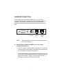
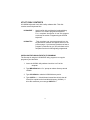
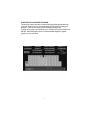
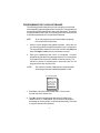
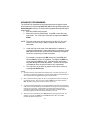
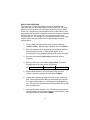
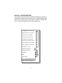
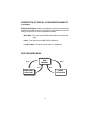
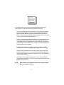
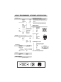
Model: LK5000
Programmable POS Keyboard
58 Keys with Built-in Scanner and MSR
USER MANUAL
NOTICE
The manufacturer of the POS programmable keyboard makes no
representations or warranties, either expressed or implied, by or with respect
to anything in this manual, and shall not be liable for any implied warranties
of fitness for a particular purpose or for any indirect, special or consequential
damages. Information in this document is subject to change without notice
and does not represent a commitment on the part of the manufacturer.
FCC NOTICE
This device complies with Part 15 of FCC Rules. Operations is subject to
the following two conditions: (1) this device may not cause harmful
interference. and (2) this device must accept any interference received,
including interference that may cause undesired operation.
LOGIC CONTROLS, INC.
355 Denton Ave
New Hyde Park, NY 11040
TEL: (516) 248-0400
FAX: (516) 248-0443
Email: [email protected]
http://www.logiccontrols.com
i
TABLE OF CONTENTS
FEATURES ............................................................................... 1
CARTON CONTENTS .............................................................. 2
HARDWARE CONNECTIONS ................................................. 3
FUNCTIONAL TEST ................................................................ 4
UTILITY DISK CONTENTS ...................................................... 6
INSTALLING THE LK5000.EXE UTILITY PROGRAM .............. 7
STARTING THE LK5000.EXE PROGRAM ............................... 7
PROGRAMMING THE LK5000 KEYBOARD ............................. 8
ADVANCED PROGRAMMING ................................................. 10
SPECIAL FEATURES OF THE LK5000 .................................... 11
INTER-STRING DELAY ............................................ 11
MULTI-LEVEL DEFINITION ...................................... 12
SPECIAL CONFIGURATIONS .................................................14
DATA TRANSFER MENU .........................................................16
SPECIFICATIONS....................................................................18
ADDENUM ................................................................................ 19
ii
FEATURES
•
Optional left or right laser bar code reader
•
Optional credit card reader
•
Contemporary design
•
Fully programmable
•
POS Layout
•
Tactile mechanical key switches
•
Keylock for multiple program layers
•
Multiple shift layers
•
True keyboard wedge function, operates with or without
computer keyboard
•
Up to 256 characters/key, include all function & control keys
•
No programming accessory kit, TSR program, or battery required
•
Available with RS232C output
1
CARTON CONTENTS
LK5000
1.
2.
Keyboard, Model LK5000
Computer interface cable - RJ11 6-pin Male
3.
101 keyboard interface cable PS/2 Male to AT Female
4.
5.
Utility software disk
Legend label sheet
6.
User’s manual
2
HARDWARE CONNECTIONS
The LK5000 can be connected to an IBM101 PC, XT, AT or clone
computer, PS/2 computer, or computer terminal. The following diagram
shows how the keyboard connects to the computer and standard
keyboard or other keyboard peripheral (magnetic stripe reader, scanner,
etc.).
To
Peripheral
NOTE:
To
Computer
Reserved
for optional
MSR
Before making any connections it is always advisable to
turn off the computer.
A. Connecting the LK5000 to an IBM101 PC, XT, AT, or clone
computer’s keyboard port:
1. Use the computer interface cable. Plug the AT or PS/2 Male
connector plug into the compter. Connect the RJ11 connector into
the “To Computer” connector on the LK5000.
2. Connect the keyboard interface cable to the standard keyboard. The
PS/2 Female connector plugs into the PS/2 connector on the rear
panel of the LK5000. The RJ11 connector plugs into the “To
Peripheral” connector on the back of the LK5000.
3
FUNCTIONAL TEST
For testing purposes, your LK5000 keyboard was pre-programmed with a
template called LK5000.TPL. The following simple steps will verify that
the keyboard is in good working condition:
1. Follow the Hardware Connections procedure described earlier in
this manual to connect the LK5000 to your computer.
2. Turn on your computer.
3. At the DOS prompt, press the upper left key of the keyboard.
4. The keyboard is working correctly when the words “LOGIC
CONTROLS PROGRAMMABLE KEYBOARD, MODEL LK5000"
appears on the monitor. To verify if the other keys are working
simply press each key and verify that the information displayed on
the monitor matches the template shown at the end of this section.
4
5
UTILITY DISK CONTENTS
All LK5000 keyboards come with a utility software disk. This disk
contains several important files:
LK5000.EXE -
Use this utility with or without the keyboard being
attached. It is used to program the keyboard.
For a complete description of how this program
works see the section “Programming the LK5000
keyboard”.
LK5000.TPL -
This template was pre-programmed into the
keyboard and matches the legend shown on the
previous page. If you have any questions on how to
program a particular key you can refer back to this
template to see how it was originally programmed.
INSTALLING THE LK5000.EXE UTILITY PROGRAM
The first step in using the LK5000.EXE utility program is to copy the
program to your hard drive.
1. Insert the LK5000 utility software into drive A or B of the
computer.
2. Type MD LK5000 at the “C>“ prompt to make a directory named
LK5000.
3. Type CD LK5000 to make the LK5000 directory active.
4. Type COPY A:*.* If the disk was inserted into drive A then all
files will be copied into the hard drive’s directory (LK5000). If
drive B is used then you must type COPY B:*.*
6
STARTING THE LK5000.EXE PROGRAM
This program can be used with or without the keyboard being attached to the
computer. Note that the PC must be booted up in DOS before starting the
program. It will not run properly under Windows DOS prompt.
To start the program, type LK5000 at the LK5000 DOS prompt and press
ENTER. When the program is up, it will automaticallly display the graphic
graphics screen as below.
7
PROGRAMMING THE LK5000 KEYBOARD
The following procedure will show you how to program your LK5000
with standard (keyboard) alphanumeric characters. The keyboard can
be programmed with either ASCII or Scan code information. The default
mode is the ASCII code mode. The following procedure assumes both
a LK5000 keyboard and a 101 keyboard are attached.
NOTE:
To run this program you must exit windows completely.
Do not shell out from Windows.
1. With the correct programming graphics present. Select the cell
you want to program by using the arrow keys on the 101 keyboard.
The Up and Down arrows will select the row while the Shift and
either the Right or Left arrow key will select the column.
2. Enter your programming text via the 101 keyboard. Continue
programming until all the keys are programmed. It is not necessary
to program all the keys for the LK5000 to function properly. The
maximum number of alphanumeric characters that can be
programmed for any one key is 256.
NOTE:
The maximum number of alphanumeric characters that
can be programmed per standard keyboard is 1856.
DATA TRANSFER MENU
Dos shell
File list (*.tpl)
Load file from disk
Read from keyboard
Save file to disk
Write to keyboard
Press ESC to Quit
3. Press F2 to call up the Data Transfer Menu. There will be
several choices to choose from.
4.
Type W to write the programmed data into the LK5000’s non
volatile memory. A “Writing Data” screen will open showing the
percentage of memory written. It will take approximately 7 seconds
to copy the data into the keyboard.
8
5. Type S to save the programmed data into the LK5000 directory.
You can select up to an 8 character name. It will be saved with a
.TPL extension.
6. Press ESC to terminate the Data Transfer Menu.
7. Press F10 followed by Y to exit the utility program.
8. To verify that your program has been successfully installed,
simply press any programmed key. The information stored in
that key will appear on the monitor.
9. The next time you want to install the legend you just created
simple press F2 to call up the Data Transfer Menu and then
press L to open the Load window.
10. Enter the name of the file in the legend window with its proper
extension (.TPL) and press ENTER. The legend will now show
on your monitor.
9
ADVANCED PROGRAMMING
The LK5000 POS keyboard can be programmed with all special control
and function keys such as the Shift, Ctrl, Alt, F1 through F12, and the up/
down/left/right arrow keys. The procedure to program these special keys is
shown below:
1. Start the LK5000 utility program.
2. Select the cell to be programmed. Press F8 to enter the scancode mode. The “code type” information changes from ASCII to
SCAN.
NOTE: The scan-code mode will only be active for this cell. You must
select F8 for each cell you want to program with scan-code
information.
3.
4.
Under the scan-code mode, each alphanumeric character is
enclosed in parenthesis. For special function or control keys, press
ESC (three vertical bars will be present) followed by the special
function or control key you want to program.
For example, to program the INS (insert) key, press ESC and
then the INS key on the 101 keyboard. To program the ESC key,
simply press the ESC key twice. Special function and control
keys will not appear inside parenthesis. The three vertical bars
will disappear once the special function key is depressed.
You may return to the start-up graphic screen (short menu) by
pressing Ctrl-Alt-F4 again.
NOTES:
1) Special function keys require ESC as the leading code. In the scan-code mode, you
can view the symbol of the special key or the hex code equivalent of the special key. To
view, simply press F7 to toggle between symbol and hex modes.
2)
Once a special function key (shift, ctrl, alt, etc.) is programmed it may be necessary to
un-select the function. To do so, press in sequence ESC, f (lower case F), 0 (zero),
ESC, followed by the special function key (shift, ctrl alt, etc.)
3)
Any given programmable location may be toggled between scan-code mode and ASCIIcode mode. Pressing the F8 key on the keyboard will change the cell’s programming
mode to scan-code mode. Pressing F9 on the keyboard will change the cell’s
programming mode to ASCII-code mode. Changing modes in a cell that has been
previously programmed will erase all the information in that cell.
4)
To enter hex scan-codes directly, press ESC followed by the 2-digit hex number. For
example, to program the CTRL key press ESC followed by 1D. The LK5000
program will add the leading zero
10
SPECIAL FEATURES OF THE LK5000
Besides being able to program all the keys of an IBM101 keyboard, the
LK5000 has also incorporated three state-of-the-art features which will
add flexibility and functionality to the keyboard.
INTER-STRING DELAY
This feature allows for a time delay(s) to be installed after a character(s)
has been inserted into a cell. To use this feature follow the steps below:
1. Enter the character(s) which will precede the delay. For
example, ABC.
2. Depress and hold the ALT key while pressing the letter D. A time
delay screen will open asking for the amount of delay you require
(up to 240 seconds). Select the appropriate delay and press
ENTER. A square pixel will appear on the programming line
immediately following the last character typed.
3. Type the next character(s), DEF. You can use more than one
delay per cell and each delay time can be different.
4. Save the template and then write the template to the keyboard.
5. Exit the LK5000 program by pressing F10 followed
by the letter Y.
6. Press the location key where the time delay character has been
stored. The monitor will display ABC immediately. After the delay
time you entered for this key has expired, DEF will be displayed on
the monitor and the cursor will be present at the prompt.
11
MULTI-LEVEL DEFINITION
This feature can increase the apparent number of programmable
keys by allowing you to program different levels into any cell. For every
different level you program you must select another key to be a “SHIFT
LEVEL” key. Programming is accomplished in the normal manner. After
programming the base level a separator bar must be entered to separate
the base level from the second level. You can program more than
two levels per cell. For example, if you needed to program small coffee,
medium coffee, and large coffee into one cell follow the procedure
outlined below:
1.
Select a blank cell and enter the most common coffee first
(medium coffee). Mark the legend sheet for this cell COFFEE.
2.
Enter the separator bar by depressing and holding the ALT key
and pressing the letter S. A solid line will appear on the
programming line immediately following the last character typed.
3.
Enter the second level (small coffee) followed by another
separator.
4.
Enter the third level of information (large coffee). The entire
programming line should look like the following:
F5 MEDIUM COFFEE
SMALL COFFEE
LARGE COFFEE
5.
Select a blank location to (F11) become the first level shift
position. Mark the legend sheet for this location SMALL.
6.
Change the programming mode of this cell to scan-code mode
(F8). Depress and hold the ALT key while pressing the letter A.
A triangle inside brackets (< >) will appear on the programming
line. This key when depressed and held will activate all keys that
have a second level.
7.
Select another blank location (F12). This will become the second
level shift position (will activate the third level of information). Mark
the legend sheet for this position LARGE.
12
8.
Change the programming mode of this cell to the scan-code mode
(F8). Depress and hold the ALT key while depressing the letter A
twice. Two triangles inside brackets will appear on the programming
line.
9. To use this feature in your application is extremely simple. When
medium coffee is desired just press the F5 key (the first level of
information stored in cell F5 will be sent to the computer). When
a small coffee is desired press and hold the F11 key while pressing
the F5 key (the second level of information stored in cell F5 will
be sent to the computer). When a large coffee is desired press
and hold the F12 key while pressing the F5 key (the third level of
information stored in cell F5 will be sent to the computer)
NOTE: There is no preset limit to the number of levels that can be
programmed into a keyboard.
13
SPECIAL CONFIGURATIONS
The keyboard can be set up with many different programming options. To
activate the configuration menu screen press F3. By depressing the highlighted letter in each option, the program will enable or disable that
option. The default settings are shown in the graphic below.
Send Break-codes for scan-codes
Yes
Enable beep while a key pressed
Yes
No beep if a key is undefined
Yes
Translate to code-set #2 for AT
Yes
Emulating XT keyboard always
No
Use ALT+num to generate ASCII
No
Enable Typematic for scan codes
No
Enable Typematic for ASCII codes
No
Emulating Link Terminal
No
InterCharacter Delay (+/-):
2 mS
Enable RS232 Output
No
Baud Rate:
9600
Parity:
NONE
Length of Data:
8 -bits
Press a High-light Letter to select
Esc ==> Quit from this menu
14
DESCRIPTION OF SPECIAL CONFIGURATION MENU F3
Send Break-code for scan-codes - Enables or disables the transmission
of break codes for each scan code programmed into the keyboard.
Enable beep while a key pressed - Enables or disables the entire keyboard
from beeping when any key is depressed.
No beep if a key is undefined - If a key is not programmed it will not
beep when depressed.
Translate to code set #2 for AT - Enables or disables the output of the
keyboard to be translated into AT scan code.
Emulating XT keyboard always - Enables or disables the output of the
keyboard to be translated into XT scan code.
Use ALT +num to generate ASCII - Enables or disables the ability to use
the ALT key along with the numeric keyboard to generate ASCII codes.
Enable typematic for scan codes - Enables or disables keys programmed
with scan code information to repeat the programmed characters as long
as the key remains depressed.
Enable typematic for ASCII codes - Enables or disables keys programmed
with ASCII code information to repeat the programmed characters as long
as the key remains depressed.
Emulating Link Terminal - Enables or disables the keyboards ability to
emulate a link terminal.
Intercharacter Delay (+/-) - The time delay between characters can be
adjusted from 1 millisecond to 266 milliseconds. This delay is set for all
characters programmed into the keyboard. Do not confuse this feature with
the inter-string delay feature.
15
DESCRIPTION OF SPECIAL CONFIGURATION MENU F3
(CONTINUED)
Enable RS232 Output - Enables or disables the output of the keyboard to
the RS232 port (DB9 connector). If this option is set to YES then the protocol
settings must be set to mirror the application software.
Baud Rate - This option selects 2400, 4800, 9600 and 19,200 baud
rates.
Parity - This option selects ODD, EVEN or NO parity.
Length of data - This option selects either 7 or 8 data bits.
DATA TRANSFER MENU
Save
COMPUTER'S
RAM
MEMORY
Load
Write
Read
LK5000
KEYBOARD
COMPUTER'S
HARD DISK
16
Dos shell
File list (*.tpl)
Load file from disk
Read from keyboard
Save file to disk
Write to keyboard
Press ESC to Quit
The LK5000 keyboard, working in conjunction with the LK5000.EXE
utility software, can perform the following powerful functions:
*
Save programmed data as a template file (.TPL) in both the keyboard
and the hard drive of the computer. To save programmed data to the
keyboard use the W (Write to keyboard) option of the Data Transfer
Menu. To save programmed data to the hard drive use the S (Save file
to disk) option of the Data Transfer Menu.
*
Load (L) a previously programmed template from the hard disk into the
computer’s volatile RAM memory. The same template can then be
written (W) into the non-volatile memory of the keyboard. This process,
as an example, allows a restaurant to change from a breakfast menu to
a lunch menu within 7 seconds.
*
Enables the computer to read (R) a template stored in the LK5000.
That template can then be saved (S) to the hard disk for future use.
*
Display a list of templates that have been stored onto the hard disk
within the LK5000 directory. From the Data Transfer Menu select F for
File List. The computer’s monitor will display the list of .TPL files stored
in the LK5000 directory.
*
Interruption of the programming process to shell out to DOS (D) to
perform other operations. To return to the programming process type
EXIT at the DOS prompt.
NOTE:
Never shell out of windows to work in this utility program.
Boot up computer in DOS.
17
LK5000 PROGRAMMABLE KEYBOARD SPECIFICATIONS
MECHANICAL
Weight
Basic Unit
with MSR
with Scanner
Dimension (in inches)
2.4lbs.
2.5lbs.
2.6lbs.
STD
w/Scanner
15.7
15.9
7.5
7.5
0.5
0.5
1.8
2.2
2.2
2.6
Full travel mechanical
Life cycle >10 million tactile cycles
2 tracks standard
Life Cycle
300,000 passes
Laser
Class
CDRH Class II
MTBF
100,000 hours
Width
Depth
Front Height
Max Height
w/legs ext.
Keys
MSR
SCANNER
ELECTRICAL
Input voltage (from computer)
Current
Basic Unit
MSR
Scanner
Standby
Scan Mode
Surge
+5VDC
25ma
50ma
PROGRAMMING THE KEYBOARD
1.Use the utility software supplied to program up to
256 alphanumeric characters per key. Utility
program will write to and read from computer disk
memor y.
2. Keyboard supports computer control keys (Shift,
CTRL, ALT, F1 through F12) and all arrow keys).
CONNECTOR PINOUTS
J1 (PS/2F) to PS/2 Keyboard
1
Keyboard Data
2
No Connection
3
Ground
4
+5VDC
5
Clock
6
Shield
J2 (RJ11F) to Computer
1
Clock
2
Data
3
No Connection
4
Ground
5
+5VDC
6
No Connection
15ua
100ma
130ma
6
5
3
4
2
1
123456
J3 (DB9M) RS232C to Computer
1
DCD
2
Receive Data (from computer)
3
Transmit Data (to computer)
4
DTR
ENVIRONMENTAL
1 2 3 4
5
Ground
Operating Temp
0 oC to +50 oC
o
o
6
DSR
Storage Temp
-20 C to +60 C
7
RTS
Relative Humidity
6 7 8 9
8
CTS
Operating
85% max. non-condensing
9
No connection
Non-operating
90% max. non-condensing
Pins 1,4, and 6 are tied together internally
Vibration (10 to 55 Hz.)
4G's
Pins 7 and 8 are tied together internally
Shock
40G's
INTERFACE
Keyboard Wedge
RS232C
Standard
Optional
GENERAL INFORMATION
Keyboard interface cable, utility software, and
legend labels supplied.
J3
J1
18
J2
ADDENDUM
SCANNER POSITION
The LK5000, a matrix programmable keyboard with built-in scanner,
was designed with the end user in mind. The scanner can be
factory installed on either side of the keyboard, giving the enduser the versatility required in todays applications.
PITCH ANGLE
To accomodate different customer installations the scanner’s
pitch angle can be adjusted via a lever on the bottom side of
the keyboard.
TO ACTIVATE THE SCANNER
The upper key of rightmost column on the LK5000 has been
hardwired to the scanner, and serves as the scanner’s trigger.
This key is dedicated to activating the scanner. The scanner
could also be set in an “always on” state by changing the default
settings on the scanner.
SYMBOLOGIES
The default parameters of the scanner includes the reading of
many different symbologies