1
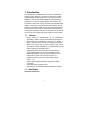
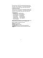
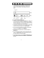
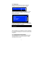
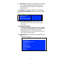
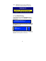
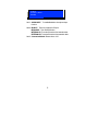
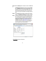
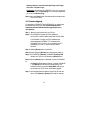
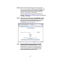
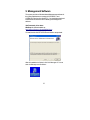
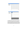
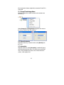
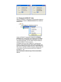
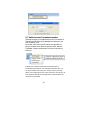
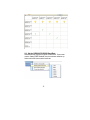
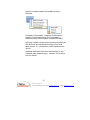
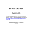
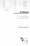
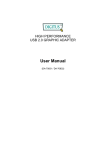
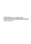
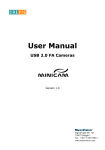
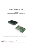
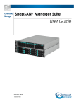
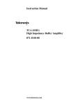
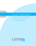
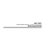
CCE900-IP-TR
CCE900-IP-T & CCE900-IP-R
User’s Guide
i-Tech Company LLC
TOLL FREE: (888) 483-2418 • EMAIL: [email protected] • WEB: www.iTechLCD.com
1. Introduction
The CCE900-IP-T & CCE900-IP-R is a solution of Audio/Video
extension over IP Ethernet. It is useful in a wide range of digital
signage applications that require one-to-many, many-to-many
distribution, such as: informational displays, corporate signage,
boardrooms, courtrooms, medical, military, and education. The
Transmitter connects with a PC or any device with VGA/DVI/Audio
outputs. The Receiver connects with a DVI/VGA display, and RS232 device. All available 100M, Giga or Fiber Ethernet LAN switch
can be used to inter-connect the Transmitters and the Receivers.
Just plug the transmitters and receivers into Ethernet network then
you can enjoy the real time high quality audio and video contents.
1.1
•
•
•
•
•
•
•
•
•
•
Features
Simply attach the VGA/DVI/audio to the CCE900-IP-T
transmitter, it starts to encode and streaming to the Ethernet.
Simply attach the CCE900-IP-R receiver to the display, it
starts to decode from the network to the display and speaker.
Support one-to-many with no delay in between each receiver.
Also support multiple Transmitters to multiple Receivers if the
Ethernet switch has the IGMP function.
Support both panel button and keyboard hotkey with On
Screen Display (OSD) menu to select transmitter source.
Support PS2/USB for remote PC keyboard/mouse control.
Support IR for remote control set-top box, DVD, TV.
Support RS-232 for remote turn on/off display, volume
control,… etc.
Support windows-based software to manage the TX/RX
connections.
Support HD video and stereo audio.
Plug-and-play, no additional software installation is required.
1.2
Specification
Input video & resolution
1
Input video can be VGA or DVI-D in all standard resolutions from
640 x 480 to 1920 x 1200 @ 60Hz ~ 70Hz and the following special
resolutions 1440 x 900, 1400 x 1050, 1680 x 1050, 1360 x 768.
Output video & resolution
Output video can be VGA or DVI-F in all standard resolutions from
640 x 480 to 1920 x 1080 @ 60Hz ~ 70Hz and the following special
resolutions 1440 x 900, 1400 x 1050, 1680 x 1050, 1360 x 768.
Output frame rate
– 640X480 @ 70fps 800X600 @ 70fps
– 1024X768 @ 60fps 1280X1024 @ 30fps
– 1600X1200 @ 30fps 720X480 @ 60fps
– 720X576 @ 50fps
1280X720 @ 30fps
– 1440x900 @ 30fps
1400 x1050 @ 30fps
– 1680x1050 @ 30fps 1360x768 @ 30fps
– 1920X1080 @ 25fps
Scalar support: Allows difference input and output resolution, also
support input-VGA/output DVI-D, input DVI-D/output VGA
LAN: 10/100Mbps, Auto-MDIX, Flow control.
IR Bridge: IR in/out, 38 KHz.
Remote PC Control: PS2 or USB
Audio/Microphone: 48 KHz stereo audio and microphone.
RS232 Bridge: CCE900-IP-R support remote RS232, baud 2400 ~
115200.
2
2. Installation Setup
2.1 Install CCE900-IP-T Transmitter
1. The DVI input of the CCE900-IP-T is [DVI-I] (VGA + DVI-D). You
can
use the accessory of VGA-to-DVI cable to connect CCE900-IPT to
the PC VGA-Out. Or you can prepare a DVI-to-DVI cable to
connect CCE900-IP-T to the PC DVI-Out.
2. There is a [VGA-Out] on the CCE900-IP-T for the VGA loop-out.
It is only available when the input video is DVI-A (or VGA). You
can attach a VGA monitor on this [VGA-Out] for local display.
3. Use accessory of audio cable to connect CCE900-IP-T [LineIN] to the PC Line-Out.
4. Use optional accessory of Mini USB-to-A cable to connect
CCE900-IP-T [Mini USB] to PC USB.
5. Use optional accessory of IR blaster cable to connect CCE900IP-T [IR Out] and adjust the IR blaster LED face to the IR
receiver of your Media Center PC, TV tuner card or DVD player.
6. Use CAT5e/6/7 cable to connect CCE900-IP-T [Ethernet] to
the Ethernet switch (or directly to the CCE900-IP-R). All of
CCE900-IP-T and CCE900-IP-R must be put in the same
network and should not be inter-connected with router.
7. Use the included 12V DC power adapter to connect CCE900IP-T [DC IN] power socket and plug the power supply to
wall.
8. There is a [Status] LED and 2 RJ45 LEDs on the CCE900-IP-T,
please refer to the below table for the status of CCE900-IP-T:
[Status] LED
Red
Green
RJ45 LED
Green
Status
Orange
System OK, network is not
connected
On
Blink
On
On
System failed
System OK, network is connected
On
3
On
9.
On
On
System OK, network overload
The [Reset] button on the CCE900-IP-T Rear panel can be
used for entering “Advance Setup Mode”, please refer to
Chapter 4. The CCE900-IP-T panel diagram is shown as
below:
2.2 Install CCE900-IP-R Receiver
1. The DVI output of the CCE900-IP-R is [DVI-I] (VGA + DVI-D). You
can use the accessory of VGA-to-DVI cable to connect CCE900IP-R to the VGA monitor. Or you can prepare a DVI-to-DVI cable
to connect CCE900-IP-R to the DVI monitor.
2. Use accessory of audio cable to connect CCE900-IP-R [Line Out]
to speaker and plug microphone into the [Mic In] port.
3. If you need remote keyboard/mouse function, plug keyboard
and mouse to the [PS2] or optional [USB] port.
4. If you need remote RS232 function, plug RS232 cable to the
[RS232] port.
5. If you need remote IR function, connects optional IR receiver
cable to the [IR extender] port and positioned the receiver to
be visible from the front of the Display.
6. Use CAT5e/6/7 cable to connect CCE900-IP-R [Ethernet] to the
Ethernet switch (or directly to the CCE900-IP-T). All of CCE900IP-T and
4
CCE900-IP-R must be put in the same network and should not
be inter-connected with router.
7. Connect the included DC 5V 2A power adapter to the DC-IN and
plug the power supply to wall. To avoid damage to the CCE900IP-R, please use power adapter in the package.
8. There is a [Source] button on the front panel for the system
OSD operation menu. Please refer to Chapter 3 for detail.
9. There is a [Power] LED and 2 RJ45 LEDs on the CCE900-IP-R,
please refer to the below table for the status of CCE900-IP-R:
[Power] LED [R
J45]
Red Green Green Orange
Off
On
Blink
On
On
On
On
On
On
On
On
On
On
On
Status
No Power
System OK, network is not connected
System failed
System OK, network is connected, but not able to
link with Transmitter
System OK, linked with Transmitter
System OK, dis-connected with Transmitter (the
[Power] LED in orange color)
System OK, network overload
10. The [Reset] button on the CCE900-IP-R Rear panel can be used
for entering “Advance Setup Mode”, please refer to Chapter 4.
The CCE900-IP-R panel diagram is shown as below:
5
3. System Menu (OSD)
There are 2 types of OSD (On Screen Display) menu in CCE900-IP-R
Receiver: Transmitter List menu and System menu. You can enter
the Transmitter List menu by pressing <Ctrl><Ctrl> hotkey. By
pressing the CCE900-IP-R [Source] button you can enter the
System menu.
3.1 Transmitter List menu
To active the Transmitter List OSD menu, press the <Ctrl> key
twice within two seconds, you may see the OSD menu showing a
list of all CCE900-IP-T Transmitters as below picture:
The above menu shows 4 x CCE900-IP-T are found in the network
with name of KV-9001-PC1, KV-9001-PC2, …KV-9001-PC4. The 2, 0,
1, 3 in the right column indicates the number of Receivers are
currently connected with that Transmitter. Navigate to the desired
Transmitter (PC) with the arrow keys, and press <Enter>. The
selected CCE900-IP-T (PC) screen appears on the display, and uses
the console keyboard and mouse to control the selected PC. Press
[F1] to refresh Transmitters list which are activated. Press [F10] to
change hotkey option: <CTRL>, <SHIFT>, or <ALT>.
6
3.2 System menu
When the CCE900-IP-R Receiver is turned on, it will search
CCE900-IP-T transmitters on the network as below:
Searching CCE900-IP-T
…
When the CCE900-IP-R found one or more CCE900-IP-T on the
network, it will show all the CCE900-IP-T Transmitters on the
System menu as below:
>CCE900-IP-T-0337 (192.168.168.201, 03:27)
>CCE900-IP-T-0428 (192.168.168.202, 04:28)
>VGA SYNC
>REFRESH
>CCE900-IP-T SETTING
>CCE900-IP-R OFF
>Connection Method
>EXIT
Press the [Source] button of the CCE900-IP-R allows the proper
CCE900-IP-T to be selected, after 3 seconds the CCE900-IP-R will
connect to that CCE900-IP-T as below:
Connecting to…
After the CCE900-IP-T and CCE900-IP-R connection is established,
the CCE900-IP-R will display the PC screen that is connected to that
CCE900-IP-T.
3.3 The Other System menu Functions
When the [source] button of CCE900-IP-R is pushed, the system
menu OSD will pop out. You can push the button to navigate
other System menu functions.
7
3.3.1 VGA SYNC: This function is only available when the CCE900IP-T is connected with VGA input, and sometimes the
picture shifts from screen, this function is used to auto
adjust the picture.
3.3.2 REFRESH: To refresh the CCE900-IP-T Transmitters list.
3.3.3 CCE900-IP-T SETTING: Use this function to setup CCE900IP-T:
>MULTI/ONE CCE900-IP-R
>BANDWDITH SETTING
>INFORMATION
>EXIT
3.3.3.1MULTI/ONE CCE900-IP-R: To set CCE900-IP-T as
multicast mode (for one-to-many) or unicast mode (for
one-to-one).
3.3.3.2BANDWIDTH SETTING
This function adjusts the bandwidth usage of the CCE900IP-T. There are three levels for selection: LOW, MID, HIGH.
Please note to set LOW, it will use lower network
bandwidth and get a more efficient performance but will
come with lower image quality.
3.3.3.3INFORMATION: This function shows the CCE900-IP-T and
AV901R basic information:
CCE900-IP-T
VERSION aa26
SUPPORT MULTI CCE900-IP-R
BANDWIDTH LOW
DVI IN 1024 X 768
CCE900-IP-R
VERSION a901 0126
IP 192.168.168.22
VGA OUT 1024 X 768
MIC IN
INTERNAL IR
8
3.3.4
CCE900-IP-R OFF: To disable the connection between the
CCE900-IP-R and connected CCE900-IP-T. To enable the
connection, press the push button again.
CCE900-IP-R off
3.3.5
Connection Method: The system provides 3 connection
method:
>First Available
>By Priority
>Dedicated
>EXIT
3.3.5.1 First Available: This function sets the CCE900-IP-R to
connect to the first available CCE900-IP-T which it found
first.
3.3.5.2 By Priority: This function sets the CCE900-IP-R to
connect to the CCE900-IP-T according to the priority. You
can set the 1st priority and the 2nd priority for 2 different
CCE900-IP-T transmitters. As the following picture,
there are two sections, each has a list of all Transmitters
that are currently on the network; just press the source
button to move the highlight to the desired Transmitter,
wait a few seconds, and the settings will be saved and
restart. The prefixed “*” indicate the Transmitter with
that priority setting.
9
3.3.5.3
Dedicated: This function sets the CCE900-IP-R to
connect with a dedicated CCE900-IP-T Transmitter.
3.4 The CCE900-IP-R Setting
From the System menu, you can push the [source] button of
CCE900-IP-R and navigate to the “>REFRESH”, the display will
show as below:
Searching CCE900-IP-T …
Please push the button again during the system is still searching
the CCE900-IP-T. The OSD menu with “CCE900-IP-R SETTING”
will be shown as below:
>CCE900-IP-T-0337 (192.168.168.201, 03:27)
>REFRESH
>CCE900-IP-R SETTING
>CCE900-IP-R OFF
Push the [source] button again to navigate to the “>CCE900-IP-R
SETTING”, the following OSD menu will prompt:
10
>
>
>
>
AUDIO INPUT
IR INPUT
Connection Method
RETURN
3.4.1 AUDIO INPUT: To enable/disable the microphone input
function.
3.4.2 IR INPUT: There are 3 options for IR input:
IR DISABLE: Turn off the IR function.
INTERNAL IR: To set the IR receiver from internal socket.
EXTERNAL IR: To set the IR receiver from extension cable.
3.4.3 Connection Method: Please refer to 3.3.5.
11
4. Advanced Setup
This section is in detail for how to assign IP address for CCE900IP-T and CCE900-IP-R, and how to upgrade firmware.
4.1 Setup IP address
A HTTP server is embedded in CCE900-IP-T and CCE900-IP-R for
changing IP and firmware upgrade. However, the changing IP and
firmware upgrade is available in Setup Mode only, not in Normal
Mode.
For the CCE900-IP-R, there are 2 internal IP: the operation IP
and configuration IP. The operation IP is changeable but the
configuration IP is always fixed at 192.168.168.22.
For the CCE900-IP-T, the operation IP is same as configuration IP.
The factory default IP is shown on the label under the box. That
means, you should remember the final IP, otherwise, you will not
be able to configure the CCE900-IP-T. In case of missing the final
IP, you should use a special software tool to find IP out.
Please follow below steps to configure the IP settings:
Step 1: For CCE900-IP-R, assign your PC IP address in between
192.168.168.1 and 192.168.168.254, excluding
192.168.168.22, and the subnet mask with 255.255.255.0.
For CCE900-IP-T, the factory default IP is shown on the
label that stuck on the bottom of the CCE900-IP-T. The PC
IP address need to be on the same network as CCE900-IPT. For example, if the CCE900-IP-T IP is 10.100.1.10, you
might set your PC IP address as 10.100.1.1 and the subnet
mask as 255.0.0.0.
Step 2: Unplug the power plug, hold the [Reset] button of the
device.
Step 3: Keep holding the [Reset] button and plug the power on.
Step 4: Release the [Reset] button when you see the [Status] (or
[Power]) LED starts blinking red.
12
Step 5: After the [Reset] button is released, in case of CCE900-IPR,
the [Power] LED will become orange; in case of CCE900IP-T, the [Status] LED will become orange blinking. This
indicates the device is entered Setup Mode and you can
start to setup and get access to the HTTP server of the
device. If you are not in this status, any setup process is in
vain.
Step 6: Use a straight Ethernet Cable to connect the PC with the
device. (The [Status] or [Power] LED is still lit in orange.)
Step 7: Ping the connected device through the sequence, Start,
Run, cmd, ping [TX IP] or ping 192.168.168.22 (for RX). If
you receive the reply, it means the device is ready for
setup mode. Use IE browser to open the setup page. For
CCE900-IP-R, the URL is http://192.168.168.22. For
CCE900-IP-T, the URL is http://[TX IP]. In this page, you
can setup IP address, subnet mask, gateway, device
name, network protocol and destination.
Device Name: the name of the device.
13
Network protocol: To be on the safe side, always use IP Layer,
and don’t use MAC Layer.
Destination: this setting is for CCE900-IP-T only. For one-to-one
application, you can use Unicasting. For one-to-many application,
you must use Multicasting.
Step 8: After click [Save] button, the settings will be saved and the
device will restart.
4.2 Firmware Upgrade
To upgrade the CCE900-IP-T and CCE900-IP-R, you should save
the new firmware into your PC first. Please disable antivirus
software and firewall until the firmware upgrade process is
accomplished.
Step 1: Save the new firmware into your PC first.
Step 2: For CCE900-IP-R, assign your PC IP address to
192.168.168.11 and the subnet mask with 255.255.255.0.
For CCE900-IP-T, assign your PC IP address to the
same network as CCE900-IP-T. For example, if the
CCE900-IP-T IP is 10.100.1.10, you might set your PC
IP address as 10.100.1.1 and the subnet mask as
255.0.0.0.
Step 3: Hold the [Reset] button of the device.
Step 4: Keep holding the [Reset] button and plug the power on.
Step 5: The CCE900-IP-T [Status] or CCE900-IP-R [Power] LED
will blink red. Then you can release the [Reset] button.
Step 6: After the [Reset] button is released, in case of CCE900-IPR,
the [Power] LED will become orange; in case of CCE900-IPT, the [Status] LED will become orange blinking. This
indicates the device is entered Setup Mode and you can
get access to the HTTP server for firmware upgrade.
Step 7: Use a straight Ethernet Cable to connect the PC with the
device. (The [Status] or [Power] LED is still lit in orange.)
14
Step 8: Ping the connected device through the sequence, Start >
Run > cmd > ping 192.168.168.22 or ping [CCE900-IP-T IP].
You will receive the reply if the connection is established.
Disable the antivirus and firewall software and use IE
browser to get access the web server.
Type http://[IP]/upg.htm to upgrade the CCE900-IP-T
firmware. Type http://192.168.168.22/upg.htm to upgrade the
CCE900-IP-R firmware.
Step 9: Navigate to the firmware file and click [Upgrade]. Upgrade
process may take a few minutes. Please do not turn off PC
or the device or unplug the Ethernet cable. It will cause
damage of the device. After firmware upgrade is
accomplished, turn off the device.
Note: You have to disable antivirus software and firewall
software before you upgrade firmware. Firmware
upgrade process cannot be interrupted so please do
not turn off your computer or the upgraded device
or disconnect the Ethernet cable until the process is
finished. Otherwise the system will crush.
15
5. Management Software
The system provides a Windows-based Management software for
the system administrator to manage all CCE900-IP-T and
CCE900-IP-R devices from his/her PC. You should download and
install the below software before installing this Management
software.
.Net Framework 2.0 or above
WinPcap 4.1.2, Downloadable at:
http://www.winpcap.org/install/default.htm
To install, double click SETUP.EXE and follow the setup wizard:
After the installation is finished, click “LAN Manager 4.0” icon to
start the Management Software:
16
The Management screen is split into two frames: on the left is a
Tree view of the Transmitters (TX) and the connected Receivers
(RX); on the right is a two-tab view, one is a List view of the RX,
and the other is a Matrix view of TX and RX; the former lists all of
RX but no TX, and the latter displays a matrix table in a coordinate
style: the horizontal axis is a list of RX and the vertical axis is of TX.
17
If the intersected cell shows a light bulb, it means the RX and TX is
connected.
5.1 Change IP and change Name
Right-click the device you desire to change, and a context menu
will show up:
Select [Change IP] or [Change Name] and type the IP or name on
the pop-up window, and click [Submit]:
5.2 Reboot the device
Right-click the device you desire to reboot, select [Reboot] from
the menu.
5.3 Information
Right-click the device, select [Information], a window will pop up
with information about the device. The value in the version field
may or may not display the version; when it fails to detect the
version, it will display “N/A”.
18
5.4 Display the CCE900-IP-T video
When the CCE900-IP-T transmitter is connecting with at least one
CCE900-IP-R, it will have a [Display Screen] function enabled as
below picture.
Select a CCE900-IP-T transmitter and right-click the [Display
Screen] function, a window will pop up displaying that CCE900IP-T screen source. Depending on the performance of your PC
and network bandwidth, you can activate multiple windows for
multiple CCE900-IP-T screen sources.
The default frame rate for the CCE900-IP-T is 30 frames per
second. You can change the frame rate by clicking [Setting] > [Tx
Frame Rate Setting] on the upper left corner of the Management
Main screen. Click it and a window will pop up, and from here you
can specify the FPS (Frames per second) for the CCE900-IP-T
transmitter (1 ~ 30).
Note: This function is effective only on TX of version b204 or
above).
19
5.5 Switch from one Transmitter to another
There are two ways you can switch RX from one TX to another TX.
There are two-Tab views on the Management main screen: List
view and Matrix view.
In List view, select one or more RX items, then right-click it to
bring up a context menu. Move the mouse over the “Switch to
Transmitter” function, and select the TX from the sub-menu by
clicking it.
In Matrix view, click the intersected cell that represents a
Transmitter with a Receiver. The selected cell is ticked "S". You
can select multiple cells one by one. Finally, click the [connect]
button on the upper right corner to start connection. The tick sign S
in the checked cells will turn into light bulb in a few seconds if the
connection is succeeded.
20
5.6 Set the CCE900-IP-R RS232 Baud Rate
Select Receiver(s), right-click to get the context menu. Then mouseover the “Setting UART Baudrate” item, the sub-menu will show up.
Select one from the list to set the baud rate.
21
5.7 Send Messages to the CCE900-IP-R RS-232 port
Select Receiver(s), right-click to get the context menu. Then
mouse-over the “Send UART Messages” item, and click it to bring
up a window.
First, specify the message format: ASCII or Binary. If you specify
Binary, the message is supposed to be like “00 01 … ff”; be sure to
separate each byte with white space.
Second, type the message in the “Request” text area.
Third, click “Submit” to send the message. If there is response, it
will be displayed in the “Response” text area.
22
You could also type the message and save it as a template, so that
you could load it from the template without having to re-type it
again.
Click “Save as Template”, and a window will pop-up; type the
name of the template and click “Submit”.
To load a template you previously saved, just click “Load from
Template” to bring up a window that lists the templates you saved
previously. Select the template and click “Select”. Or if you want
to delete the template, just click “Delete”
5.8 Manage Connection Method
This function is for RX with version ab26 or above; if the RX is as
far back as under ab26 or if the version information is “N/A”, the
“Connection Method” item will be disabled. There are three
23
options for connection method: First Available, By Priority,
Dedicated.
The default is “First Available”, it means the RX will connect to
whichever TX that first discovered. Click “First Available”, a
window will pop up; just click “Submit” to complete the setting.
“By Priority” means the RX will connect according to the priority list.
Click “By Priority” and a similar window will pop up; you could
specify up to two TX. Just place them in order of priority and click
“Submit”.
“Dedicated” means the RX will connect to the specified TX. Click
“Dedicated” and a window will pop up. Select one TX from the list
and click “Submit”.
24
i-Tech Company LLC
TOLL FREE: (888) 483-2418 • EMAIL: [email protected] • WEB: www.iTechLCD.com