1
PlugIn
IPEmotion PlugIn
IPETRONIK CAN
User manual
May 2012
All rights reserved!
Content
Content
Content .........................................................................................2
1 Important information ............................................................4
1.1
Liability, Warranty, Copyright, License agreement.................................................... 4
1.1.1 Limitation of liability ................................................................................................ 4
1.1.2 Warranty................................................................................................................. 4
1.1.3 Copyright and Duplication...................................................................................... 4
1.1.4 Software license agreement .................................................................................. 4
2 General information ...............................................................6
2.1
2.2
2.2.1
2.2.2
2.2.3
2.3
2.4
2.5
2.5.1
2.5.2
2.5.3
2.5.4
2.6
About this manual ...................................................................................................... 6
Version....................................................................................................................... 6
User manual IPEmotion PlugIn IPETRONIK CAN................................................. 6
IPEmotion PlugIn IPETRONIK CAN ...................................................................... 6
IPEmotion............................................................................................................... 6
Legend of the used icons .......................................................................................... 6
Support ...................................................................................................................... 7
Related documentations............................................................................................ 7
IPEmotion............................................................................................................... 7
Manual MAL development ..................................................................................... 7
Engine compartment measurement....................................................................... 7
Vehicle measurement ............................................................................................ 7
Documentation feedback........................................................................................... 8
3 Introduction ............................................................................9
4 Setting up and removing .....................................................12
4.1
System requirements............................................................................................... 12
4.1.1 Hardware.............................................................................................................. 12
4.1.2 Platforms .............................................................................................................. 12
4.2
Installing IPEmotion PlugIn IPETRONIK CAN ........................................................ 13
4.3
Uninstalling IPEmotion PlugIn IPETRONIK CAN .................................................... 14
5 Working with IPEmotion PlugIn IPETRONIK CAN.............16
5.1
5.2
5.3
5.4
5.4.1
Defining general settings ......................................................................................... 16
The export function .................................................................................................. 17
Defining components ............................................................................................... 18
Defining channels .................................................................................................... 19
Devices of the component group “Voltage/current” ............................................. 19
IPEmotion PlugIn IPETRONIK CAN
IPETRONIK GmbH & Co. KG
2/ 27
Content
5.4.2
5.4.3
5.4.4
5.4.5
5.4.6
Devices of the component group “Temperature” ................................................. 22
Devices of the component group “Pressure” ....................................................... 23
Devices of the component group “Counter/frequency” ........................................ 25
Devices of the component group “Communication”............................................. 26
Devices of the component group “Multi devices”................................................. 27
IPEmotion PlugIn IPETRONIK CAN
IPETRONIK GmbH & Co. KG
3/ 27
Important information
1 Important information
Please follow these instructions before and during the use and application of any
IPETRONIK product!
1.1 Liability, Warranty, Copyright, License agreement
1.1.1 Limitation of liability
Any liability of IPETRONIK, its representatives, agents and the like, especially with regard to
personal injury or damage to property of any kind, shall be excluded (within the legally
admissible framework), as far as, the instructions and warnings, as mentioned below, have
not been followed.
1.1.2 Warranty
Products, accessories and services have a 12 months warranty.
All product data, specifications, drawings, etc., correspond to the current condition of the
indicated creation date. For the purpose of optimizing technical processes and production,
some details of our modules and accessory components may be modified at any time
without prior notification.
Although the present document has been prepared with the utmost attention to detail, it may
not be exempt of misprints, typing or transcription errors. These errors are not covered by
any warranty.
1.1.3 Copyright and Duplication
We reserve all rights, in particular those of property, copyright and trademarks. The rights
related to any third party trademarks mentioned in the present document remain unaffected.
This document may not be duplicated, partially or entirely without the prior approval from
IPETRONIK GmbH & Co. KG. All graphics and explanations are copyright protected. Any
use beyond the scope of the document is prohibited.
1.1.4 Software license agreement
IMPORTANT: THIS IS A LEGAL AGREEMENT BETWEEN YOU, LICENSEE, AND
IPETRONIK GMBH & CO. KG/IPETRONIK INC. ("IPETRONIK"). BY CHECKING “I ACCEPT
ALL OF THE TERMS CONTAINED IN THE ABOVE AGREEMENT” DURING
INSTALLATION, COPYING OR USING THIS PRODUCT IN ANY WAY YOU
ACKNOWLEDGE THAT YOU HAVE READ THIS LICENSE AND THAT YOU
UNDERSTAND AND EXPRESSLY AGREE TO BE BOUND BY THE TERMS AND
CONDITIONS SET FORTH BELOW.
This software is property of IPETRONIK GmbH & Co. KG, and is protected by copyright
laws. Its total or partial reproduction is strictly forbidden.
IPEmotion PlugIn IPETRONIK CAN
IPETRONIK GmbH & Co. KG
4/ 27
Important information
The following actions are allowed:
Installing and using a copy of the product on a single computer or network. This
copy may only be used by a single user at a time. If the product is to be used by
multiple users, an additional license will be required for each user.
Creating a copy of the product for filing or backup purposes.
Using a copy of the product on a home computer or on a portable computer,
provided that the copy is not installed at the same time also on your main
computer.
Transferring the product to another person is only permitted, if the license rights
are also transferred, and if the product and any copies created are completely
deleted or erased (including copies on hard drives), and if the new owner agrees
with the requirements of this license.
IPEmotion PlugIn IPETRONIK CAN
IPETRONIK GmbH & Co. KG
5/ 27
General information
2 General information
2.1 About this manual
The manual IPEmotion PlugIn IPETRONIK CAN describes the structure of the PlugIn and
how to use the features for configuring devices, which are based on the IPETRONIK CAN
driver, in IPEmotion, taking acquisitions and managing and analyzing the resulting data.
Please read the manual IPEmotion PlugIn IPETRONIK CAN carefully to get to know the
operating and to learn more about the functions and special features. This manual also
contains information for installing and removing the software.
2.2 Version
2.2.1 User manual IPEmotion PlugIn IPETRONIK CAN
This manual has the version number 01.06.
2.2.2 IPEmotion PlugIn IPETRONIK CAN
The descriptions in this documentation refer to the current release with the version number
01.06.
2.2.3 IPEmotion
The descriptions in this documentation refer to the current release with the version number
01.09.
The PlugIn requires at least IPEmotion V01.00 on your computer.
2.3 Legend of the used icons
Tip
This icon indicates a useful tip that facilitates the application
of the software.
Information
This icon indicates additional information for a better
understanding.
IPEmotion PlugIn IPETRONIK CAN
IPETRONIK GmbH & Co. KG
6/ 27
General information
Attention!
This icon indicates important information to avoid potential
error messages.
2.4 Support
Headquarter:
IPETRONIK GmbH & Co. KG
Im Rollfeld 28
76532 Baden-Baden, Germany
Phone +49 72 21 99 22 0
Fax +49 72 21 99 22 100
[email protected]
www.ipetronik.com
Limited commercial partnership with its head office in Baden-Baden, registry court HRA No.
201313
IPETRONIK Verwaltungs GmbH Baden-Baden is an individually liable society,
registry court Mannheim HRB No. 202089
Management: Erich Rudolf, Andreas Wocke
Technical support and product information
www.ipetronik.com
e-mail: [email protected]
2.5 Related documentations
2.5.1 IPEmotion
The documentation IPEmotion.pdf provides you with a description and useful information
related to IPEmotion. This documentation is stored in the following standard language
dependent directory: C:\Programs\IPETRONIK\IPEmotion Vxx.xx.xx\Help.
2.5.2 Manual MAL development
The documentation MAL development.pdf provides you with a description and useful
information related to the use of the interface with plug-in components and IPEmotion.
2.5.3 Engine compartment measurement
The documentation Engine_Compart_Measurement.pdf provides you with a description and
useful information related to the IPETRONIK M devices.
2.5.4 Vehicle measurement
The documentation Vehicle_Measurement.pdf provides you with a description and useful
information related to the IPETRONIK SIM devices.
IPEmotion PlugIn IPETRONIK CAN
IPETRONIK GmbH & Co. KG
7/ 27
General information
Please note that this documentation is currently only available in German.
2.6 Documentation feedback
At IPETRONIK, the technical publications team strives to produce documentations of the
highest quality and values your feedback as a reader and user. If you have any comments or
suggestions regarding our product manuals, contact us under [email protected].
Please inform us about the following points:
Version number (Select Options → Add Ins from the menu to display the version
number.),
Name of the guide,
Page number or section title,
Brief description of the content (e.g. inaccurate instructions, grammatical errors, or
information that require clarification),
Any suggestions for a general documentation improvement.
IPEmotion PlugIn IPETRONIK CAN
IPETRONIK GmbH & Co. KG
8/ 27
Introduction
3 Introduction
The IPETRONIK CAN PlugIn offers you the ability to use M and SIM devices of IPETRONIK
within IPEmotion.
The devices of the IPETRONIK CAN system are separated into groups according their
functionality. The current version supports the following four component groups:
Voltage/current
Temperature
Pressure
Counter/frequency
Communication
Multi devices
Each single group contains different devices, which can be used for acquiring data. Each
device is an independent acquisition system and can be used as a stand-alone devices, as
well as, in combination with other devices in a CAN bus network. The current IPEmotion
PlugIn IPETRONIK CAN version offers the following devices (they are listed accordingly to
the above classification):
Voltage/current:
M-SENS
M-SENS DSP
M-SENS 8
M-SENS 8 DSP
M-SENS 8plus
M-SENS 8plus DSP
SIM-SENS
SIM-SENS DSP
SIM-VIN
SIM-VOUT
SIM-STG
SIM-DMS
IPEmotion PlugIn IPETRONIK CAN
IPETRONIK GmbH & Co. KG
9/ 27
Introduction
SIM-DMS DSP
Temperature:
Mc-THERMO
M-THERMO
M-THERMO2
M-THERMO2 u
M-THERMO 16
M-THERMO T
M-THERMO T16
M-RTD2
µ-THERMO
SIM-TH II-8
SIM-TH II-16
SIM-THERMO
SIM-TH II-8N
SIM-PT100
SIM-PT200
Pressure:
CANpressure ABS 1, 2, 5, 10, 20, 25, 30, 50, 100, 200, 250 Bar
CANpressure REL 1, 2, 5, 10, 20, 25, 30, 50, 100, 200, 250 Bar
Counter/frequency:
M-FRQ
SIM-CNT
Communication:
SIM-ECU 552, 553, 554
SIM-SER
IPEmotion PlugIn IPETRONIK CAN
IPETRONIK GmbH & Co. KG
10/ 27
Introduction
SIM-ECU552[120], SIM-ECU553[120], SIM-ECU554[ECU]
SIM-SER[16]
Multi devices
MultiDAQ
Each single device provides channels.
Please find detailed information about the M and SIM devices of IPETRONIK
in the manuals Engine_Compart_Measurement and Vehicle_Measurement.
IPEmotion PlugIn IPETRONIK CAN
IPETRONIK GmbH & Co. KG
11/ 27
Setting up and removing
4 Setting up and removing
4.1 System requirements
The minimum hardware and platform requirements for the application of the IPEmotion
PlugIn IPETRONIK CAN are outlined below.
4.1.1 Hardware
The minimum hardware requirements correspond to those of IPEmotion.
4.1.2 Platforms
The IPEmotion PlugIn IPETRONIK CAN can be run under the following operating systems:
Windows XP (32 Bit),
Windows Vista (32 Bit).
IPEmotion PlugIn IPETRONIK CAN
IPETRONIK GmbH & Co. KG
12/ 27
Setting up and removing
4.2 Installing IPEmotion PlugIn IPETRONIK CAN
The following chapter guides you through the installation process of the IPETRONIK CAN
PlugIn.
IPEmotion PlugIn IPETRONIK CAN needs administrator rights during the
installation. For working with the PlugIn you need at least limited user’s or
default user’s rights (Vista).
The installation of IPEmotion PlugIn IPETRONIK CAN is based on an installation wizard that
guides you through the setup process step by step. You can start the installation wizard from
the USB flash drive or, if you have downloaded the setup program from the IPEmotion forum
at www.ipemotion.com, from the setup file itself.
To install IPEmotion PlugIn IPETRONIK CAN:
1. Start the installation wizard from the USB flash drive or from the setup file.
USB flash drive: Connect the USB flash drive to the USB port of your computer and
follow the instructions of the installation wizard.
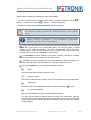
Setup file: Browse the location of the setup file and double-click IPEmotion PlugIn
IPETRONIK CAN.exe to start the installation wizard.
Depending on the used PC operating system, a security warning appears.
Click Run to start the installation wizard.
2. Setup language/Setup-Sprache/Langue d’installation: Select the language for the
installation process. You can choose between the languages German (Germany), English
(USA), and French (France).
Click OK to start the IPETRONIK CAN installation wizard.
3. Welcome screen: This is the first screen in the IPEmotion PlugIn IPETRONIK CAN
installation wizard.
Click Next to continue.
4. Destination folder:
IPEmotion PlugIn IPETRONIK CAN
IPETRONIK GmbH & Co. KG
13/ 27
Setting up and removing
Due to the security model of Microsoft Corporation related to .NET applications,
the installation of IPEmotion PlugIn IPETRONIK CAN on a local drive is
recommended.
According to the Microsoft conformance guidelines for Windows applications
the files are installed to the default locations that are specific to the operating
system and language.
Accept the default installation location for IPEmotion PlugIn IPETRONIK CAN. To select
another location click Change.
After you have specified the location for the installation, click OK to return to the Destination
folder screen.
Click Next to continue.
5. Ready to install the program: This screen indicates that IPEmotion PlugIn IPETRONIK
CAN is ready to install.
Click Install to start the installation.
6. Installing: A progress bar is shown during the installation process.
7. InstallShiel Wizard Completed: After the successful installation, the following screen is
shown.
Click Finish to exit the installation wizard.
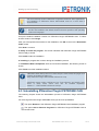
A Windows-Silent-Setup cannot run other setups in silent mode, the plugin must
therefore be installed as silent, too:
Setup IPEmotion PlugIn IPETRONIK CAN.exe /S /v/qn
CAN-PlugIn setup copies CAN-Server into Temp directory and installs CANServer in Silent mode, which must also be installed separately:
msiexec /i ".../IPETRONIK CAN-Server.msi"/qn
4.3 Uninstalling IPEmotion PlugIn IPETRONIK CAN
The following chapter shows the deinstallation process of IPEmotion PlugIn IPETRONIK
CAN.
For removing IPEmotion PlugIn IPETRONIK CAN you have two possibilities:
The option Remove of the IPEmotion PlugIn IPETRONIK CAN installation program
The option Add or Remove Programs for IPEmotion PlugIn IPETRONIK CAN in
the Control Panel.
IPEmotion PlugIn IPETRONIK CAN
IPETRONIK GmbH & Co. KG
14/ 27
Setting up and removing
With both methods you can remove files, folders and registry entries from your computer,
which has been created during the installation.
Removing IPEmotion PlugIn IPETRONIK CAN with the installation program
To do so, proceed as follows:
1. Click in the menu Start on your computer on Settings and then Control Panel.
2. Double-click in the Control Panel on Add or Remove Programs.
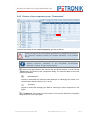
3. Select from the program list the entry IPEmotion PlugIn IPETRONIK CAN and click
Change to start the installation wizard.
Click Next to advance to the Program maintenance screen.
4. Program maintenance: This screen allows you to modify, repair or remove IPEmotion
PlugIn IPETRONIK CAN. Select Remove and click Next to continue.
5. Remove the program: This screen indicates that your installation is now ready to
remove. Click Remove to start the removing process.
6. Uninstalling: A progress bar is shown during the uninstalling process.
7. InstallShiel Wizard Completed: This screen is shown after the successful deinstallation.
Click Finish to exit the installation wizard.
After removal, IPEmotion PlugIn IPETRONIK CAN is no longer indicated in the program list.
Removing IPEmotion PlugIn IPETRONIK CAN with the deinstallation function of the
Control Panel
To do so, proceed as follows:
1. Click in the menu Start on your computer on Settings and then Control Panel.
2. Double-click in the Control Panel on Add or Remove Programs.
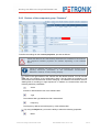
3. Select from the program list the entry IPEmotion PlugIn IPETRONIK CAN and click
Remove to start the installation wizard.
4. Click Yes to start the deinstallation.
5. A progress bar is shown during the uninstalling process.
After the successful removal of IPEmotion PlugIn IPETRONIK CAN, the program has been
removed from your computer and is no longer indicated in the program list.
IPEmotion PlugIn IPETRONIK CAN
IPETRONIK GmbH & Co. KG
15/ 27
Working with IPEmotion PlugIn IPETRONIK CAN
5 Working with IPEmotion PlugIn
IPETRONIK CAN
The following chapter offers an overview of the available commands and their functions. In
addition, it is shown how to use the IPETRONIK CAN devices and the software IPEmotion
for configuring and acquiring data, as well as, managing and analyzing the acquired data.
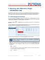
5.1 Defining general settings
The main navigation tab Signals contains all available and connected systems with the
respective type description and channels. Click on the button Add system or Add component
to expand the configuration by further systems or components.
IPEmotion Options
detecting.
-> PlugIns offers you the ability to define up to 4 interfaces for
Open the Options tab and activate the desired interfaces and the corresponding medium
and CAN bus within the Hardware detection interfaces section.
To define the general settings for the system properties, proceed as follows:
Please find detailed information about the functionality and meaning of the
following IPEmotion parameters in the IPETRONIK documentation
IPEmotion: General.
Select in the left tree view the desired system. You can find the CAN hardware tab
in the window of the configuration dialog. You can set the following configuration
definitions:
Medium
The medium defines the interface to the acquisition system. The CAN medium already
found by the driver is shown automatically.
CAN bus
IPEmotion PlugIn IPETRONIK CAN
IPETRONIK GmbH & Co. KG
16/ 27
Working with IPEmotion PlugIn IPETRONIK CAN
The IPEmotion parameter CAN bus defines the CAN channel, where the devices are
connected to and which is used by the devices for communicating.
Baud rate
The baud rate defines the transfer rate, which is valid for all system devices, for
communicating to the devices.
Device baud rate
Baud rate initialization
Activate or deactivate the use of the baud rate at the interface initialization.
The Options tab offers the following configuration possibilities:
Synchronized mode
Activate or deactivate the use of the synchronized Free Running mode. The PlugIn
defines a device as clock generator (Master), which sets the acquisition clock for all
connected devices (Slave). All devices of an acquisition system have a synchronized
internal clock.
Automatic CAN ID placing
Activate or deactivate the automatic assigning of the CAN parameters.
Start CAN-ID
Define the start CAN-ID for the automatic CAN-ID assignation.
Names out of serial numbers
Create the names of the devices and channels out of the serial numbers.
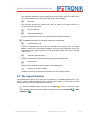
5.2 The export function
The CANdb export allows you to save the configuration in a CANdb description file. If you
want to create a CANdb description file from the complete system, you get a file in the ZIP
format, which includes all CANdb files of the devices.
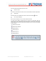
Select the desired system and click on the Export
button or open the context
menu with the right mouse button. Select the signal export into a CANdb file
CANdb file
or XML
.
IPEmotion PlugIn IPETRONIK CAN
IPETRONIK GmbH & Co. KG
17/ 27
Working with IPEmotion PlugIn IPETRONIK CAN
The dialog window Save file as will be initialized. Select the desired location and
confirm with Save.
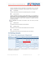
5.3 Defining components
To define the general settings for the device properties, proceed as follows:
Please find detailed information about the functionality and meaning of the
following IPEmotion parameters in the IPETRONIK documentation
IPEmotion: General.
Select in the left tree view the desired device. You can find the Extended tab in the
window of the configuration dialog. You have the ability to select the following properties:
Front number
The front number defines the last digits of the device number. It refers to the last five
digits of the serial number by default. The serial number is mandatory for detecting,
using, and distinguishing the device from others within IPEmotion. The serial number
is composed of the front number and the device type and can generally be found at
the back of the device or is detected automatically in IPEmotion.
Clock
The clock defines the acquisition clock by using an internal clock generator or another
system device. You can synchronize the data acquisition of the devices.
Channel balance
IPEmotion PlugIn IPETRONIK CAN
IPETRONIK GmbH & Co. KG
18/ 27
Working with IPEmotion PlugIn IPETRONIK CAN
Activate or deactivate the offset compensation of the acquisition chain, i.e. the initial
excitation compensation at switching-on. Set the acquisition value to a defined value.
29-bit identifier
Activate or deactivate the extension of the address range from 11 bit to 29 bit.
Ignore the device
Activate or deactivate this function to ignore single devices. It is not necessary to
delete the device from the configuration because it is not addressed at initializing. This
function allows you to ignore not available devices of a complex configuration without
defining the configuration as invalid. Further calculations or analyses include the
corresponding NoValue.
The Information tab provides the information, which was read by the device
hardware.
Calibration date
The calibration date shows the date of the last calibration.
Hardware version
The hardware version shows the current hardware version of the devices.
Firmware version
The firmware version shows the current firmware version of the devices.
5.4 Defining channels
5.4.1 Devices of the component group “Voltage/current”
Selecting one or several channels is optically signalized and the corresponding LED is
flashing at the connected device.
IPEmotion PlugIn IPETRONIK CAN
IPETRONIK GmbH & Co. KG
19/ 27
Working with IPEmotion PlugIn IPETRONIK CAN
Please note the following requirement to use this functionality:
- The Allow accesses while configuring option must be activated! (IPEmotion options
PlugIns -> Plugin specific options
-> Options -> Hardware accesses)
->
To define the settings for the channel properties, proceed as follows:
Please note that not all in the following listed tabs are available for each device.
The respective available properties are defined depending on the selected
device.
Please find detailed information about the functionality and meaning of the
following IPEmotion parameters in the IPETRONIK documentation
IPEmotion: General, Format, Scaling, Display.
Select in the right window of the channel view the desired channel. You can find the
Offset tab in the window of the configuration dialog. You have the ability to define
settings to the offset compensation. An offset compensation defines the value
compensation to a defined value for balancing an excitation offset. This defined value
has to be within the maximum admissible physical range.
The Excitation tab offers settings of the sensor excitation. The sensor excitation
defines the excitation for the respective connected channel.
The Filter tab offers the possibility to set the hardware filter and the averaging. The
hardware filter defines the anti-aliasing filter for avoiding too high frequencies.
By using the Adjust tab you can define the following settings:
Mode
The mode defines the adjusting mode to be used.
Reference value
The reference value defines the value, which is recorded after an offset compensation.
Offset value
The offset value is only updated if the device is read with the Detect
function.
Run channel calibration
Start a channel calibration of one or several selected channels.
You have also the ability to calibrate with the context menu functionality. Mark the
desired system or the corresponding device and open the context menu with the right
mouse button. Select Extras and the desired calibration mode. There are the following
modes available:
IPEmotion PlugIn IPETRONIK CAN
IPETRONIK GmbH & Co. KG
20/ 27
Working with IPEmotion PlugIn IPETRONIK CAN
Calibrate all channels
Calibrate group Manual
Calibrate group 1
Calibrate group 2
Calibrate group 3
Calibrate group 4
Please note the following requirement to use this functionality:
- The Allow accesses while configuring option must be activated!
(IPEmotion options
-> PlugIns -> Plugin specific options
-> Options
-> Hardware accesses)
The Mode tab offers settings of the inversion. The inversion defines the acquisition
range inversion of the input signal.
By using the CAN timeout tab you have the ability to select the following properties:
CAN timeout
The CAN timeout defines the seconds to send an alternate value if no message is
received on the CAN bus.
Output value
The output value defines the alternate value to be send after a CAN timeout.
By using the STG mode tab you can define the following settings:
Bridge
You can define the following settings for the bridge: Type, Resistance, Connection.
Define the bridge type, the bridge resistance, and the conductor count, which are
connected to the bridge at the entry.
Shuntcheck
You can define the following settings for the Shuntcheck: Resistance, Quadrant.
Define the resistance value for checking the respective quadrant of the bridge and the
bridge quadrant to be checked.
IPEmotion PlugIn IPETRONIK CAN
IPETRONIK GmbH & Co. KG
21/ 27
Working with IPEmotion PlugIn IPETRONIK CAN
5.4.2 Devices of the component group “Temperature”
To define the settings for the channel properties, proceed as follows:
Please note that not all in the following listed tabs are available for each device.
The respective available properties are defined depending on the selected
device.
Please find detailed information about the functionality and meaning of the
following IPEmotion parameters in the IPETRONIK documentation
IPEmotion: General, Format, Scaling, Display.
Select in the right window of the channel view the desired channel. You can find the
Thermo tab in the window of the configuration dialog. You have the ability to select the
following properties:
Break detection
Activate or deactivate the conductor break detection for identifying error status. At a
sensor break a defined value of –60 °C is set.
Averaging
Activate or deactivate averaging the data for reducing the noise components in the
signal.
The Mode tab offers settings of the inversion. The inversion defines the acquisition
range inversion of the input signal.
IPEmotion PlugIn IPETRONIK CAN
IPETRONIK GmbH & Co. KG
22/ 27
Working with IPEmotion PlugIn IPETRONIK CAN
5.4.3 Devices of the component group “Pressure”
To define the settings for the channel properties, proceed as follows:
Please note that not all in the following listed tabs are available for each device.
The respective available properties are defined depending on the selected
device.
Please find detailed information about the functionality and meaning of the
following IPEmotion parameters in the IPETRONIK documentation
IPEmotion: General, Format, Scaling, Display.
Select in the right window of the channel view the desired channel. You can find the
Filter tab in the window of the configuration dialog. The tab offers the possibility to set
the hardware and software filter and the averaging. The hardware filter defines the antialiasing filter for avoiding too high frequencies. In addition, the software filter offers the
following definition possibilities:
Active
Activate or deactivate the use of the software filter.
Type
The software filter type defines the filter characteristic.
Frequency
The frequency defines the limit frequency of the software filter.
By using the Adjust tab you have the ability to select the following properties:
Mode
IPEmotion PlugIn IPETRONIK CAN
IPETRONIK GmbH & Co. KG
23/ 27
Working with IPEmotion PlugIn IPETRONIK CAN
The mode defines the adjusting mode to be used.
Reference value
The reference value defines the value, which is recorded after an offset compensation.
Offset value
The offset value is only updated if the device is read with the Detect
function.
Run channel calibration
Start a channel calibration of one or several selected channels.
You have also the ability to calibrate with the context menu functionality. Mark the
desired system or the corresponding device and open the context menu with the right
mouse button. Select Extras and the desired calibration mode. There are the following
modes available:
Calibrate all channels
Calibrate group Manual
Calibrate group 1
Calibrate group 2
Calibrate group 3
Calibrate group 4
Please note the following requirement to use this functionality:
- The Allow accesses while configuring option must be activated!
(IPEmotion options
-> PlugIns -> Plugin specific options
-> Options
-> Hardware accesses)
IPEmotion PlugIn IPETRONIK CAN
IPETRONIK GmbH & Co. KG
24/ 27
Working with IPEmotion PlugIn IPETRONIK CAN
5.4.4 Devices of the component group “Counter/frequency”
To define the settings for the channel properties, proceed as follows:
Please note that not all in the following listed tabs are available for each device.
The respective available properties are defined depending on the selected
device.
Please find detailed information about the functionality and meaning of the
following IPEmotion parameters in the IPETRONIK documentation
IPEmotion: General, Format, Scaling, Display.
Select in the right window of the channel view the desired channel. You can find the
Input signal tab in the window of the configuration dialog. You have the ability to select
the following properties:
Threshold on
Threshold on defines the value to detect the entry signal as active.
Threshold off
Threshold off defines the value to detect the entry signal as inactive.
Edge
The edge defines the direction for detecting the pulse.
DC compensation
Activate or deactivate the compensation of a direct voltage offset of the signal.
Gate time
Define the time for recording the frequency.
IPEmotion PlugIn IPETRONIK CAN
IPETRONIK GmbH & Co. KG
25/ 27
Working with IPEmotion PlugIn IPETRONIK CAN
Minimal value
The Excitation tab offers settings of the sensor excitation. The sensor excitation
defines the excitation for the respective connected channel.
By using the Filter tab you have the ability to set the hardware filter. The hardware
filter defines the anti-aliasing filter for avoiding too high frequencies.
The Mode tab offers settings of the inversion. The inversion defines the acquisition
range inversion of the input signal.
By using the Analog output tab you can define the following settings:
Min
Min defines the lower scaling limit of the analog excitation output.
Max
Max defines the upper scaling limit of the analog excitation output.
5.4.5 Devices of the component group “Communication”
To define the settings for the channel properties, proceed as follows:
Please note that not all in the following listed tabs are available for each device.
The respective available properties are defined depending on the selected
device.
Please find detailed information about the functionality and meaning of the
following IPEmotion parameters in the IPETRONIK documentation
IPEmotion: General, Format, Scaling, Display.
Select in the right window of the channel view the desired channel. You can find the
Mode tab in the window of the configuration dialog. You have the ability to select the
following properties:
Inverted
Activate/Deactivate the inversion of the acquisition range of the entry signal.
IPEmotion PlugIn IPETRONIK CAN
IPETRONIK GmbH & Co. KG
26/ 27
Working with IPEmotion PlugIn IPETRONIK CAN
5.4.6 Devices of the component group “Multi devices”
To define the settings for the channel properties, proceed as follows:
Please note that not all in the following listed tabs are available for each device.
The respective available properties are defined depending on the selected
device.
Please find detailed information about the functionality and meaning of the
following IPEmotion parameters in the IPETRONIK documentation
IPEmotion: General, Format, Scaling, Display.
Select in the right window of the channel view the desired channel. You can find the
Input signal tab in the window of the configuration dialog. You have the ability to select
the following properties:
Averaging
Activate/Deactivate averaging the values
Break detection
Activate/Deactivate the conductor break detection.
IPEmotion PlugIn IPETRONIK CAN
IPETRONIK GmbH & Co. KG
27/ 27