1
Warranty
General. Seller warrants that its products furnished hereunder will, at the time of delivery, be free from defects in material and workmanship and will
conform to Seller's applicable specifications or, if appropriate, to Buyer's specifications accepted in writing by Seller.
SELLER'S OBLIGATION OR LIABILITY TO BUYER FOR PRODUCTS WHICH DO NOT CONFORM TO THE ABOVE STATED WARRANTY
SHALL BE LIMITED TO SELLER, AT SELLER'S SOLE DISCRETION, EITHER REPAIRING, REPLACING, OR REFUNDING THE PURCHASE
PRICE OF THE DEFECTIVE PRODUCT(S) PROVIDED THAT WRITTEN NOTICE OF SAID DEFECT IS RECEIVED BY SELLER WITHIN THE
TIME PERIODS SET FORTH BELOW:
i. for all software products including licensed programs, thirty (30) days from date of initial delivery;
ii. for all hardware products including complete systems, one (1) year from date of initial delivery;
iii. for all special products, sixty (60) days from date of initial delivery; and further, all products warranted hereunder for which Seller has
received timely notice of nonconformance must be returned FOB Seller's plant within thirty (30) days after the expiration of the warranty
periods set forth above.
The foregoing warranties shall not apply to any products which Seller determines have, by Buyer or otherwise, been subjected to operating and/or
environmental conditions in excess of the maximum value established therefor in the applicable specifications, or any products that have been the
subject of mishandling, misuse, misapplication, neglect, improper testing, repair, alteration or damage.
Limitation. THE PROVISIONS OF THE FOREGOING WARRANTIES EXTEND TO BUYER ONLY AND NOT TO BUYER'S CUSTOMERS OR
USERS OF BUYER'S PRODUCTS AND ARE IN LIEU OF ANY OTHER WARRANTY, WHETHER EXPRESS, IMPLIED OR STATUTORY,
INCLUDING ANY IMPLIED WARRANTY OF MERCHANTABILITY OR FITNESS FOR A PARTICULAR PURPOSE. IN NO EVENT SHALL
SELLER BE LIABLE FOR INCIDENTAL, SPECIAL OR CONSEQUENTIAL DAMAGES.
Seller's liability arising out of the production, sale or supply of products or their use or disposition, whether based upon warranty, contract, tort or
otherwise, shall not exceed the actual purchase price paid by Buyer for Seller's products. Seller's liability for any claim of any kind shall in no case
exceed the obligation or liability specified in this Warranty.
Technical Assistance. Seller's Warranty as hereinabove set forth shall not be enlarged, diminished or affected by, and no obligation or liability shall
arise or grow out of, Seller's rendering of technical advice, facilities or service in connection with Buyer's order of the goods furnished hereunder.
Warranty Procedures. Buyer shall notify Seller of any products which it believes to be defective during the applicable warranty period and which
are covered by the warranty set forth above. Buyer shall not return any products for any reason without the prior authorization of Seller and issuance
of a Return Material Authorization number. After issuance of an RMA number, such products shall be promptly returned by Buyer (and in no event
later than thirty (30) days after the warranty expiration date), transportation and insurance prepaid, to the Seller's designated facility for examination
and testing. Seller shall either repair or replace any such products found to be so defective and promptly return such products to Buyer, transportation
and insurance prepaid. Should Seller's examination and testing not disclose any defect covered by the foregoing warranty, Seller shall so advise
Buyer and dispose of or return the products in accordance with Buyer's instructions and at Buyer's sole expense, and Buyer shall reimburse Seller
for testing expenses incurred at Seller's then current repair rates.
Repair Warranty. Seller warrants its repair work and/or replacement parts for a period of ninety (90) days from receipt by Buyer of the repaired or
replaced products or for the remainder of the warranty period for the initial delivery of such order as set forth above in paragraph a, whichever is
greater.
Critical Applications. Certain applications using Seller's products may involve potential risks of death, personal injury, or severe property or
environmental damage ("Critical Applications").
SELLER'S PRODUCTS ARE NOT DESIGNED, INTENDED, AUTHORIZED, OR WARRANTED TO BE SUITABLE FOR USE IN
LIFE-SUPPORT DEVICES OR SYSTEMS, SAFETY EQUIPMENT, NUCLEAR FACILITY APPLICATIONS OR OTHER CRITICAL APPLICATIONS
WHERE MALFUNCTION OF THE PRODUCT CAN BE EXPECTED TO RESULT IN PERSONAL INJURY, DEATH OR SEVERE PROPERTY
DAMAGE. BUYER USES OR SELLS SUCH PRODUCTS FOR USE IN SUCH CRITICAL APPLICATIONS AT BUYER'S OWN RISK AND AGREES
TO DEFEND, INDEMNIFY AND HOLD HARMLESS SELLER FROM ANY AND ALL DAMAGES, CLAIMS, SUITS OR EXPENSE RESULTING
FROM SUCH USE.
Static Sensitive. Seller ships all product in anit-static packages. Seller's Warranty as hereinabove set forth shall not cover warranty repair,
replacement, or refund on product or devices damaged by static due to Buyer's failure to properly ground.
Application Support. Dataforth provides timely, high-quality product support. Just call 1-800-444-7644 TOLL-FREE (USA)
Returns/Repair Policy. All warranty and repair requests should be directed to the Dataforth Customer Service Department at (520) 741-1404. If a
product return is required, request a Return Material Authorization (RMA) number. You should be ready to provide the following information:
1. Complete product model number.
2. Product serial number.
3. Name, address, and telephone number of person returning product.
4. Special repair instructions.
5. Purchase order number for out-of-warranty repairs.
The product should be carefully packaged, making sure the RMA number appears on the outside of the package, and ship prepaid to:
Dataforth Corporation
3331 E. Hemisphere Loop
Tucson, AZ 85706 USA
Phone: 520-741-1404
FAX: 520-741-0762
The information provided herein is believed to be reliable; however, DATAFORTH assumes no responsibility for inaccuracies or omissions.
DATAFORTH assumes no responsibility for the use of this information, and all use of such information shall be entirely at the user's own risk.
Application information is intended as suggestions for possible use of the products and not as explicit performance in a specific application. Prices
and specifications are subject to change without notice. No patent rights or licenses to any of the circuits described herein are implied or granted to
any third party. DATAFORTH does not authorize or warrant any DATAFORTH product for use in life support devices and/or systems.
MA1016
SLX100/101
Quick Start Guide
Table of Contents
isoLynxTM Analog I/O Base Unit
1.1 Unpacking
Each isoLynxTM Analog I/O Base Unit is shipped in electro-static discharge (ESD) protective
packaging. Use appropriate ESD protection measures while unpacking. Check visually for
physical damage. If physical damage is noted, file a claim with the shipping carrier.
1
isoLynx™ Analog I/O Base Unit
1.1
Unpacking .....................................................................1
1.2
Package Contents and Physical Description................1
1.3
Verifying Basic Operation .............................................1
isoLynxTM SLX100 Analog I/O Base Unit comprised of:
1.3.1
Hardware Configuration................................................1
1.3.2
Using PC Sample Software ..........................................2
1.3.3
Using isoLynx™ Commands Directly .............................4
- isoLynxTM Controller (containing one processor board, one I/O signal converter board, and
one optional industrial communication board) mounted on the 12 ch. Analog I/O Base Unit
backpanel.
2
isoLynx™ Digital I/O Backpanel
1.2 Package Contents and Physical Description
- One CD-ROM containing isoLynxTM data acquisition software drivers/examples and
documentation files including: Help files, manuals, and specifications.
- This isoLynxTM SLX100/101 Quick Start Guide.
2.1
Unpacking .....................................................................5
2.2
Package Contents and Physical Description................5
2.3
Verifying Basic Operation .............................................5
2.3.1
Hardware Configuration................................................5
2.3.2
Using PC Sample Software ..........................................6
2.3.3
Using isoLynx™ Commands Directly .............................9
This completes the unpacking and visual inspection of the isoLynxTM Analog I/O Base Unit.
For detailed configuration and installation in your system, reference the isoLynxTM Hardware
User Manual and/or the isoLynxTM Software User Manual on CD-ROM.
For rapid verification of basic functionality, continue with the next section.
1.3 Verifying Basic Operation
At this point you are ready to insert an SCM5B module, connect an input signal, and apply
power to the isoLynxTM Analog I/O Base Unit in order to verify its basic operation.
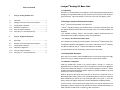
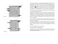
1.3.1 Hardware Configuration
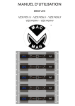
Install any SCM5B input module in any channel position 0 through 11. Connect an
appropriate sensor or calibration signal source to the field I/O connectors on the backpanel
in front of the module (refer to figure 1.1 for I/O connection diagram). The isoLynxTM Analog
I/O Base Unit will demonstrate basic operation without any modules installed as long as at
least one input channel is configured.
Install an SLX140-X cable (RJ45 both ends) and an SLX142-X or SLX143-X RJ-45 to
DB-9 adapter (either factory preset or user configurable) between the isoLynxTM Analog I/O
Base Unit RS-232 port (RJ-45) and a PC serial port (DB-9). See Figure 1.1. From the
factory, all units are shipped configured for RS-232, 9600 bits/second (Baud) interface.
Connect a +5VDC 1 Amp (minimum) power supply and turn on the power. Observe the +5V
LEDs lighting. Observe that RD and TD LEDs are off. Observe the A/D LED blinking at a
steady rate after an initial pause. For location of LEDs, see Figure 1.1.
1
Table of Contents
isoLynxTM Analog I/O Base Unit
1.1 Unpacking
Each isoLynxTM Analog I/O Base Unit is shipped in electro-static discharge (ESD) protective
packaging. Use appropriate ESD protection measures while unpacking. Check visually for
physical damage. If physical damage is noted, file a claim with the shipping carrier.
1
isoLynx™ Analog I/O Base Unit
1.1
Unpacking .....................................................................1
1.2
Package Contents and Physical Description................1
1.3
Verifying Basic Operation .............................................1
isoLynxTM SLX100 Analog I/O Base Unit comprised of:
1.3.1
Hardware Configuration................................................1
1.3.2
Using PC Sample Software ..........................................2
1.3.3
Using isoLynx™ Commands Directly .............................4
- isoLynxTM Controller (containing one processor board, one I/O signal converter board, and
one optional industrial communication board) mounted on the 12 ch. Analog I/O Base Unit
backpanel.
2
isoLynx™ Digital I/O Backpanel
1.2 Package Contents and Physical Description
- One CD-ROM containing isoLynxTM data acquisition software drivers/examples and
documentation files including: Help files, manuals, and specifications.
- This isoLynxTM SLX100/101 Quick Start Guide.
2.1
Unpacking .....................................................................5
2.2
Package Contents and Physical Description................5
2.3
Verifying Basic Operation .............................................5
2.3.1
Hardware Configuration................................................5
2.3.2
Using PC Sample Software ..........................................6
2.3.3
Using isoLynx™ Commands Directly .............................9
This completes the unpacking and visual inspection of the isoLynxTM Analog I/O Base Unit.
For detailed configuration and installation in your system, reference the isoLynxTM Hardware
User Manual and/or the isoLynxTM Software User Manual on CD-ROM.
For rapid verification of basic functionality, continue with the next section.
1.3 Verifying Basic Operation
At this point you are ready to insert an SCM5B module, connect an input signal, and apply
power to the isoLynxTM Analog I/O Base Unit in order to verify its basic operation.
1.3.1 Hardware Configuration
Install any SCM5B input module in any channel position 0 through 11. Connect an
appropriate sensor or calibration signal source to the field I/O connectors on the backpanel
in front of the module (refer to figure 1.1 for I/O connection diagram). The isoLynxTM Analog
I/O Base Unit will demonstrate basic operation without any modules installed as long as at
least one input channel is configured.
Install an SLX140-X cable (RJ45 both ends) and an SLX142-X or SLX143-X RJ-45 to
DB-9 adapter (either factory preset or user configurable) between the isoLynxTM Analog I/O
Base Unit RS-232 port (RJ-45) and a PC serial port (DB-9). See Figure 1.1. From the
factory, all units are shipped configured for RS-232, 9600 bits/second (Baud) interface.
Connect a +5VDC 1 Amp (minimum) power supply and turn on the power. Observe the +5V
LEDs lighting. Observe that RD and TD LEDs are off. Observe the A/D LED blinking at a
steady rate after an initial pause. For location of LEDs, see Figure 1.1.
1
isoLynxTM Analog I/O Base Unit
1.3.2 Using PC Sample Software
Create the C:\Program Files\Dataforth\isoLynx folder on your local hard drive. From the
installation CD-ROM, copy the Demo folder and all of its contents to the folder you just
created.
1.3.2.1 Minimum PC Requirements
Windows 98, ME, 2000, or XP and the minimum hardware to support the operating system.
1.3.2.2 Configuring an Input Channel
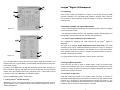
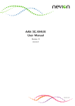
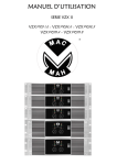
From the Demo folder run the isoLynxTM Configuration sample program Config.exe. Config
will display a dialog box similar to Figure 1.2. Figure 1.2 shows the Configuration Sample
dialog box as it appears after configuration, so some information and labels may have
changed from the initial states.
(1) The button at the top right corner is labeled Connect or Disconnect. For information
on the other options in this section, see the isoLynxTM Software User Manual. Clicking on
Connect displays an isoLynxTM Connect dialog box. Clicking on Connect within that box
triggers the Config program to make a serial connection to the isoLynxTM Analog I/O Base
Unit. For information on the other options in the isoLynxTM Connect dialog box, see the
isoLynxTM Software User Manual. After a short pause, the Connect dialog box disappears
and the Connect button in the Configuration dialog box shows Disconnect.
(2) At this time, observe the information boxes in the I/F Configuration section are
displaying the communication parameters, in particular, Baudrate: 9600 and Interface
Type: RS-232. For information on the other options in this section, see the isoLynxTM
Software User Manual.
(3) Observe the I/O Type boxes in the I/O configuration section have become activated.
Observe the box labeled I/O Panel shows the designation: Aio.0, meaning: Analog I/O
Panel 0. For information on the other options in this section, see the isoLynxTM Software
User Manual.
(4) Click on the down arrow button of the I/O Type box next to the channel you have
populated with a module. Select Ai from the pull down list. Note the Channel Present box
now has a check mark.
(5) Click on the Configure button in the bottom right corner to send isoLynxTM its new
configuration. Click Yes in the I/O Configure question box. After a short communication
pause, the isoLynxTM Analog I/O Base Unit is now configured.
(6) Before running the Input sample program, you must Disconnect the Configure sample
program. The example in Figure 1.2 has configured panel 0, channel 0. At this time, you
may also click on to minimize or X to close the Configuration dialog box.
2
Figure 1.1
1.3.2.3 Reading an Input Channel
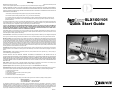
Next locate and run the Input sample program Input.exe. Input will display a dialog box
similar to Figure 1.3. Figure 1.3 shows the Input Sample dialog box as it appears after
execution, so some information and labels may have changed from the initial states.
(1) The button at the top right corner is labeled Connect or Disconnect. For information
on the other options in this section, see the isoLynxTM Software User Manual. Clicking on
Connect displays an isoLynxTM Connect dialog box. Clicking on Connect within that box
triggers the Input program to make a serial connection to the isoLynxTM Analog I/O Base
Unit. For information on the other options in the isoLynxTM Connect dialog box, see the
isoLynxTM Software User Manual. After a short pause, the Connect dialog box disappears
and the Connect button in the Input dialog box shows Disconnect.
(2) At this time observe in the Channel Data section that the channel you have configured
has a check mark. All others are blank.
(3) Note in the Channel Options section, the I/O Panel box contains the designation:
Aio.0. There are four selection boxes. All have check marks. The recommended
configuration is: leave Read Group checked, uncheck Stop On Error, leave Floating-Point
Data checked and uncheck Average Data. For the meanings and implications of the other
choices, see the isoLynxTM Software User Manual.
3
isoLynxTM Analog I/O Base Unit
1.3.2 Using PC Sample Software
Create the C:\Program Files\Dataforth\isoLynx folder on your local hard drive. From the
installation CD-ROM, copy the Demo folder and all of its contents to the folder you just
created.
1.3.2.1 Minimum PC Requirements
Windows 98, ME, 2000, or XP and the minimum hardware to support the operating system.
1.3.2.2 Configuring an Input Channel
From the Demo folder run the isoLynxTM Configuration sample program Config.exe. Config
will display a dialog box similar to Figure 1.2. Figure 1.2 shows the Configuration Sample
dialog box as it appears after configuration, so some information and labels may have
changed from the initial states.
(1) The button at the top right corner is labeled Connect or Disconnect. For information
on the other options in this section, see the isoLynxTM Software User Manual. Clicking on
Connect displays an isoLynxTM Connect dialog box. Clicking on Connect within that box
triggers the Config program to make a serial connection to the isoLynxTM Analog I/O Base
Unit. For information on the other options in the isoLynxTM Connect dialog box, see the
isoLynxTM Software User Manual. After a short pause, the Connect dialog box disappears
and the Connect button in the Configuration dialog box shows Disconnect.
(2) At this time, observe the information boxes in the I/F Configuration section are
displaying the communication parameters, in particular, Baudrate: 9600 and Interface
Type: RS-232. For information on the other options in this section, see the isoLynxTM
Software User Manual.
(3) Observe the I/O Type boxes in the I/O configuration section have become activated.
Observe the box labeled I/O Panel shows the designation: Aio.0, meaning: Analog I/O
Panel 0. For information on the other options in this section, see the isoLynxTM Software
User Manual.
(4) Click on the down arrow button of the I/O Type box next to the channel you have
populated with a module. Select Ai from the pull down list. Note the Channel Present box
now has a check mark.
(5) Click on the Configure button in the bottom right corner to send isoLynxTM its new
configuration. Click Yes in the I/O Configure question box. After a short communication
pause, the isoLynxTM Analog I/O Base Unit is now configured.
(6) Before running the Input sample program, you must Disconnect the Configure sample
program. The example in Figure 1.2 has configured panel 0, channel 0. At this time, you
may also click on to minimize or X to close the Configuration dialog box.
2
Figure 1.1
1.3.2.3 Reading an Input Channel
Next locate and run the Input sample program Input.exe. Input will display a dialog box
similar to Figure 1.3. Figure 1.3 shows the Input Sample dialog box as it appears after
execution, so some information and labels may have changed from the initial states.
(1) The button at the top right corner is labeled Connect or Disconnect. For information
on the other options in this section, see the isoLynxTM Software User Manual. Clicking on
Connect displays an isoLynxTM Connect dialog box. Clicking on Connect within that box
triggers the Input program to make a serial connection to the isoLynxTM Analog I/O Base
Unit. For information on the other options in the isoLynxTM Connect dialog box, see the
isoLynxTM Software User Manual. After a short pause, the Connect dialog box disappears
and the Connect button in the Input dialog box shows Disconnect.
(2) At this time observe in the Channel Data section that the channel you have configured
has a check mark. All others are blank.
(3) Note in the Channel Options section, the I/O Panel box contains the designation:
Aio.0. There are four selection boxes. All have check marks. The recommended
configuration is: leave Read Group checked, uncheck Stop On Error, leave Floating-Point
Data checked and uncheck Average Data. For the meanings and implications of the other
choices, see the isoLynxTM Software User Manual.
3
isoLynxTM Digital I/O Backpanel
2.1 Unpacking
Each isoLynxTM Digital I/O Backpanel is shipped in electro-static discharge (ESD)
protective packaging. Use appropriate ESD protection measures while unpacking.
Check visually for physical damage. If physical damage is noted, file a claim with the
shipping carrier.
2.2 Package Contents and Physical Description
Figure 1.2
- isoLynxTM SLX101 Digital I/O Backpanel, two high speed serial I/O ports and 16 digital
I/O channel module sockets.
- One CD-ROM containing isoLynxTM data acquisition software drivers/examples and
documentation files including: Help files, manuals, and specifications.
- This isoLynx Digital I/O Backpanel Quick Start Guide.
TM
This completes the unpacking and visual inspection of the isoLynxTM Digital I/O
Backpanel.
The scope of the isoLynx Digital I/O Backpanel Quick Start Guide covers rapid
verification of the isoLynxTM Digital I/O Backpanel connected to an isoLynxTM Analog I/O
Base Unit only. For detailed configuration and installation in your system and for standalone operation, reference the isoLynxTM Hardware User Manual and/or the isoLynxTM
Software User Manual on CD-ROM.
TM
Figure 1.3
For rapid verification of basic functionality, continue with the next section.
(4) In the Input Options section, there are three choices: Single Shot, Repetitive and
Sample Interval. For a dynamic display, choose Repetitive. Sample Interval can range from
0.05 to 65.50 seconds.
(5) Clicking on the Input button will start data acquisition. Observe either the signal you
have connected or a random noise signal from the open analog input as a varying decimal
number next to the configured channel. The example in Figure 1.3 shows data for panel
0, channel 0. Click on the Stop button to stop data acquisition.
(6) Click on Disconnect, then X to end this demo.
1.3.3 Using isoLynxTM Commands Directly
Alternatively, you may use a terminal program, such as Hyperterminal in Win9x or later or
Terminal in Win3.1 to key in configure and input read commands. Reference the isoLynxTM
Software User Manual.
4
2.3 Verifying Basic Operation
At this point you are ready to insert an SCMD module, connect an external signal,
connect communications to the isoLynxTM Analog I/O Base Unit, and apply power to both
the isoLynxTM Analog I/O Base Unit and isoLynxTM Digital I/O Backpanel, and verify the
system's basic operation as follows:
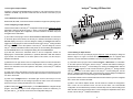
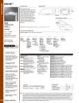
2.3.1 Hardware Configuration
Install any SCMD input module in any channel position 0 through 15. Connect an
appropriate discrete digital signal to the field I/O connectors (note: odd numbered screw
terminals are + connection) on the backpanel behind the module. See Figure 2.1. The
isoLynxTM Digital I/O Backpanel will demonstrate basic operation without any modules
installed as long as at least one input channel is configured.
5
isoLynxTM Digital I/O Backpanel
2.1 Unpacking
Each isoLynxTM Digital I/O Backpanel is shipped in electro-static discharge (ESD)
protective packaging. Use appropriate ESD protection measures while unpacking.
Check visually for physical damage. If physical damage is noted, file a claim with the
shipping carrier.
2.2 Package Contents and Physical Description
Figure 1.2
- isoLynxTM SLX101 Digital I/O Backpanel, two high speed serial I/O ports and 16 digital
I/O channel module sockets.
- One CD-ROM containing isoLynxTM data acquisition software drivers/examples and
documentation files including: Help files, manuals, and specifications.
- This isoLynx Digital I/O Backpanel Quick Start Guide.
TM
This completes the unpacking and visual inspection of the isoLynxTM Digital I/O
Backpanel.
The scope of the isoLynx Digital I/O Backpanel Quick Start Guide covers rapid
verification of the isoLynxTM Digital I/O Backpanel connected to an isoLynxTM Analog I/O
Base Unit only. For detailed configuration and installation in your system and for standalone operation, reference the isoLynxTM Hardware User Manual and/or the isoLynxTM
Software User Manual on CD-ROM.
TM
Figure 1.3
For rapid verification of basic functionality, continue with the next section.
(4) In the Input Options section, there are three choices: Single Shot, Repetitive and
Sample Interval. For a dynamic display, choose Repetitive. Sample Interval can range from
0.05 to 65.50 seconds.
(5) Clicking on the Input button will start data acquisition. Observe either the signal you
have connected or a random noise signal from the open analog input as a varying decimal
number next to the configured channel. The example in Figure 1.3 shows data for panel
0, channel 0. Click on the Stop button to stop data acquisition.
(6) Click on Disconnect, then X to end this demo.
1.3.3 Using isoLynxTM Commands Directly
Alternatively, you may use a terminal program, such as Hyperterminal in Win9x or later or
Terminal in Win3.1 to key in configure and input read commands. Reference the isoLynxTM
Software User Manual.
4
2.3 Verifying Basic Operation
At this point you are ready to insert an SCMD module, connect an external signal,
connect communications to the isoLynxTM Analog I/O Base Unit, and apply power to both
the isoLynxTM Analog I/O Base Unit and isoLynxTM Digital I/O Backpanel, and verify the
system's basic operation as follows:
2.3.1 Hardware Configuration
Install any SCMD input module in any channel position 0 through 15. Connect an
appropriate discrete digital signal to the field I/O connectors (note: odd numbered screw
terminals are + connection) on the backpanel behind the module. See Figure 2.1. The
isoLynxTM Digital I/O Backpanel will demonstrate basic operation without any modules
installed as long as at least one input channel is configured.
5
Install an SLX140-X cable (RJ45 both ends) between the isoLynxTM Analog I/O Base Unit
Digital I/O port (RJ-45) and one of the two RJ-45 Digital I/O ports on the isoLynxTM Digital
I/O Backpanel. These two ports are wired in parallel to allow chaining of multiple
isoLynxTM Digital I/O Backpanels, so it is not critical which one is used. See Figure 2.1.
See isoLynxTM Analog I/O Base Unit Section 1.3.1 for isoLynxTM to PC connection.
isoLynxTM Digital I/O Panel
Connect a +5VDC 1 Amp (minimum) power supply and turn on the power. Observe the
+5V LED lighting. Channel LEDs for populated channels may be on or off depending on
the state of the input. Channel LEDs for vacant channels will remain off. For location of
LEDs, see Figure 2.1.
2.3.2 Using PC Sample Software
Create the C:\Program Files\Dataforth\isoLynx folder on your local hard drive. From the
installation CD-ROM, copy the Demo folder and all of its contents to the folder you just
created.
2.3.2.1 Configuring an Input Channel
From the Demo folder run the isoLynxTM Configuration sample program Config.exe. Config
will display a dialog box similar to Figure 2.2. Figure 2.2 shows the Configuration Sample
dialog box as it appears after configuration, so some information and labels may have
changed from the initial states.
(1) The button at the top right corner is labeled Connect or Disconnect. For information
on the other options in this section, see the isoLynxTM Software User Manual. Clicking on
Connect displays an isoLynxTM Connect dialog box. Clicking on Connect within that box
triggers the Config program to make a serial connection to the isoLynxTM Digital I/O
Backpanel. For information on the other options in the isoLynxTM Connect dialog box, see
the isoLynxTM Software User Manual. After a short pause, the Connect dialog box
disappears and the Connect button in the Configuration dialog box shows Disconnect.
(2) At this time, observe the information boxes in the I/F Configuration section are
displaying the communication parameters, in particular, Baudrate: 9600 and Interface
Type: RS-232. For information on the other options in this section, see the isoLynxTM
Software User Manual.
(3) Observe the I/O Type boxes in the I/O configuration section have become activated.
Observe the box labeled I/O Panel shows the designation Aio.0, meaning: Analog I/O
Panel 0. Click on the down arrow button of the I/O Panel box. Click on Dio.0, meaning:
Digital I/O Panel 0, in the selection list. For information on the other options in this
section, see the isoLynxTM Software User Manual.
(4) Click on the down arrow button of the I/O Type box next to the channel you have
populated with a module. Select Di from the pull down list. Note the Channel Present box
now has a check mark.
6
Figure 2.1
(5) Click on the Configure button in the bottom right corner to send isoLynxTM its new
configuration. Click Yes in the I/O Configure question box. After a short communication
pause, the isoLynxTM Digital I/O Backpanel 0 is now configured and communicating with
the isoLynxTM Analog I/O Base Unit.
(6) Before running the Input sample program, you must Disconnect the Configure
sample program. The example in Figure 2.2 has configured panel 0, channel 0. At this
time, you may also click on
to minimize or X to close the Configuration dialog box.
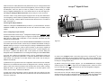
2.3.2.2 Reading an Input Channel
Next locate and run the Input sample program Input.exe. Input will display a dialog box
similar to Figure 2.3. Figure 2.3 shows the Input Sample dialog box as it appears after
execution, so some information and labels may have changed from the initial states.
7
Install an SLX140-X cable (RJ45 both ends) between the isoLynxTM Analog I/O Base Unit
Digital I/O port (RJ-45) and one of the two RJ-45 Digital I/O ports on the isoLynxTM Digital
I/O Backpanel. These two ports are wired in parallel to allow chaining of multiple
isoLynxTM Digital I/O Backpanels, so it is not critical which one is used. See Figure 2.1.
See isoLynxTM Analog I/O Base Unit Section 1.3.1 for isoLynxTM to PC connection.
isoLynxTM Digital I/O Panel
Connect a +5VDC 1 Amp (minimum) power supply and turn on the power. Observe the
+5V LED lighting. Channel LEDs for populated channels may be on or off depending on
the state of the input. Channel LEDs for vacant channels will remain off. For location of
LEDs, see Figure 2.1.
2.3.2 Using PC Sample Software
Create the C:\Program Files\Dataforth\isoLynx folder on your local hard drive. From the
installation CD-ROM, copy the Demo folder and all of its contents to the folder you just
created.
2.3.2.1 Configuring an Input Channel
From the Demo folder run the isoLynxTM Configuration sample program Config.exe. Config
will display a dialog box similar to Figure 2.2. Figure 2.2 shows the Configuration Sample
dialog box as it appears after configuration, so some information and labels may have
changed from the initial states.
(1) The button at the top right corner is labeled Connect or Disconnect. For information
on the other options in this section, see the isoLynxTM Software User Manual. Clicking on
Connect displays an isoLynxTM Connect dialog box. Clicking on Connect within that box
triggers the Config program to make a serial connection to the isoLynxTM Digital I/O
Backpanel. For information on the other options in the isoLynxTM Connect dialog box, see
the isoLynxTM Software User Manual. After a short pause, the Connect dialog box
disappears and the Connect button in the Configuration dialog box shows Disconnect.
(2) At this time, observe the information boxes in the I/F Configuration section are
displaying the communication parameters, in particular, Baudrate: 9600 and Interface
Type: RS-232. For information on the other options in this section, see the isoLynxTM
Software User Manual.
(3) Observe the I/O Type boxes in the I/O configuration section have become activated.
Observe the box labeled I/O Panel shows the designation Aio.0, meaning: Analog I/O
Panel 0. Click on the down arrow button of the I/O Panel box. Click on Dio.0, meaning:
Digital I/O Panel 0, in the selection list. For information on the other options in this
section, see the isoLynxTM Software User Manual.
(4) Click on the down arrow button of the I/O Type box next to the channel you have
populated with a module. Select Di from the pull down list. Note the Channel Present box
now has a check mark.
6
Figure 2.1
(5) Click on the Configure button in the bottom right corner to send isoLynxTM its new
configuration. Click Yes in the I/O Configure question box. After a short communication
pause, the isoLynxTM Digital I/O Backpanel 0 is now configured and communicating with
the isoLynxTM Analog I/O Base Unit.
(6) Before running the Input sample program, you must Disconnect the Configure
sample program. The example in Figure 2.2 has configured panel 0, channel 0. At this
time, you may also click on
to minimize or X to close the Configuration dialog box.
2.3.2.2 Reading an Input Channel
Next locate and run the Input sample program Input.exe. Input will display a dialog box
similar to Figure 2.3. Figure 2.3 shows the Input Sample dialog box as it appears after
execution, so some information and labels may have changed from the initial states.
7
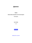
(1) The button at the top right corner is labeled Connect or Disconnect. For information on the
other options in this section, see the isoLynxTM Software User Manual. Clicking on
Connect displays an isoLynxTM Connect dialog box. Clicking on Connect within that
box triggers the Input program to make a serial connection to the isoLynx Digital I/O
Backpanel. For information on the other options in the isoLynxTM Connect dialog box,
see the isoLynxTM Software User Manual. After a short pause, the Connect dialog
box disappears and the Connect button in the Input dialog box shows Disconnect.
(2) At this time observe in the Channel Data section the channel you have configured
has a check mark. All others are blank.
(3) Note in the Channel Options section, the I/O Panel box as in Configure contains the
designation: Dio.0. There are four selection boxes, two have check marks and two are
de-activated. The recommended configuration is: Leave Read Group checked and
uncheck Stop On Error. Floating-Point Data and Average Data is de-activated for digital
panels. For the meanings and implications of the other choices, see the isoLynxTM
Software User Manual.
Figure 2.2
(4) In the Input Options section, there are three choices: Single Shot, Repetitive, and
Sample Interval. For a dynamic display, choose Repetitive. Sample Interval can range
from 0.05 to 65.50 seconds.
(5) Clicking on the Input button will start data acquisition. Observe either the signal you
have connected or a constant 1 or 0 next to the configured channel. The example in
Figure 2.3 shows data for panel 0, channel 0. Click on the Stop button to stop data
acquisition.
(6) Click on Disconnect, then X to end this demo.
2.3.3 Using isoLynxTM Commands Directly
Alternatively, you may use a terminal program, such as Hyperterminal in Win9x or later
or Terminal in Win3.1 to key in configure and input read commands. Reference the
isoLynxTM Software User Manual.
Figure 2.3
8
9
Warranty
General. Seller warrants that its products furnished hereunder will, at the time of delivery, be free from defects in material and workmanship and will
conform to Seller's applicable specifications or, if appropriate, to Buyer's specifications accepted in writing by Seller.
SELLER'S OBLIGATION OR LIABILITY TO BUYER FOR PRODUCTS WHICH DO NOT CONFORM TO THE ABOVE STATED WARRANTY
SHALL BE LIMITED TO SELLER, AT SELLER'S SOLE DISCRETION, EITHER REPAIRING, REPLACING, OR REFUNDING THE PURCHASE
PRICE OF THE DEFECTIVE PRODUCT(S) PROVIDED THAT WRITTEN NOTICE OF SAID DEFECT IS RECEIVED BY SELLER WITHIN THE
TIME PERIODS SET FORTH BELOW:
i. for all software products including licensed programs, thirty (30) days from date of initial delivery;
ii. for all hardware products including complete systems, one (1) year from date of initial delivery;
iii. for all special products, sixty (60) days from date of initial delivery; and further, all products warranted hereunder for which Seller has
received timely notice of nonconformance must be returned FOB Seller's plant within thirty (30) days after the expiration of the warranty
periods set forth above.
The foregoing warranties shall not apply to any products which Seller determines have, by Buyer or otherwise, been subjected to operating and/or
environmental conditions in excess of the maximum value established therefor in the applicable specifications, or any products that have been the
subject of mishandling, misuse, misapplication, neglect, improper testing, repair, alteration or damage.
Limitation. THE PROVISIONS OF THE FOREGOING WARRANTIES EXTEND TO BUYER ONLY AND NOT TO BUYER'S CUSTOMERS OR
USERS OF BUYER'S PRODUCTS AND ARE IN LIEU OF ANY OTHER WARRANTY, WHETHER EXPRESS, IMPLIED OR STATUTORY,
INCLUDING ANY IMPLIED WARRANTY OF MERCHANTABILITY OR FITNESS FOR A PARTICULAR PURPOSE. IN NO EVENT SHALL
SELLER BE LIABLE FOR INCIDENTAL, SPECIAL OR CONSEQUENTIAL DAMAGES.
Seller's liability arising out of the production, sale or supply of products or their use or disposition, whether based upon warranty, contract, tort or
otherwise, shall not exceed the actual purchase price paid by Buyer for Seller's products. Seller's liability for any claim of any kind shall in no case
exceed the obligation or liability specified in this Warranty.
Technical Assistance. Seller's Warranty as hereinabove set forth shall not be enlarged, diminished or affected by, and no obligation or liability shall
arise or grow out of, Seller's rendering of technical advice, facilities or service in connection with Buyer's order of the goods furnished hereunder.
Warranty Procedures. Buyer shall notify Seller of any products which it believes to be defective during the applicable warranty period and which
are covered by the warranty set forth above. Buyer shall not return any products for any reason without the prior authorization of Seller and issuance
of a Return Material Authorization number. After issuance of an RMA number, such products shall be promptly returned by Buyer (and in no event
later than thirty (30) days after the warranty expiration date), transportation and insurance prepaid, to the Seller's designated facility for examination
and testing. Seller shall either repair or replace any such products found to be so defective and promptly return such products to Buyer, transportation
and insurance prepaid. Should Seller's examination and testing not disclose any defect covered by the foregoing warranty, Seller shall so advise
Buyer and dispose of or return the products in accordance with Buyer's instructions and at Buyer's sole expense, and Buyer shall reimburse Seller
for testing expenses incurred at Seller's then current repair rates.
Repair Warranty. Seller warrants its repair work and/or replacement parts for a period of ninety (90) days from receipt by Buyer of the repaired or
replaced products or for the remainder of the warranty period for the initial delivery of such order as set forth above in paragraph a, whichever is
greater.
Critical Applications. Certain applications using Seller's products may involve potential risks of death, personal injury, or severe property or
environmental damage ("Critical Applications").
SELLER'S PRODUCTS ARE NOT DESIGNED, INTENDED, AUTHORIZED, OR WARRANTED TO BE SUITABLE FOR USE IN
LIFE-SUPPORT DEVICES OR SYSTEMS, SAFETY EQUIPMENT, NUCLEAR FACILITY APPLICATIONS OR OTHER CRITICAL APPLICATIONS
WHERE MALFUNCTION OF THE PRODUCT CAN BE EXPECTED TO RESULT IN PERSONAL INJURY, DEATH OR SEVERE PROPERTY
DAMAGE. BUYER USES OR SELLS SUCH PRODUCTS FOR USE IN SUCH CRITICAL APPLICATIONS AT BUYER'S OWN RISK AND AGREES
TO DEFEND, INDEMNIFY AND HOLD HARMLESS SELLER FROM ANY AND ALL DAMAGES, CLAIMS, SUITS OR EXPENSE RESULTING
FROM SUCH USE.
Static Sensitive. Seller ships all product in anit-static packages. Seller's Warranty as hereinabove set forth shall not cover warranty repair,
replacement, or refund on product or devices damaged by static due to Buyer's failure to properly ground.
Application Support. Dataforth provides timely, high-quality product support. Just call 1-800-444-7644 TOLL-FREE (USA)
Returns/Repair Policy. All warranty and repair requests should be directed to the Dataforth Customer Service Department at (520) 741-1404. If a
product return is required, request a Return Material Authorization (RMA) number. You should be ready to provide the following information:
1. Complete product model number.
2. Product serial number.
3. Name, address, and telephone number of person returning product.
4. Special repair instructions.
5. Purchase order number for out-of-warranty repairs.
The product should be carefully packaged, making sure the RMA number appears on the outside of the package, and ship prepaid to:
Dataforth Corporation
3331 E. Hemisphere Loop
Tucson, AZ 85706 USA
Phone: 520-741-1404
FAX: 520-741-0762
The information provided herein is believed to be reliable; however, DATAFORTH assumes no responsibility for inaccuracies or omissions.
DATAFORTH assumes no responsibility for the use of this information, and all use of such information shall be entirely at the user's own risk.
Application information is intended as suggestions for possible use of the products and not as explicit performance in a specific application. Prices
and specifications are subject to change without notice. No patent rights or licenses to any of the circuits described herein are implied or granted to
any third party. DATAFORTH does not authorize or warrant any DATAFORTH product for use in life support devices and/or systems.
MA1016
SLX100/101
Quick Start Guide