1
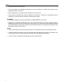
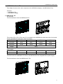
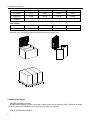
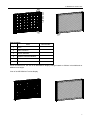
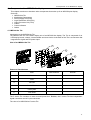
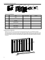
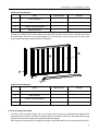
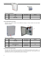
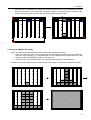
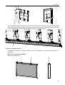
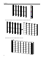
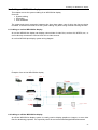
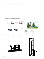
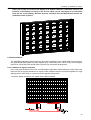
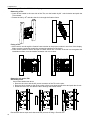
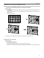
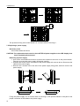
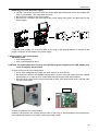
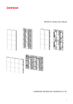
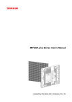
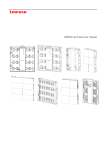
IMPOSA lite Series User’s Manual
Version 1.1
Table of Contents
Table of Contents
1. Safety
1.1 Guidelines
1.2 Safety instructions
2. IMPOSA lite Series Tiles
2.1 IMPOSA lite Tile
2.2 IMPOSA lite display
3.
3.1
3.2
3.3
Installation requirements
Mechanical requirements
Electrical requirements
System requirements for the Control software
4.
4.1
4.2
4.3
4.4
4.5
4.6
4.7
4.8
Components of an IMPOSA lite display
IMPOSA lite Tile
Mechanical Components
Power Supply Unit
LDU
Video Processing Unit
Cables
Control software
Others
5. Installation
5.1 Preparing the back supporting structure
5.2 Mounting the extrusion frame
5.2.1 Assembling the extrusion frame
5.2.2 Mounting the frame
5.3 Fixing the IMPOSA lite display
5.4 Other mounting methods
6. Cabling an IMPOSA lite display
6.1 Cabling an on-line IMPOSA lite display
6.2 Cabling an off-line IMPOSA lite display
6.3 Pixel limitations
7. Maintenance
7.1 Firmware update
7.1.1 LDU firmware update
7.1.2 Tile control board firmware update
7.2 Replacing a Tile of an IMPOSA lite display
7.3 Replacing a Tile of a front serviced IMPOSA lite display
7.4 Replacing a Tile control board
7.5 Replacing a power supply
7.6 Replacing a LDU control board
8. Trouble shooting
9. Specifications
9.1 IMPOSA lite VFI series display specifications
9.2 Dimensions of an IMPOSA lite display
9.3 Weights of IMPOSA lite display parts
10. Part Numbers of IMPOSA lite display parts
1
2
1.Safety
1. Safety
Before installing an IMPOSA lite display, one is required to read this chapter carefully to obtain
important information as to how to prevent personal injury and to protect the display from damage
during installation.
Overview
§ Guidelines
§ Safety instructions
1.1 Guidelines
§ Before installing the display, make sure you have read the User’s Manual with full understanding.
§ Installation must be performed by authorized and qualified technical personnel only.
§ The installation site must be solid and without any chance of sinking, tumbling or falling. It must be at
the same time free of over-heat, radiation, pollution, corrosion or gas release.
§ Only use components provided by the Manufacturer or those approved or specified by the
Manufacturer during installation of IMPOSA lite series displays.
§ Do not modify and/or replicate any component or accessory without permit from the Manufacturer.
§ Always follow all installation instructions. Please contact the Manufacture if any problem arises.
Special attention should be paid to all “CAUTION” and “TIPS” mentioned in this User’s Manual which
respectively intends:
CAUTION: to draw operators’ attention to an important instruction or to remind them of what
might happen.
TIPS: to give advice on how to perform an operation better.
1.2 Safety instructions
Product care
§ All parts must be fully protected and packed in good order during transportation, storage, etc. No
external pressure shall be applied on them.
§ No part of the product can come into contact with rain before or during installation. Keep them in dry
and clean places.
§ All parts must be prevented from being trampled, stroke or dropped. Follow all instructions while
carrying or moving the parts. Otherwise the product can be subject to terminal damage.
Installation
§ Before installation, ensure that the supporting structure or frame has sufficient strength to hold the
display firm and safe.
§ For hoist installation, the operator must follow all instructions given in this User’s Manual, including
where the hoist brackets should be located, that the crane used must come with sufficient capability
to hoist the product, and that the operating ground must have the strength to sustain the crane, etc.
§ Most components of the product are heavy. Therefore high attention should be paid to personnel
safety during installation.
§ All connection bolts must be fastened firmly and securely.
Power
§ An IMPOSA lite display is to be powered by a 3-phase power with 5 lines. That is, it must come with
an independent neutral line and an independent ground line.
§ Provide the power and power supply circuits in accordance with the power consumption of the
display. All circuits must come with protection tubes and confirm with the local electrical safety
standards.
§ The LDU and PSU must be installed near the display. Cables from the LDU and PSU to the display
3
1.Safety
cannot be stretched or impaired. Power distribution from the PSU to the display cannot exceed what
is required by this User’s Manual.
§ The input voltage of an IMPOSA lite display can be set at 120VAC or 220VAC. But ensure to set it
right before power connection.
§ Do not attempt to fix an impaired cable. Replace it with a new one.
§ A big current is produced the moment a display is powered on. Therefore an air breaker that can
sustain big currents should be used as the master power switch.
Grounding
§ IMPOSA lite displays must be grounded with an INDEPENDENT ground wire.
§ Displays to be installed independently from any architectural structure must be equipped with an
independent ground wire and, if necessary, a lightning rod. The down lead of the lightning rod should
be insulated with the frame of the display. Set the earth electrode of the lightning rod and that of the
ground wire away from each other.
Usage
§ LEDs on the display cannot be pressured at any time. Otherwise they can be damaged for good.
4
§
Follow the steps mentioned in this User’s Manual while cleaning the front side of the display. Only
soft clothing or brush, neutral detergent and water are to be applied to the display.
§
Power must be cut off before dismantling any part for maintenance.
2.IMPOSA lite Series Tiles
2. IMPOSA lite Series Tiles
This chapter focuses on the main component of an IMPOSA lite display---the IMPOSA lite Tiles.
Overview
§ IMPOSA lite Tile
§ IMPOSA lite Display
2.1 IMPOSA lite Tile
Tile overview
The front and back view of an IMPOSA lite tile
The models VFI6, VFI8, VFI9.6 and VFI12 included in the IMPOSA lite series have tiles of the same
size but with different resolutions. Please see below:
Tile
VFI6
VFI8
VFI9.6
VFI12
Pixel pitch
6mm
8mm
9.6mm
12mm
Resolution
64X48
48X36
40X30
32X24
VFI9.6 Tile
VFI12 Tile
Weight
2.8kg
Part Number
Tile
VFI6 Tile
VFI8 Tile
Part Number
The other series, the IMPOSA lite P series, uses IMPOSA lite Tiles integrated with a power supply.
The front and back view of an IMPOSA lite P Tile
5
2.IMPOSA lite Series Tiles
Parameters of IMPOSA lite P series models
Tile
VFI6P
VFI8P
VFI9.6P
VFI12P
Pixel pitch
6mm
8mm
9.6mm
12mm
Resolution
64X48
48X36
40X30
32X24
VFI6P Tile
VFI8P Tile
VFI9.6P Tile
VFI12P Tile
Weight
Part Number
Tile
Part Number
Package of the IMPOSA lite series and the IMPOSA lite P series Tiles
2.2 IMPOSA lite display
IMPOSA lite display overview
An IMPOSA lite display is made of a certain number of tiles and an extrusion frame. Thanks to its simple
structure, cabling and installation of the display can be done in a breeze.
View of an IMPOSA lite display
6
2.IMPOSA lite Series Tiles
6
1
4
2
5
3
Part Numbers
Parts
1
Tiles
2
Main extrusion
3
Cover extrusion
4
Column extrusion Module
5
Nut block
6
Eyebolt set
Part Number
Given its module size, the size of an IMPOSA lite display changes based on 384mm in its width and on
288mm in its height.
View of an IMPOSA lite P series display
7
2.IMPOSA lite Series Tiles
8
3. Installation requirements
3. Installation requirements
This chapter covers requirements for installation, power supply and the control system of an IMPOSA
lite display.
Overview
§ Mechanical requirements
§ Electrical requirements
§ System requirements
3.1 Mechanical requirements
An IMPOSA lite display comes with its own structural frame which makes installation simple and easy.
Besides, it requires a strong and reliable supporting frame at the back to hold the display firm.
Wherever this supporting frame is to be installed, on the ground, onto the pole or on a wall, attention
should be paid to the following few points:
1. The display should be installed in a place that allows a clear and complete view of the display.
2. The supporting frame has to be strong enough to prevent the display from tumbling.
3. The installation site must have the strength to withstand the total weight of the display plus its
structural frames.
4. The IMPOSA lite display is meant for indoor use only. The ambient temperature, dust and ventilation,
esp. that at the back of the display must be considered when one is choosing the installation site.
A typical way of mounting an IMPOSA lite display onto a wall:
3.2 Electrical requirements
Power requirements
§ An IMPOSA lite display works on AC 200-240V, 50~60Hz. Each column of the display has an
independent power supply circuit and can thus be powered by electricity from different phases.
§ When the max. power consumption of an IMPOSA lite display is less than 3KW, the display can
be powered by single-phase power supply circuits which include a live, neutral and ground wire.
Each circuit is controlled by an independent air-break switch.
§ But if the maximum consumption of the display is over 3KW, it should be powered by 3-phase
power supply circuits c/w a live, neutral and ground wire. The 3-phase power distributes power to
tiles of each column on an average level. A PSU (power supply unit) is used to control the power.
§ The IMPOSA plus block can also be powered by AC100-125V, 50~60Hz power supplies. But this
needs to be specified in the production order so that it can be pre-set before going out of factory.
9
3. Installation requirements
Grounding
The IMPOSA lite display shall be grounded at the installation site. If the existing power supply circuit
cannot provide a good ground wire or does not even have one, it’s a must to set or reset a reliable
ground wire for the display. Good grounding will enable the display to work properly and can prevent it
from being disturbed by surge.
3.3 System requirements for the Control software
When the Windows System is in question:
PC System requirements:
§ CPU Pentium IV or equivalent, 2.4GHz
§ 1 GB DDR RAM
§ Free hard disk space 300MB
§ Resolution 1280x1024 with 32M video memory
§ DVI port
§ Ethernet connection
§ Windows XP Professional or Windows Vista
10
4.Components of an IMPOSA lite display
4. Components of an IMPOSA lite display
This chapter continues to introduce other components that make up of an IMPOSA plus display.
Overview
§ IMPOSA lite Tile
§ Mechanical Components
§ Power Supply Unit (PSU)
§ Logic Distribution Unit (LDU)
§ Video Processor Unit (VPU)
§ Cables
§ Control software
§ Others
4.1 IMPOSA lite Tile
Introduction to the IMPOSA lite Tile
The IMPOSA lite Tile is the basic display unit of an IMPOSA lite display. The Tile is composed of an
LED display board, a mask, a control board and some locks. At the back of the Tile is a connector that
integrates the signal and DC power input.
View of an IMPOSA lite Tile
1
2
3
4
5
6
Parts and Part Numbers
Parts
1
Mask
2
PCB
3
Tile base
4
Control Board
5
Cover plate
6
Lock head
Part Numbers
Remark
The P series Tile includes an extra covered power box. Besides, the P series Tile has independent
signal connectors and AC input connectors.
The view of an IMPOSA lite P series Tile
11
4.Components of an IMPOSA lite display
1
2
3
4
5
7
6
Parts and Part Numbers
Parts
1
Mask
2
PCB
3
Tile base
4
Control Board
5
Cover plate
6
Power Supply
7
Power cover
Part Numbers
Remark
4.2 Mechanical Components
Besides the tile, there are some structural components that help make up an IMPOSA lite display.
The main extrusion is the structural frame of an IMPOSA lite display, while the cover extrusion is used
as a decorative frame to the front of the display. The pole structure is the supporting frame where tiles
are to be mounted. It also comes with switch power supplies, power and signal circuits and connectors
to the tiles.
3
4
2
1
12
4.Components of an IMPOSA lite display
Eyebolts are used for hoist installation of the display. They can be removed after installation.
Parts and Part Numbers
Parts
1
Cover extrusion
2
Main extrusion
3
Column extrusion Module
4
Signal connector
Part Numbers
Remark
Similarly, the IMPOSA lite P series display uses the main extrusion and the cover extrusion as its main
structural frame. But there is no power supply in its pole structure. Inside it there are only AC power
supply cables and signal cables and their connectors.
Parts and Part Numbers
Parts
1
Cover extrusion
2
Main extrusion
3
Column extrusion Module
4
Column pole
Part Numbers
Remark
4.3 Power Supply Unit (PSU)
The PSU, short for Power Supply Unit, is the power control center for an IMPOSA lite display. Each
output channel of the PSU controls one column of tiles of a display. The PSU is also inbuilt with a surge
protector to prevent the display from being disturbed by lighting.
But if the power consumption of a display is not high, an air-break switch can be used in place of a PSU.
13
4.Components of an IMPOSA lite display
Parts and Part Numbers
Parts
1
PSU
2
Air breaker
Part Numbers
Remark
4.4 Logic Distribution Unit (LDU)
The LDU is the central controller for the IMPOSA lite display. It mainly includes the control board
QS5800 or QS5003.
Parts and Part Numbers
Parts
Part Numbers
Remark
1
LDU3000
381-100201
2
Control board (QS5800)
380-200202
QS5800
3
Power supply (5V)
380-200102
5V
4
Fan
380-200302
4.5 Video Processing Unit (VPU)
The VPU is the video and DVI sync processor in the IMPOSA synchronous control system. It is
compatible with various video signal inputs as well as the DVI signal input. These signals are then
transmitted to the LDU via an optic fiber and shown on the display.
14
4.Components of an IMPOSA lite display
Instrutuion
Parts
1
Power switch
2
LCD screen
3
Menu
4
Shortcut key to other Video Sources
5
Shortcut key to DVI Input
4.6 Cables
Signal cable between LDU and Tiles
DVI cable
Fiber cable
Power cable between PSU and Tiles
Network cable
USB cable
4.7 Control software
15
4.Components of an IMPOSA lite display
The series of control software developed by Imposa itself are meant for system setting, test and
display control of an IMPOSA lite display.
TIPS: Please refer to the user’s manual of each control software for more information about their
functions and use guidance.
IMPOSA Tool
IMPOSA Tool is the tool software for the LDU to set up, configure, manage and test the display.
Sigma 3000
Sigma 3000 is a powerful control software for an offline system. It can be used to set up, configure the
display as well as control, manage, test and record what is shown offline on the display.
LED Net
16
4.Components of an IMPOSA lite display
VPU 3400 is the setup and control software for the VPU. It’s used to manage and control the
synchronous display of various videos inputs on the display and as always, system setup.
4.8 Others
To complete the control system, an IMPOSA lite display may also require some other accessories, say
a computer installed with various video or picture tailoring or editing software, etc.
If the synchronous system is in question, extra video devices like a Camera, a Record disc, a set of
audio equipment including a prime amplifier, a power amplifier and a voice box, etc. are requires as
well.
All the accessories mentioned above are to be provided by the user on their own based on actual
applications.
An IMPOSA lite display with the synchronous system
18
5.Installation
5. Installation
This chapter describes the various installation methods of an IMPOSA lite display.
Overview
§ Preparing the supporting back structure
§ Mounting the extrusion frame
§ Fixing the IMPOSA lite Tile
§ Other types of supporting structure
5.1 Preparing the back supporting structure
Connect the top and bottom main extrusion of an IMPOSA lite display to its back supporting structure
by connection plates. This is usually how the display is installed.
Typical mounting of an IMPOSA lite display:
The back supporting structure is usually built on a wall or sits on a pole on the ground. Depending on
the size of the display and space available installation site, there can actually be many ways of
preparing the supporting structure.
Below are some typical back supporting structures for clients’ reference:
19
5.Installation
CAUTION: If the display is to be mounted on a wall, one has to consider the withstanding capability
of the wall. In such a case, it’s usually advised to install the display onto the structural
column of the wall.
TIPS:Connection positions on the back supporting structure must match those on the IMPOSA lite
display. The manufacturer can provide the back supporting structure or the connection part
for the client, but only on the condition that the client fully informs the manufacturer of
conditions in the installation site.
5.2 Mounting the extrusion frame
After mounting the tiles, installation of other structural frames are to follow.
5.2.1
Assembling the extrusion frame
Necessary tools
§ 8mm open-end wrench
§ 8mm box-end wrench
§ 8mm hexagonal key
§ 6mm Cross head screw driver
§ Modular tool
20
5.Installation
Connect the 4 sides of the main extrusion on a flat ground. Insert corner blocks onto the connection
positions of the main extrusion. Screw them in a loose manner.
Mount the pole extrusions in the middle of the frame and mount their screws. With the aid of a Modular
tool, find the right position for the screws and screw them tight. Then screw the 4 corners of the Main
extrusion tight.
CAUTION: All screws on the frame must be fastened when installation is finished.
5.2.2 Mounting the frame
Necessary tools
§ 12mm open-end wrench
§ 12mm box-end wrench
§ 6mm Cross head screw driver
§ A Crane
Hoist and fix the finished frame onto the back supporting structure. Keep an eye on the horizontal and
vertical condition of the frame as well as the flat surface of the tiles. Make sure everything is in good
21
5.Installation
condition.
TIPS:In occasions where the installation site doesn’t allow use of a Crane while the frame is too big
for human operation, one can try the following installation method:
§ Mount the top horizontal Main extrusion onto the back supporting structure and fasten the
screws.
§ Then mount the Main extrusions on both sides and fasten their tops with the top horizontal
extrusion.
§ Lay the Pole extrusions in place. Screw their tops with the top horizontal extrusion in a loose
manner.
§ After all the Pole extrusions and the side Main extrusions have been installed and hang vertically,
22
5.Installation
one can start to mount the Main extrusion on the bottom.
§ With the aid of a Modular tool, fasten the screws on the top of the Pole extrusions and then
those at the bottom. Then fasten the connection screws of the bottom Main extrusion. Last,
connect the bottom Main extrusion with the back supporting structure fast.
5.3 Fixing the IMPOSA lite display
Before mounting the display, attention must be paid to the following few things:
§ Make sure that the frame of the display has been properly connected with the supporting
structure, that everything is in good condition on the horizontal and vertical direction of the
display and that the installation surface is flat and even.
§ Check if the tiles are installed in their exact positions with the help of a Modular tool.
Installation of the tiles starts from the middle column from bottom to top and then towards both sides.
23
5.Installation
How to fix tiles onto the frame:
There is a handle at the back of each tile. Before mounting a tile, turn its handle by 90°anti-clockwise
to draw back the locks at the back of the tile. Lay the tile in its exact position. Make sure connectors on
the tiles match those on the pole extrusion. Turn the handle by 90°clockwise to lock the tile firm on
the pole extrusion.
On the other hand, a P series tile is fixed onto the pole structure with 4 M6X12 screws at its back.
While fixing the tile, one must make sure the connectors match the connection positions on the pole.
After all tiles have been mounted, cover the pole extrusions with cover plates.
CAUTION: For a front-serviced display whose back is unapproachable, cables must be connected
before the tiles are mounted.
TIPS: One can stand in front of a front-serviced display and reach his hand to the back of the tiles
to operate on their handles so as to mount them. However, he has to operate by putting his
hand between the wall and the display to mount the last tile.
Therefore some space must be kept between the wall and a front-serviced display, so that
one can easily put his hand in to mount or maintain the last tile.
24
5.Installation
After all tiles have been mounted, it’s time to mount the Cover extrusions. Fix the Cover extrusions
with the Main extrusions with M4X12 screws. Or one can drill holes on both extrusions with a drill that
has a 3.5mm bit and then use 4mm self-tapping screws to fix them together.
5.4 Other mounting methods
An IMPOSA lite display can also be installed in other ways depending on clients’ actual application of
the display.
Below are some typical examples:
Hanging the display in air
25
5.Installation
Mounting a frame less display against a wall or into a groove on the wall
Mounting the display onto an arc-shaped wall with a minimum radius of 8m
Special side covers to be installed inside a voice box
26
6.Cabling an IMPOSA lite display
6. Cabling an IMPOSA lite display
This chapter covers the system cabling of an IMPOSA lite display.
Overview
§ System cabling
§ Grounding
§ Pixel limitations
The power and signal connection between tiles have been taken care of while the tiles are being
mounted. Therefore one needs to do the system cabling only after having finished mounting the tiles.
6.1 Cabling an on-line IMPOSA lite display
An on-line IMPOSA lite display can display various kinds of video files, such as AVI, MPEG2, etc., or
can be directly connected to various kinds of live video sources.
An on-line IMPOSA plus display system wiring diagram
Example of an on-line IMPOSA lite display
6.2 Cabling an off-line IMPOSA lite display
An off-line IMPOSA lite display system is usually used to display graphics or images, or even video
files for advertising purposes. It is especially useful for an interconnected digital billboard network.
27
6.Cabling an IMPOSA lite display
An off-line IMPOSA plus display system wiring diagram
Example of an off-line IMPOSA lite display
TIPS: The LDU has to be laid close to the display. It can be put behind the display or somewhere
else nearby. The signal cables and power cables of the tiles can be hidden inside the Main
extrusions.
28
6.Cabling an IMPOSA lite display
TIPS: Signal cables from the LDU and power cables from the PSU (or directly from commercial
power) are usually connected to the display at its bottom. However, if otherwise required, for
instance, if the display is to hang in the air, the cables can be rearranged to be connected
from the top of the display. But this must be specified with the Manufacturer before the
production order is placed.
6.3 Pixel limitations
The IMPOSA lite display system supports a dot matrix resolution of up to 1920X1080 pixels. However,
the signal distribution system LDU only supports up to 1024X768 pixels. That is to say, an LED display
larger than 1024X768 pixels would need a special LDU connection arrangement.
6.3.1 Limitation of signal connection
Due to the pixel limitation of the LDU, an LED display larger than 1024X768 pixels would need more
than one LDU to support distribution of signals. When multiple LDUs are connected together, the right
starting point of each LDU on a picture must be appointed and preset.
Example: Signal connection of a display with 1280X768 pixels
29
6.Cabling an IMPOSA lite display
6.3.2 Limitation of power connection
As a rule, each column of tiles of an LED display is connected by an AC power cable to the PSU for
power supply. However, if the display is extremely large and comprises of more tiles than could be
supplied by one power cable due to current restriction, it becomes necessary to use multiple power
supply cables which need to be connected to different power output terminals at the PSU.
Example: Power supply connection of a display with 960X600 pixels
30
7.Maintenance
7. Maintenance
Overview
§ Firmware update
§ Replacement a Tile of IMPOSA lite display
§ Replacement a unit control board
§ Replacement a power supply
§ Replacement a LDU control board
7.1 Firmware update
Control boards in both LDU and display unit may need firmware updating in actual use.
7.1.1
LDU firmware update
There are 3 ways to update the firmware on the control board QS5800 in the LDU:
1. Use the update package QS5800_update packet_verxx.xx_(year/month/date).rar to update the
firmware
Steps: connect the display to a PC via an Ethernet cable, decompress the package in the PC,
and double click the update.bat in the file to start the automatic update process.
2. Use the update package QS5800_update packet_verxx.xx_(year/month/date) (for USB).rar to
update the firmware
Steps: decompress the package in a USB disk, connect the disk to the QS5800 control board
and the update process will start automatically.
3. Use the update file xxxx.cpu.
Steps: Log onto the software Sigma 3000, choose Tool---Update---Update CPU and then select
the file xxxx.cpu to start the update process.
7.1.2
Updating the display unit controller firmware
There is a QS5242 control board inside the power box of each Unit. Following steps shall be
observed to update the firmware on these control boards:
Log on the software IMPOSA Tools and choose “Maintenance” where you can choose a certain Unit
address or choose All Units for updating the firmware on their control boards.
Select the following files in sequence for updating:
File xxx.bin -----the CPU program for the control board. You can find it in the File Style menu
presented as “CPU program for tiles”;
File xxx.bin -----the data file of the control board. It can be found in the File Style menu presented as
“Drive Board data”;
File xxx.rbf -----the FPGA program for the control board, presented as “FPGA for tiles” in the File Style
menu;
File xxx.rbf -----the gamma data of the control board which can be seen as “Gamma Data for tiles” in
the File Style menu;
File xxx.bin -----the brightness data of the control board, presented as “Brightness Block of tiles” in
the File Style menu.
TIPS:In order to make it convenient for the operator, a few definitions are given below for operation
of the screws.
Unfasten:It means loosening the screw halfway. Do not unfasten completely or remove the
screw.
Unscrew:It means completely unfastening the screw. But because the screws are of an
un-detachable type, there is no need to worry about the screw dropping to the
ground.
Remove:It means removing the screw completely. Care should be taken of not to let the
screw drop to the ground or get lost.
31
7.Maintenance
7.2 Replacing a Tile of an IMPOSA lite display
Removing a Tile:
§ Catch at the handle in the rear side of the Tile, turn the handle by 90°anti-clockwise and push the
Tile outward.
§ Rotate the tile by 45o and take the tile in through the fixation frame.
Fixing a Tile:
§ Move the tile out through the fixation frame window to the proper location in the front of the display.
Make sure the connectors match the connection positions on the frame.
§ Catch at the handle of the tile and pull it inward. When the 4 corners of the tile is even against the
installation surface, turn the handle clockwise until it is leveled.
Removing a P series Tile:
Necessary tools
6mm cross head screw driver
§ Remove the cover and the AC power connector of the Tile on the pole.
§ Remove the 4 screws on the tile by using a 6mm cross head screw driver and push the tile out.
§ Rotate the tile to 45o and take the tile in through the fixation frame.
Reverse the above steps and it becomes the process of fixing a P series Tile.
32
7.Maintenance
7.3 Replacing a Tile of a front serviced IMPOSA lite display
TIPS: For a front serviced IMPOSA lite display, some space must be kept so that one can reach his
hand to the back of the display to mount or maintain the nearest tile.
Removing a Tile:
§ One can reach his hand from the side of the display to remove the nearest approachable tile to
the target tile.
§ Remove all the other tiles one by one through the left out fixation window until the target tile can
be accessed.
§ Remove the target tile.
Fixing a front serviced IMPOSA lite display tile is reversed to its removing process.
7.4 Replacing a Tile control board
Necessary tools
6mm cross head screw driver
§ Removing the control board:
§ Lay the tile. Unscrew the 4 screws on the tile and remove the cover.
§ Remove the 5 screws on the control board and take the control board off in the vertical direction.
33
7.Maintenance
The process of fixing a tile control board is in a reverse order of removing it.
7.5 Replacing a power supply
Necessary tools
6mm cross head screw driver
CAUTION: The replacement work must be done AFTER all power supplies to the LED display have
been completely disconnected.
Removing a power supply:
§ Use a 6mm cross head screw driver to remove the screws on the cover on the pole extrusion.
Take the cover and the power supply off the pole carefully.
§ Unfasten the screws on the connectors of the power supply with a screw driver. Disconnect the
cables to the power supply.
§ Remove the 4 screws in the rear side of the power supply fixing plate, and then remove the
power supply.
Fixing the power supply is in a reverse order of removing it, with special attention to be paid to the
proper connection of the cables to the power supply.
34
7.Maintenance
Replacing a P series tile power supply:
§ Lay the P series tile, remove the 2 screws on the upper part of the power cover and unfasten the
other 2 at its bottom. Then take down the cover.
§ Disconnect the cables to the power supply.
§ Remove the 4 screws in the rear side of the power supply fixing plate, and then take out the
power supply.
Fixing the power supply is in a reverse order of removing it, with special attention to be paid to the
proper connection of the cables to the power supply.
7.6 Replacing an LDU control board
Necessary tools
§ 6mm hexagonal key
§ 6mm cross head screw driver
CAUTION: The replacement work must be done AFTER all power supplies to the LED display have
been completely disconnected.
Process to remove an LDU control board:
§ Use a 6mm hexagonal key to open the open the door on the LDU box.
§ Disconnect the wires to the QS5800 control board. Check if the signal output wires are marked
with numbers. If no mark is seen, please label the output signal wires with numbers.
§ Remove the 4 screws on the control board with a 6mm cross head screw driver, and then take
out the control board.
QS5800
Process to install an LDU control board:
Install the LDU board in the reverse process order of removing it. Special attention should be paid to
the location and method of connection of the signal output wires.
35
8.Trouble shooting
8. Trouble shooting
This chapter introduces some possible trouble symptoms and their remedial treatment to the IMPOSA
lite display.
TIPS: If a problem is seen on an LED display and its cause is hard to diagnose, please write down a
description of the symptom as detailed as possible, take some pictures and report to the
Manufacturer for help.
CAUTION: Before any operation on the PCB or any wire connection is carried out, all power
supplies to the LED display MUST be completely disconnected. When doing wire
connection, please make sure all wires have been connected properly and securely.
Symptom
36
Cause Analysis
Remedy
One tile is not displaying.
§ Cables connected to the tile get
loose.
§ Program or data on the tile control
board get lost.
§ Something is wrong with the tile
itself.
§ Check the connectors and the
signal cables of the tile.
§ Update the CPU program or
data on the tile.
§ Replace the tile.
A small segment of the tile is
not displaying the right color,
or the segment is
uncontrollable.
§ Something is wrong with the tile
itself.
§ Replace the tile.
One tile keeps displaying the
address number.
§ The signal cable to the tile is not
connected well.
§ Firmware on the tile controller is
impaired.
§ Tile controller is broken.
§ Connect the signal cable to the
tile properly and securely.
§ Update the CPU program or
data on the tile.
§ Replace the tile controller.
One unit shows a different
color or brightness from the
surrounding units.
§ The gamma data on the tile
controller are different from those
on other tile controllers.
§ The brightness data on the tile
controller are different from those
on other tile controllers.
§ Check the gamma data of the
tile in IMPOSA Tools and set
them same as those on other
controllers.
§ Update the brightness data on
the tile controller or set them to
be same as those on other
controllers.
A whole patch above a
certain tile in a column goes
completely dark.
§ Either the power supply or the
cable connection of the failed tile at
§ Check the power supply and the
the lowest position needs to be
power cable of the tile. Correct
fixed.
or replace them if necessary.
§ The signal cable connecting to the
§ Check the cable connection on
failed tile at the lowest position
the tile controller. Connect them
hasn’t been properly connected.
properly.
§ The control board of the failed tile
§ Replace the tile controller.
at the lowest position may be
impaired.
One column of tiles goes
completely dark.
§ Check the power cable and
§ There is no power into this column.
power connector of the column.
§ There is no signal into this column § Check the connectors at both
of tiles.
ends of the signal cables of the
column.
8.Trouble shooting
One column of the display
keeps showing random
contents.
§ The signal cables on this column
are not connected well.
§ Check the connectors at both
ends of the signal cables of the
column.
The whole LED display goes
dark.
§ There is no power in at all.
§ The power supply or the control
board in the LDU failed to work
properly.
§ There is no display content
available.
§ Check if there is indeed power
input.
§ Check the power supply and the
control board in the LDU.
Replace them if necessary.
§ Send display contents to the
display.
37
9.Speciflcations
9. Specifications
The chapter lists main parameters of an IMPOSA lite display and those of its components.
Overview
§ IMPOSA lite VFI series display specifications
§ Dimensions of an IMPOSA lite display
§ Weights of IMPOSA lite parts
9.1 IMPOSA lite VFI series display specifications
Pixel pitch
VFI6
VFI8
VFI9.6
VFI12
6mm
8mm
9.6mm
12mm
LED configuration
Tile physical resolutions
RGB 3in1 Chip LED
64X48
Colors
Brightness
2200 nit
Temperature range
2000 nit
27,778/m 2
2,582/ft2
15,625/m 2
1,452/ft2
10,851/m 2
1,008/ft2
1500 nit
6,944/m 2
645/ft2
> 1000 Hz
max.120W/Tile
max.120W/Tile
max.100W/Tile
-20 ~ 40 oC ( -4 ~ 104 oF )
40% ~ 95%
Lifetime
Compositive 100,000 Hours
Tile weight
38
2000 nit
Humidity
Tile dimensions
32X24
Horizontal 140o Vertical 120 o
Refresh rate
Power consumption
40X30
14 bit each color
Viewing angle
Pixel density
48X36
384mm X 288mm ( 15.1” X 11.3” )
2.9kg (6.4lbs); Tile : 3.9kg (8.6lbs)
max.100W/Tile
9.Speciflcations
9.2 Dimensions of an IMPOSA lite display
Dimensions of a Tile
288
114
Dimensions of a sample IMPOSA lite display
114
114
384
114
209
39
9.Speciflcations
9.3 Weights of IMPOSA lite display parts
Main assembling parts of an IMPOSA lite display
7
6
8
1
Series
3
Parts
1
Tile
2
Main extrusion
3
Column extrusion Module
4
Cover extrusion
5
Support structure
6
End cover
7
Power supply
8
Connect block
9
10
40
2
4
Weight
5
9.Speciflcations
10. Part Numbers of IMPOSA lite display parts
Part Number
Parts
41