1
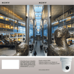
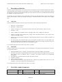
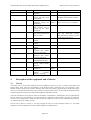
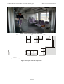
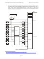
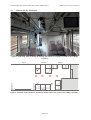
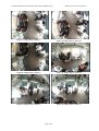
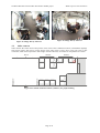
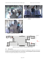
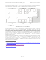
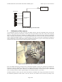
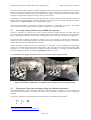
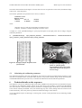
On Board Wireless Secured Video Surveillance: BOSS project
BOSS sequences documentation
BOSS: ON BOARD WIRELESS SECURED VIDEO SURVEILLANCE
BOSS SEQUENCES
Contractual Date of Delivery to the Celtic Office:
Actual Date of Delivery to the Celtic Office:
Editor(s): Jean-Luc Bruyelle, Kaori Hagihara
Participant(s): UCL
Workpackage: WP5
Deliverable nature and security level: Dissemination document, public
Version: 1.0
Revision Date:
Total number of pages: 21
Abstract:
This document describes the audio/video sequences uploaded to the public part of the project’s web site,
containing acted incidents and other scenarios considered in the framework of the BOSS project. It provides,
beside the list and contents description of the sequence themselves, information regarding the way they were
obtained (among other things, the locations and types of the sensors), and an user manual of how to actually use
them, most notably information regarding the calibration.
For some sequences, ground truth is also provided. This document contains the events of interest that were acted
in the sequences, and the format of the files describing the events occurring in those sequences.
Keyword list:
BOSS, sequences, audio, video, dissemination, train
Page 1/21
On Board Wireless Secured Video Surveillance: BOSS project
1
DEFINITION OF THE SCENARIOS OF INTEREST............................................................................. 3
1.1
1.2
2
BOSS sequences documentation
TYPES OF INCIDENT SITUATIONS, AS DEFINED IN THE USER NEEDS ........................................................... 3
TRACKING OF A PASSENGER AMONG CAMERAS ........................................................................................ 3
DESCRIPTION OF THE FILES................................................................................................................. 4
2.1
2.2
VIDEO FILES ............................................................................................................................................. 4
AUDIO FILES............................................................................................................................................. 4
3
LIST OF THE ACQUIRED SEQUENCES (SORTED BY CHRONOLOGICAL ORDER) ................ 4
4
DESCRIPTION OF THE EQUIPMENT AND OF THE SITE ................................................................ 5
4.1
4.2
4.3
4.4
4.5
5
TEST SITE ................................................................................................................................................. 5
RECORDING EQUIPMENT .......................................................................................................................... 7
CAMERAS FOR THE 3D ANALYSIS ............................................................................................................ 9
OTHER CAMERAS ................................................................................................................................... 11
MICROPHONES ....................................................................................................................................... 12
CALIBRATION OF THE CAMERAS ..................................................................................................... 14
5.1
5.2
5.3
CORRECTING IMAGE DISTORTION FROM A BOSS VIDEO SEQUENCE ...................................................... 15
PROJECTING THE 3D POINTS ONTO IMAGES USING THE CALIBRATION PARAMETERS .............................. 15
CALCULATING THE CALIBRATION PARAMETERS YOURSELF ................................................................... 16
6
THE TRIP...............................................................................................ERREUR ! SIGNET NON DEFINI.
7
OUTPUT FORMAT FOR GROUND-TRUTH EVENTS ....................................................................... 17
7.1
SYNTACTIC DEFINITION OF THE XML REPRESENTATION OF EVENTS ...................................................... 17
7.2
DEFINITION OF THE TAGS ....................................................................................................................... 19
7.2.1
<eventlist> </eventlist> ............................................................................................................... 19
7.2.2
<event> </event> ......................................................................................................................... 19
7.2.3
<gps> </gps>............................................................................................................................... 19
7.2.4
<traindirection> </traindirection>.............................................................................................. 20
7.2.5
<trainstatus> </trainstatus>........................................................................................................ 20
7.2.6
<recording> </recording>........................................................................................................... 20
7.2.7
<detection> </detection>............................................................................................................. 20
7.2.8
<type> </type>............................................................................................................................. 20
Page 2/21
On Board Wireless Secured Video Surveillance: BOSS project
1
BOSS sequences documentation
Definition of the scenarios of interest
The BOSS sequences aim at recording incident situations in the real conditions of a moving train where lighting,
noise, vibrations, etc must be taken into account in the processing if any real-life application is foreseen. This is
particularly important for, e.g., algorithms requiring a background extraction: we must have background
recorded in a situation in which the shadows move or appear/disappear suddenly, the cameras shake slightly due
to the vibrations, as in a regular train. The sound is also concerned when trying to distinguish the tonality of a
conversation covered by the background noise of the wheels, the air conditioning system, etc. The experience of
previous projects was essentially obtained in a very calm context (low background noise, fixed camera,
motionless rooms). In such case, the robustness of the analysis algorithms was not so important a concern as it is
in BOSS.
Other scenarios are considered, in particular camera failure situations. These situations have been emphasized by
the user needs, and solutions have been proposed based on the experience gathered in other contexts. We had to
gather data of camera failures in the more difficult context of the BOSS project, in order to focus the
developments and evaluate the obtained results.
Finally, scenarios of non-incident situations were necessary to assess the robustness (absence or low rate of false
alarms) of the BOSS algorithms. Such scenarios include laughs (not to be mistaken for screams), kisses or hand
shakings (not to be mistaken for aggressions), or just people sitting motionless (not to be mistaken for diseases).
In order to assess audio analysis algorithms to detect incident situations, we wanted to shoot as many situations
as possible in two languages. This is why some sequences are in French and others are in Spanish. Some
sequences even use both languages simultaneously. Since the understanding of conversations was not considered
in BOSS, both for privacy and efficiency reasons, no written dialogues were made, and no transcription is
available.
1.1
Types of incident situations, as defined in the user needs
The analysis of the user needs has led to the definition of a set of situation of interest. These situations have been
validated by the partners and lead to the development of algorithms and ontologies aimed at describing and
detecting them. These situations have been grouped in six categories:
•
•
•
•
•
•
Vandalism.
Aggression.
Disease.
Fire, terrorist attack.
Tracking of a passenger among sensors.
Camera failure.
It must be noted that the camera failure detection has been designed as a way to deal with the more general issue
of sensor failure. Indeed, while the issue has already been worked on at length, camera failure is a widespread
and very useful case, which was furthermore requested by train operators.
1.2
Tracking of a passenger among cameras
Not all events are incidents. For instance, a tracking functionality could be used in case of investigation
following one: the system is used on recorded sequences for after-the-fact recovery of the route of a given
passenger within the transport network. In this trial, we simply get two images of the same person, shot by two
different cameras at two different locations, in order to recognise them from one camera to the other.
• A passenger enters a train by a door, and leaves by another door.
• Different cameras cover the two doors, hence possibly very different image renditions.
Page 3/21
On Board Wireless Secured Video Surveillance: BOSS project
2
BOSS sequences documentation
Description of the files
The data is given as separate files, one for each camera / microphone, as well as calibration data for the cameras,
and ground truth when available (not all sequences were processed manually to extract ground truth, and then
two sequences are used to provide situations with no events, hence the absence of a ground truth files that would,
by definition, be empty in these cases).
All the files are in the condition of the original data, and have been left unprocessed, except some editing to
ensure synchronization, without any change to the image / sound data which are left exactly in their original
state.
2.1
Video files
The data contains a maximum of 10 files one for each camera, with the following characteristics:
•
Frame rate = 25 fps interlaced.
•
Resolution = 720x576 pixels
•
Cameras 1 through 9 are synchronized (common video clock and start frame), camera 10 is not.
•
Container = AVI.
•
Codec = MJPEG 4:2:2 30 Mbps (cameras 1 through 9), DV (4:2:0, 25 Mbps) for camera 10.
•
Cameras 1 through 9 have analogue PAL outputs with a PAL-SDI converter to the recorder, hence
composite decoding artefacts.
•
Camera 10 is an self-contained camcorder, using component from the sensor on. Hence an absence of
PAL artefacts.
•
For each sequence, the calibration data is given for cameras 2 through 9. See ??? for the details. Note
that these parameters may be different for each sequence, so the user is strongly advised to always use
the calibration data that comes with the corresponding sequence.
For a complete description of the video set-up, refer to § 4 below.
2.2
Audio files
The data contains 8 files for each sequence, each corresponding to a microphone as described below. These files
are organised as follows:
•
•
•
•
•
•
Sampling 48 kHz, 24 bits, 1 channel / file (the file name contains the number of the channel).
All tracks (one per file) are synchronized and start at the same moment with sample accuracy. Any time
shift between events on different tracks is caused by the distance between the corresponding
microphones.
The audio files are synchronized to the video with frame accuracy.
Container = WAVE .
Codec = PCM, 32 bits float.
The levels are not necessarily aligned between files. Likewise, the geometric data of the set up is not
available, so stereo processing is not necessarily advised.
For a complete description of the audio set-up, refer to § 4.5 below.
3
List of the acquired sequences
Title
Camera_anomaly
Duration
(mn:ss)
25:32
Description
Language
Remarks
Various
types
of
problems occurring to a
-
Camera 1 only. No sound. Ground
truth available.
Page 4/21
On Board Wireless Secured Video Surveillance: BOSS project
Cell_phone_Spanish
01:04
Checkout_French
02:38
Disease
05:35
Disease_Public_French
02:11
Faces
Harass_French
01:58
Harass2_French
02:25
Harass_Spanish
02:11
Newspaper_French
02:41
Newspaper_Spanish
01:57
No_Event
01:54
No_Event2
02:45
Panic
01:51
Tagging
camera.
Theft of a mobile
telephone.
A man checks out a
woman and fights with
her husband.
3 different cases of
passengers feeling bad
and fainting.
A passenger feels bad,
then collapses and is
rescued by the other
passengers.
Several sequences of the
same actors passing with
various clothes
A man harasses a
woman
A man harasses a
woman.
A man harasses a
woman.
Aggression
on
a
passenger who refuses
giving his newspaper.
Aggression
on
a
passenger who refuses
giving his newspaper.
Passengers shake hands,
congratulate each other.
Passengers enter, sit,
discuss, shakes hands,
and leave
Passengers notice a fire
and run out.
Several takes of spray
painting
(canister
shaking + spraying)
BOSS sequences documentation
Spanish
Ground truth available.
French
Train stopped at a station. No
audience. Ground truth available.
French /
Spanish
Acted 3 times with 3 different
actors successively. No audience.
French
With an audience.
-
French
Shot with the PD170P (Cam0),
and the DXC390P (Cam1),
unsynchronized. Sound is present
in the file, but irrelevant.
Train stopped. No audience.
French
With an audience.
Spanish
No audience.
French
Ground truth available.
Spanish
Ground truth available.
French
High people density. No incident.
Multiple
Low people density. No incident.
French /
Spanish
-
Train stopped at a station.
4
Description of the equipment and of the site
4.1
Test site
Sound only.
The chosen site is a train of the suburban network of Madrid, of the Civia 2 type. As shown in the photos and
figures below, these trains are representative of the modern trends: continuous train (no separation or door
between coaches), large central corridor, and many seats along the windows, perpendicular to the direction of the
train. It is to be noted that this design is also common to metros and streetcars, so the results obtained from these
sequences might be transposed to all the modern guided transportation means.
The train is divided in several spaces (which we nickname “compartments”, although they are not separated from
the rest of the train), corresponding to the area between two consecutive external doors. We chose to restrict the
test site to one compartment, in order to reduce the technical difficulty (wiring, camera installation and securing,
etc.) and the necessary number of actors.
The test site is shown on Figure 1. It is large enough (12 seats) to act the situations listed in § 1, and small
enough to ease the installation of cameras and microphones as detailed above.
Page 5/21
On Board Wireless Secured Video Surveillance: BOSS project
BOSS sequences documentation
Figure 1: General view of the trial compartment.
Door
Window
Door
Window
Window
Window
Scale : 1/25
1m
Figure 2: Floor plan of the trial compartment.
Page 6/21
On Board Wireless Secured Video Surveillance: BOSS project
BOSS sequences documentation
Figure 3: The other side of the toilet - space used to grab sequences of people going to / coming out of the
compartment where actions take places. The recorders are located in the toilet (large revolving
door in the centre of the image).
4.2
Recording equipment
The equipment used consists of the following:
•
Camera 1 is a Sony DXC-390P1 camera (3CCD1/3” colour camera with analogue PAL output). This
camera is used to offer a general view of the compartment. It is equipped with a very wide angle lens. It
is not geometrically calibrated.
•
Cameras 2 through 9 are Sony SSC-DC80P2 cameras (1CCD ½” colour cameras with analogue PAL
outputs). These cameras are geometrically calibrated. They are equipped with Fujinon FE185C086HA13 fisheye lenses, offering a field of 136x102° and a f-theta projection (cf. Figure 7 for the images
provided by these cameras). Two Sony YS-W 270P CCU’s (Camera Control Units) provide power,
synchronisation and PAL interface to the SSC-DC80P’s.
•
Cameras 1 through 9 are recorded on two XT[2]4 video production servers made by EVS, each having
five video inputs and one output. Being designed for broadcast production, the XT[2] only has SDI
(uncompressed digital) inputs, whereas the cameras have PAL analogue outputs. The PAL-SDI
conversion is performed by ADA converters from EVS. The codec is MJPEG (4:2:2, 30 Mbps).
1
http://www.sony.co.uk/biz/view/ShowProduct.action?product=DXC390P&site=biz_en_GB&pageType=Overview&imageType=Main&category=HCCameras
2
http://www.sony.co.uk/biz/view/ShowProduct.action?product=SSCDC80P&site=biz_en_GB&pageType=Overview&imageType=Main&category=CCTVFixedColour
3
http://www.fujinon.com/ProductDocs/FE185C086.pdf
4
http://www.evs.tv/Europe,+Middle+East+Africa/English/Products/Products+Catalog/Production-andPlayout-Server-XT-2-/page.aspx/1287
Page 7/21
On Board Wireless Secured Video Surveillance: BOSS project
•
BOSS sequences documentation
Camera 10 is a Sony PD170P5 DVCAM camcorder. This camera has a built-in recorder, but cannot be
synchronized, so it is not connected to the others and uses its DV codec (4:2:0, 25 Mbps). It is also
noteworthy that, unlike the other cameras, the video signal is digital 4:2:0 component from the sensor to
the tape, without composite and/or analogue transmission. On the other end, it has a built-in
microphone, which was not switched off during the shooting, so the live sound from this camera is
available in the sequences shot by camera 10.
IPDirector
Video sync +Ttime code
generator
CS
Gigabit
Ethernet
XFile[2]
LTC
Xnet
in
Video
distributor
out
TC in
Camera
1
Digitizer
SDI
PAL
XT[2] server
Camera
2
Digitizer
PAL
Camera
3
SDI
Digitizer
PAL
Camera
4
SDI
Digitizer
PAL
Camera
5
Sync
SDI
YS-W270P
Digitizer
SDI
PAL
Xnet
Camera
6
Digitizer
SDI
PAL
Camera
7
Digitizer
SDI
PAL
Camera
8
Digitizer
SDI
PAL
Sync
XT[2] server
YS-W270P
Camera
9
Digitizer
SDI
PAL
Camera
10
Digitizer
PAL
SDI
TC in
Figure 4: Wiring diagram of the video
5
http://www.sony.co.uk/biz/view/ShowProduct.action?product=DSRPD170P&site=biz_en_GB&pageType=Overview&imageType=Main&category=DVCAMCamcorders
Page 8/21
On Board Wireless Secured Video Surveillance: BOSS project
4.3
BOSS sequences documentation
Cameras for the 3D analysis
Figure 5: Sight of the cameras during the shooting (the camera on a tripod is not used for the available
sequences)
Door 2
Window
Window
4
7
3
2
5
8
9
6
Window
Window
Figure 6: Locations of the cameras for 3D analysis (all the cameras are as close to the ceiling as possible)
Page 9/21
On Board Wireless Secured Video Surveillance: BOSS project
BOSS sequences documentation
Figure 7: Image shot by camera 2
Figure 10: Image shot by camera 5
Figure 8: Image shot by camera 3
Figure 11: Image shot by camera 6
Figure 9: Image shot by camera 4
Figure 12: Image shot by camera 7
Page 10/21
On Board Wireless Secured Video Surveillance: BOSS project
Figure 14: Image shot by camera 9
Figure 13: Image shot by camera 8
4.4
BOSS sequences documentation
Other cameras
Other cameras have been used to take pictures of the of the actors at different locations, with different lightings
and viewing angles, and recover various images of the same person, as they move in the train. Due to time
constraints, it has not been possible to take images outside of the train, for instance on the platform of a station.
Door 2
Window
Window
1
Window
Window
Figure 15: Location of the first camera (camera 1) for people tracking
Page 11/21
On Board Wireless Secured Video Surveillance: BOSS project
BOSS sequences documentation
Figure 18: Image shot by camera 10 (alternative
location)
Figure 16: Image shot by camera 1
Figure 17: Image shot by camera 10
Window
Door 4
Window
Next coach
1
10
(alternative
location)
10
Window
Door 3
Window
Figure 19: Location of Cameras 1 and 10 for people tracking
4.5
Microphones
The system uses eight microphones placed in the ceiling of the compartment (cf. Figure 20). Note that one
microphone is not necessarily associated to the closest camera, so the numbering and locations are different.
Since the people tracking functionality does not use the sound, no specific microphone was placed with camera
10. However we kept the sound picked by its internal microphone.
Page 12/21
On Board Wireless Secured Video Surveillance: BOSS project
BOSS sequences documentation
The microphones are Sennheiser MKE-26, which are a small, omnidirectional lavalier model. Their sensitivity (5
mV/Pa) and bandwidth (20-20000 Hz +/-2.5 dB) exceed the common requirements of surveillance.
Figure 20: Locations of the 8 microphones
The eight microphones are connected to a Presonus FP107 preamplifier/digitiser unit that has an IEEE1394
output, suitable to record the audio on a separate computer. Although the computer does not offer
synchronization with the video, experience shows that the clock drift is very slow compared to the duration of
our sequence (less than 1 video frame every 20 minutes at most), so a mere clapper in the beginning was enough
to provide accurate synchronisation well within the usually accepted accuracy8. Since all the microphones are
digitized and recorder simultaneously, the phase relationship between microphones is retained in the files,
providing all the files are started simultaneously from the beginning. Figure 21 shows how the pieces of
equipment are interconnected.
The audio data is available as 8 WAV files per sequence, one for each microphone, all synchronized with sample
accuracy. The signal is sampled at 48 kHz / 24 bits, and uncompressed PCM. No processing whatsoever was
done between the digitizer and the file, except for synchronization of a couple of sequences, which required
cutting the beginning using Cool Edit Pro 2.1, taking care to place the edit point at the exact same location, with
sample accuracy, for every microphone.
6
http://www.sennheiser.com/sennheiser/products.nsf/resources/55F3279BC1C3E1D6C125743300439029/$Fi
le/MKE_2_4_Gold_C_GB.pdf
7
http://www.presonus.com/products/Detail.aspx?ProductId=3
8
http://tech.ebu.ch/docs/r/r037.pdf
Page 13/21
On Board Wireless Secured Video Surveillance: BOSS project
BOSS sequences documentation
IEEE
1394
Laptop computer
Microphones
8-microphones
interface
Figure 21: Wiring diagram of the audio
5
Calibration of the cameras
As all equipment used for 3D video processing, the BOSS cameras, and more importantly those used for 3D
analysis, require geometrical calibration to ensure a good 3D representation of the scene. This is done classically
only once, when the cameras are installed, by grabbing images of a specific 3D object (called a “calibration
object”) having a known geometry, from which the imaging parameters can be recovered. The calibration object
used to calibrate the BOSS sequences is a cube having 1m x 1m sides: on each side a chessboard was painted in
order to deduce the corners (edges of the squares) and measure the intrinsic (proper to each camera) and extrinsic
(related to the relative positions of the cameras) geometric parameters.
Figure 22: The calibration object used during the trials
Due to the BOSS team being conscious that no calibration technique is perfect, the sequences provided do not
take into account the calibration. Instead, only the original images are provided to allow the user to apply any
calibration technique he/she wishes. However, the calibration technique we used in the project is described
below, and the parameters and the original images of the calibration object, are provided.
Normally calibration is done only once, when the cameras are installed, and as long as the cameras do not move
the calibration parameters remain valid. In our case, however, the cameras were not fixed very firmly to the
Page 14/21
On Board Wireless Secured Video Surveillance: BOSS project
BOSS sequences documentation
structure of the train (this would have required drilling holes in the frame of the train, which was not allowed by
RENFE), and moreover it happened that actors banged into a camera, which imposed recalibrating the cameras.
This is why calibration parameter sets are provided with each sequence: one must use the set that comes with the
sequence, as using another parameter set may yield poor reconstruction.
The following is aimed to explain how to use calibration data sets; pixel map tables from original to undistorted
images, and intrinsic and extrinsic calibration parameters. These data sets are computed through the process
explained in the “calibTutorial.pdf” file, provided with the data set.
Note: the OpenCV library9 is required to compile every sample C++ code under src/ directory. The sample
source code is available in the BossCalibDescription/src subdirectory of the Boss data set.
5.1
Correcting image distortion from a BOSS video sequence
Cameras 2 through 9 use fisheye lenses with a specific projection (f-theta) that does not allow direct 3D
processing using the algorithms designed for rectilinear lenses. It is therefore necessary, as a first processing
step, to “undistort” the fisheye images to obtain an image that can be processed by conventional 3D algorithms.
The necessary data to undistort the images of camera N of a given sequence are stored in the “calib/CamN”
subdirectory of the corresponding sequence. Note that this data does not change between sequences, because the
cameras and lenses did not change during the shooting.
A pixel map table is stored in files Xcoord.csv and Ycoord.csv, which give x and y coordinates on original image,
respectively. Each file contains tab-separated float values in the same order as the mapped image, meaning that
the pixel (x,y) in the original frame will be mapped to location (Xcoord[x,y], Ycoord[x,y]) in the undistorted
frame. This mapping is done by running the projectimg.cc sample C++ code :
% ./projectimg input_image_filename Xcoord.csv Ycoord.csv output_image_filename
Figure 23: Example of undistortion: (a) original frame (b) frame corrected using projectimg
5.2
Projecting the 3D points onto images using the calibration parameters
The undistorted frames can be processed for 3D like any frame shot using an “ordinary” lens. The intrinsic and
extrinsic calibration parameters of camera N are stored in the “calib/CamN” subdirectory of the corresponding
sequence.
The intrinsic parameters are specified in file “intrinsicPars.ini, in the following matrix format:
170
0
0
9
0
170
0
360
288
1
http://sourceforge.net/projects/opencvlibrary/
Page 15/21
On Board Wireless Secured Video Surveillance: BOSS project
BOSS sequences documentation
This matrix means that the focal length is 170 (the unit is the size of a photosite on the sensor) and that the image
centre lies at (360, 288) pixels.
The extrinsic parameters are specified in two vectors, as follows:
Translation Vector
Rotation Vector
-965.449
847.141
-1.80766
-0.458255
1948.29
2.03958
where:
(-965.449, 847.141, 1948.29) corresponds to translation vector.
(-1.80766, -0.458255, 2.03958) corresponds to rotation vector.
A sample C++ code “plot3DPntsonImgs.cc” plots projected points of 3D input points onto an image, using the
calibration parameters.
% ./plot3DPntsonImgs input_3Dpoints_filename camN/intrinsicPars.ini
input_projection_image_filename output_image_filename
Figure 24: Example of input 3D points in tabspaced format
5.3
camN/extrinsicPars.ini
Figure 25: Example of output image: the red
points are 3D input points
corresponding to the corners of the
calibration chessboards, projected
onto the image
Calculating the calibration parameters
The calibration parameters have been calculated for each sequence, and are provided with the sequences, so the
user does not normally need to recalculate them. However, we provide a tutorial, along with the necessary data,
in the BOSScalibTutorial.zip archive file, to calculate the undistortion and 3D calibration parameters.
6
Technical details on the sequences
The sequences were shot on March 28, 2008 in the south of Madrid. The train started at 6:30 AM from Aranjuez,
in a direct trip to Valdepeñas, roughly 160 km to the south. Once it arrived there, it came back to Manzanares
(one of the stations on the track from Aranjuez) and back to Valdepeñas again. From there, it came back directly
to the Atocha workshop in Madrid. In all, the 450 km long trip took 6 hours, during which the scenarios were
acted continuously, with a few pauses to perform the calibration images of the cameras.
As for the technical aspects of shooting in a moving train, at least on this particular line, the following remarks
can be made:
Page 16/21
On Board Wireless Secured Video Surveillance: BOSS project
7
BOSS sequences documentation
•
The rails are in good condition: no particular bumping, no shaking, and no particular noise except the
normal noise of a train moving on rails.
•
The course is essentially north-south, with few turns. Moreover, the particular region we crossed is
essentially flat and covered with fields, with very few trees or urban infrastructure. This means that the
lighting direction and the shadows did not move a lot during takes, and this results in sequences with
comparatively few lighting variations.
•
When arriving at the end of the line, the train did not turn around, but just moved backwards. As a
consequence, the “sunny” side and the “shadow” side are always the same in the pictures, except over
time, due to the rotation of the sun that did bring some variation between the first and last sequences.
•
The weather was constantly sunny, yielding a lot of contrast in the images, which will challenge the
segmentation algorithms. For some sequences, parts of the image are completely saturated, which is
unavoidable when the sun shines too much inside the train.
•
The cameras were adjusted in the beginning of the trip, to give as similar images as possible, and left in
automatic setting for the whole duration of the trip. However, the widely changing lighting conditions,
along with the manufacturing dispersions, yielded changes in the exposure among cameras, that we
could hardly readjust while running and shooting. These discrepancies are to be taken as representative
of the normal behaviour among individual cameras in a set, although some cameras are rather extreme
in their behaviour.
Output format for ground-truth events
For some sequences a ground truth was determined, and presented in the specific format that was defined for the
transmission of events between the modules of the BOSS project. This section describes the format used.
In order to describe the events of interest in the sequences, provided as a XML file, the BOSS project has
defined a specific XML structure, describing the events themselves as well as their context (when and where it
happened, what sensor detected it, etc.). The structure of the XML file is as follows:
<eventlist>
<event trainid="12" coach="a" date="2007-08-14" time="17:13:17" priority="10">
<gps>gps information</gps>
<trainstatus>moving</trainstatus>
<recording>normal</recording>
<detection>A3</detection>
<type>broken_window</type>
</event>
…
<event trainid="12" coach="b" date="2007-08-14" time="17:16:32" priority="6">
<gps>gps information</gps>
<trainstatus>moving</trainstatus>
<recording>normal</recording>
<detection>A5</detection>
<type>quarrel</type>
</event>
</eventlist>
7.1
Syntactic definition of the XML representation of events
The corresponding DTD (Document Type Definition) is as follows :
<!-- DTD description of the XML event streams used in the BOSS project
-->
<!-- NB: the same stream contains both the alarms and the maintenance
events -->
<!ELEMENT eventlist (event+) >
Page 17/21
On Board Wireless Secured Video Surveillance: BOSS project
BOSS sequences documentation
<!ELEMENT event ((gps,trainstatus,recording,detection)?,type) >
<!ATTLIST event
trainid CDATA #REQUIRED
coach
CDATA #REQUIRED
date
CDATA #REQUIRED
time
CDATA #REQUIRED
priority CDATA #REQUIRED
>
<!ELEMENT gps EMPTY>
<!ATTLIST gps
lat
CDATA #REQUIRED
lon
CDATA #REQUIRED
>
<!ELEMENT trainstatus (#PCDATA) >
<!ELEMENT recording (#PCDATA) >
<!ELEMENT detection (#PCDATA) >
<!ELEMENT type (person_detect|person_match+|high_temperature)? >
<!ATTLIST type
type (negative_emotion |
shout
|
spray_noise
|
background_change|
person_detect
|
person_match
|
video_loss
|
out_of_focus
|
out_of_frame
|
over_exposure
|
under_exposure
|
masked_camera
|
quarrel
|
fight
|
person_lying
|
person_run
|
fire_smoke
|
gas
|
alarm_trigger
|
low_battery
|
high_temperature
) #REQUIRED
>
<!ELEMENT person_detect (bin)+ >
<!ELEMENT bin (#PCDATA) >
<!ELEMENT person_match EMPTY >
<!ATTLIST person_match
trainid CDATA #REQUIRED
coach
CDATA #REQUIRED
date
CDATA #REQUIRED
time
CDATA #REQUIRED
priority CDATA #IMPLIED
>
Page 18/21
On Board Wireless Secured Video Surveillance: BOSS project
BOSS sequences documentation
<!ELEMENT high_temperature (temperature) >
<!ELEMENT temperature (#PCDATA) >
For a general tutorial on the DTD format, see http://www.commentcamarche.net/contents/xml/xmldtd.php3 (in
French) or http://www.w3.org/TR/REC-xml/ (in English).
7.2
Definition of the tags
The tags are defined as follows:
7.2.1 <eventlist> </eventlist>
The <eventlist> </eventlist> tag delineates the list of all the events detected.
All the event descriptions are between the <events> and </events> tags. There may be several events, or no
events, in the list.
7.2.2 <event> </event>
The <event> </event> tag delineates the full description of each event in the list of events
All the following tags must lie between the <event> and </event> tag of the corresponding event, otherwise they
will not be taken into account.
The <event> tag has a specific syntax, i.e. it identifies the event by its location and time:
•
trainid= is the identifier of the train, as given by the railway operator.
•
coach= is the identifier of the coach in the train. Both “train” and “coach” are assigned values manually
in the context of the BOSS project: they could be managed automatically, but this functionality is
complex (it requires interfacing with the fleet management system), and remains out of the scope of the
project.
•
date= date of the first detection of the event, format “YYYY-MM-DD” (the quotes are mandatory).
•
time= time of the day when the event was first detected, format “HH:MM:SS” (the quotes are
mandatory).
•
priority= priority level of the event, to be taken into account when several events occur
simultaneously, in order to process the most important events first. Integer number in the range 0..10, 0
being the lowest, and 10 being the highest priority. The quotes are mandatory.
The date and time fields are filled by the computer that has performed the detection, synchronized to the
other computers in the system using NTPd (as defined in deliverable D2.3b Erreur ! Source du renvoi
introuvable. ) in order to be able to match multiple detections. The time associated, however, is the time at
which the image/sound/etc. has been grabbed, and not the time of the end of processing.
7.2.3 <gps> </gps>
The text data between the <gps> and </gps> tags is the GPS location of the train when the event was first
detected. The format conforms to the phrase $GPTPV of the SGPS format, and uses the WGS84 reference geoid.
Other representations might be used as well, according to the destination of the message (for instance, the
railway operator may find it more useful to have the km point on the track, whereas Search and Rescue teams
will prefer a geographic location to use on their GPS navigation systems). However, other representations of the
location can be derived from the $GPTPV format on the receiver side, so this representation is the only one used
in BOSS. The GPS data is obtained from the onboard GPS receiver via the distribution of this data over the
network by the GPSd software, as described in deliverable D2.3b Erreur ! Source du renvoi introuvable..
NB: the $GPTPV phrase contains a lot of data, including a date and time which are those of the last GPS fix.
These date and time are not those of the moment of the detection, and must not be used to date the event.
Page 19/21
On Board Wireless Secured Video Surveillance: BOSS project
BOSS sequences documentation
7.2.4 <traindirection> </traindirection>
This tag contains is a text defining the direction of the train (or “Terminus”). This information can be given by
the operator, along with the train or coach ID, or it can be derived from the GPS location.
7.2.5 <trainstatus> </trainstatus>
<trainstatus></trainstatus> has only two values : stopped or moving, according to the status of the train when
the event was first detected.
The method of defining this status is not as obvious as it seems (it is difficult to distinguish between a stopped
train and a train moving very slowly, and if determined by GPS, the speed is unavailable in tunnels, so it is
impossible to know the train status in this case. This tag will consequently be used when necessary for the needs
of BOSS, but it may be filled manually, as the determination of the stopped/moving condition is not in the scope
of the project.
7.2.6 <recording> </recording>
Recording mode. This tag accepts only two values: Normal (normal recording) or Special (special event).
7.2.7 <detection> </detection>
<detection></detection> describes by what sensor the event was detected. Format: “AN” (N being a positive
integer number) for audio detectors, or “VN” for video detectors, or “S1…SN” for other sensors (fire or smoke,
alarm triggers, etc.). The receiving system is supposed to know what sensor is related to what number, related to
its location, etc.
7.2.8 <type> </type>
Type of event (e.g. sound of broken glass), not to be confused with the type of alarm, if any (vandalism,
aggression, disease, fire,...). According to the type of event, additional event-specific tags can be added to give
the details of the event, e.g. location with respect to the sensor, degree of probability or seriousness, etc.
The event-specific tags describing event parameters, if any, take the form of a tag with the name of the event
type. The parameters are described until the closing tag.
For instance, an event of type “foo” admitting parameters would be described as follows:
<event …>
…
<type>foo</type>
<foo>
… (foo parameters)
</foo>
</event>
The following types have been further defined since D3.1b:
For audio events:
•
•
•
•
negative_emotion
shout
spray_noise
background_change
None of these event types have parameters.
In the case of scenario 2, in which the Boss system performs off-line detection of the visual signature of
passengers to try and track a given person in its displacements among cameras, further annotations are added to
the XML data, and treated as two types of events:
person_detect : this event is generated when a person is detected by the image analysis software, and a signature
is calculated. This event has a parameter, which is the signature itself. The signature, and the way to calculate it,
Page 20/21
On Board Wireless Secured Video Surveillance: BOSS project
BOSS sequences documentation
will not be described in detail in this deliverable: this will be part of deliverable D3.1c. But we need to define
how the signature will be described in the XML stream:
A signature is described between an opening <person_detect> and a closing </person_detect>. It is composed of
a variable number of bins, which are themselves described between tags: <bin>…</bin>. The number of bin in a
signature is not explicitly given: the list of bins of a signature is closed by the closing tag of the signature
</person_detect>. A bin contains a floating point number, or a vector 3 floating point numbers (to be decided
according to the results of the processing of the sequences shot in the train).
Overall, the description of a person_detect looks like this:
<eventlist>
…
<event…>
…
<type>person_detect</type>
<person_detect>
<bin>34.2334</bin>
...
<bin>54,2109</bin>
</person_detect>
</event>
</eventlist>
person_match: this event is generated when the signature of a detected person matches the signature calculated
on the target picture of the person we are trying to track. A match requires to specify what has been matched, so
the person_match event has two parameters, namely the two person_detect events that have been matched,
described by the event identifiers given in their <event> tag, except the priority field which is not relevant here:
<eventlist>
…
<event…>
…
<type>person_match</type>
<person_match>trainid="12" coach="a" date="2007-08-14" time="17:13:17"</person_match>
<person_match >trainid="652" coach="d" date="2007-08-14" time="20:54:59"</person_match >
</event>
</eventlist>
The following events are specific to maintenance ( i.e. they are not supposed to generate an alarm, but instead
are to be transmitted to the maintenance operators as a list of damaged equipment that need maintenance):
•
•
•
•
•
•
video_loss .............Loss of video (a camera does not send signal any more).
out_of_focus.........Camera out of focus (blurred image).
out_of_frame .......Camera displaced (or, more probably, rotated) from its normal position.
over_exposure .....Camera gives a permanently overexposed (white) picture.
under_exposure...Camera gives a permanently underexposed (dark) picture.
masked_camera...An object in front of the lens prevents the camera to “see” the scene.
Other events, not related to the BOSS-specific equipment, can also be sent to the BOSS system:
•
•
•
•
fire_smoke ...........Fire or smoke (from detector).
gas.........................Toxic gas in the environment or someone is smoking (from air quality sensor).
alarm_trigger ......Someone has pulled the alarm trigger (from magnetic sensor).
low_battery..........The internal battery of the sensor is running low.
Page 21/21


![Final Internship Report [2010]](http://vs1.manualzilla.com/store/data/005896519_1-a5f1a8e6048f4d9682b8444276c74e28-150x150.png)