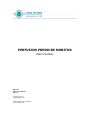
1
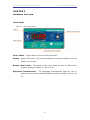
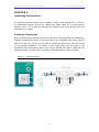
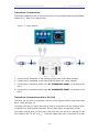
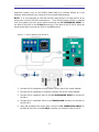
PERFUSION PRESSURE MONITOR
USER’S MANUAL
DOC-237
PM-4 User’s Manual
Rev. 1.1
Copyright © 2011
All Rights Reserved
Living Systems Instrumentation
www.livingsys.com
LIVING SYSTEMS INSTRUMENTATION
PM-4 PRESSURE MONITOR
THIS PAGE INTENTIONALLY LEFT BLANK
- ii -
LIVING SYSTEMS INSTRUMENTATION
PM-4 PRESSURE MONITOR
TABLE OF CONTENTS
Chapter 1 .............................................................................................. 1 Introduction ...................................................................................................... 1 System Components ........................................................................................ 1 Definition of Terms ......................................................................................... 1 Chapter 2 .............................................................................................. 2 Hardware Overview ............................................................................................ 2 Front Panel .................................................................................................... 2 Rear Panel ..................................................................................................... 3 Chapter 3 .............................................................................................. 4 Transducer Calibration ........................................................................................ 4 Chapter 4 .............................................................................................. 7 Operating Instructions ........................................................................................ 7 Plumbing Connections ...................................................................................... 7 Transducer Connections ................................................................................... 8 Transducer Connections with a PS-200 ............................................................... 8 Chapter 5 ............................................................................................ 10 Notes and Tips ................................................................................................ 10 Pressure Transducers .................................................................................... 10 Specifications ............................................................................................... 10 Living Systems Contact Information ................................................................. 11 - iii -
LIVING SYSTEMS INSTRUMENTATION
PM-4 PRESSURE MONITOR
CHAPTER 1
Introduction
The PM-4 Perfusion Pressure Monitor is designed to monitor and record two physiological
pressures in the range of 0 to 200 mmHg, as well as their difference, and their average.
It is ideally suited for studies of isolated vessels that are cannulated and perfused; for
example using Living System's Vessel Chambers where one transducer is located proximal
to the vessel and the other distal. Using this configuration, the differential pressure is a
measure of the perfusion pressure, giving rise to flow, or as a consequence of imposed
flow.
Also, the average pressure represents the mean vessel pressure when the flow
resistances of the two cannulae are similar. Changes in the caliber of the vessel during a
perfusion experiment will usually result in an alteration of the pressures.
The transducers may also be located in different branches of an isolated perfused
vascular bed, or organ, to provide pressure information, or to measure pressures at two
transducer locations in the absence of flow.
System Components
•
PM-4 Pressure Monitor
•
Two flow-thru solid state pressure transducers with extension cables for connection
to the PM-4.
•
Four BNC-BNC shielded cables for recording the pressures:
P1, P2, dP (i.e., (P1-P2)), and P AV (i.e., (P1+P2)/2)).
•
Power Cord (117 VAC or 230 VAC).
Definition of Terms
P1: The pressure as sensed by pressure transducer P1.
P2: The pressure as sensed by pressure transducer P2.
dP: The differential pressure, or the difference between P1 and P2.
P AV : The (mean) average pressure of P1 and P2.
-1-
LIVING SYSTEMS INSTRUMENTATION
PM-4 PRESSURE MONITOR
CHAPTER 2
Hardware Overview
Front Panel
Figure 2-1 – PM-4 Front Panel
Power Switch: Toggle switch to turn the PM-4 ON and OFF.
Display: Displays the value of the pressure reading that has been selected using the
Display Control Knob.
Display Control Knob:
The display control knob allows the user to select which
pressure reading to display; P AV , dP, P2 or P1.
Adjustment Potentiometers:
The adjustment potentiometers allow the user to
adjust the zero pressure reading (ZERO) and calibrate (SCALE) both P1 and
P2.
-2-
LIVING SYSTEMS INSTRUMENTATION
PM-4 PRESSURE MONITOR
Rear Panel
Figure 2-2 - PM-4 Back Panel
Outputs:
Four BNC analog output voltage jacks (BNC) provide 10mV/mmHg signals
for simultaneous recordings of P1, P2, dP and P AV .
Transducer Inputs: P1 and P2 refer to the telephone style jacks for the pressure
transducers
A/C Power: Connector for the line cord.
-3-
LIVING SYSTEMS INSTRUMENTATION
PM-4 PRESSURE MONITOR
CHAPTER 3
Transducer Calibration
It is important to note that changes in the temperature of the transducer will affect the
calibration. If this is critical, the following calibration procedure should be performed
with a heating lamp, which will raise the temperature of the transducers to approximately
that of the warm solution that flows through the transducers during a procedure.
Figure 3-1 - Transducer Calibration Hardware Configuration
Connect the hardware as shown above, in Figure 3-1.
1. Connect the P1 transducer cable to the P1 jack on the back of the PM-4.
2. Connect the P2 transducer cable to the P2 jack on the back of the PM-4.
3. Set the Display Control Knob on the front of the PM-4 to P1.
4. Open the stopcocks to air and release all pressure in the manometer so that it reads
0.00.
5. The Display on the front of the PM-4 should read 0.0. If it doesn’t, adjust the P1
Zero Adjustment Potentiometer until the reading is 0.0.
6. Set the Display Control Knob on the front of the PM-4 to P2.
7. The Display on the front of the PM-4 should read 0.0. If it doesn’t, adjust the P2
Zero Adjustment Potentiometer until the reading is 0.0.
-4-
LIVING SYSTEMS INSTRUMENTATION
PM-4 PRESSURE MONITOR
8. Close the stopcock on the distal side of the P2 transducer and increase the
manometer pressure to a steady reading slightly less than 200 mmHg, as shown
below.
Figure 3-2 - P2 Proximal Stopcock Closed with Slightly Less Than 200 mmHg in System
9. Adjust the P2 Scale Adjustment Potentiometer so that the Display on the PM-4
matches the manometer pressure value. For example, if the manometer reads 198,
then the digital display should also read 198. Also, the voltage at the Transducer
Output P2 connector, which can be read with a multimeter, will be 1.98 V.
10. Set the Display Control Knob on the front of the PM-4 to P1.
11. Adjust the P1 Scale Adjustment Potentiometer so that the Display on the PM-4
matches the manometer pressure value. For example, if the manometer reads 198,
then the digital display should also read 198. Also, the voltage at the Transducer
Output P1 connector, which can be read with a multimeter, will be 1.98 V.
12. Repeat steps 3 through 11 to ensure that the settings are accurate.
-5-
LIVING SYSTEMS INSTRUMENTATION
PM-4 PRESSURE MONITOR
13. Close the two-way stopcock separating the two transducers and open the stopcock on
the distal end of the P2 transducer, as shown below.
Figure 3-3 – Verifying the Reading of dP
14. Set the Display Control Knob on the front of the PM-4 to dP. The reading should be
the same as P1.
15. Set the Display Control Knob on the front of the PM-4 to P AV .
16. P AV is (P1+P2)/2. In this case, P2 is zero. Therefore, P AV is half of P1 ((P1+0)/2).
WARNING : If the PM-4 is being used in conjunction with the Pressure Servo (Model
PS-200) unit and only one P2 transducer is being used (after plugging the double
ended telephone cable into the lower port of the PS-200 and into the P2 port on the
PM-4), it is very important that they be calibrated together and both units be left in the
power ON position. If you wish to use the PS-200 subsequently without the PM-4, be
sure that the double ended telephone type cable is disconnected from the back of the
PS-200 before turning the PM-4 off.
-6-
LIVING SYSTEMS INSTRUMENTATION
PM-4 PRESSURE MONITOR
CHAPTER 4
Operating Instructions
It is important that the reading of P1 be greater or equal to the reading of P2 in order for
the differential pressure, dP (P1-P2) reading and output signal be a correct positive
pressure value. This is done by creating flow conditions from the proximal end to the
distal end of the vessel.
Plumbing Connections
When proximal pressure to the vessel inflow cannula is being controlled and measured, a
common arrangement is shown in the figure below. It is suggested that tubing (Tygon®
R3603 (2.4 mm O.D., 0.8 mm I.D.) be used to connect the distal end of the pump tubing
to the pressure transducer. The lengths of the tubing going from the pump to the
transducer and inflow cannula may be as long as desired, but keep in mind that the
longer the length, the more time it will take for perfused drugs to reach the vessel.
Figure 4-1 - Plumbing Diagram
-7-
LIVING SYSTEMS INSTRUMENTATION
PM-4 PRESSURE MONITOR
Transducer Connections
The following describes how to use the PM-4 with a Living Systems single vessel chamber
(Model CH-1). Refer to the figure below.
Figure 4-2 – Wiring Diagram
1. Connect the P1 transducer to the proximal (inflow) side of the vessel chamber.
2. Connect the P2 transducer to the distal (outflow) side of the vessel chamber.
3. Connect the P1 transducer cable to the P1 TRANSDUCER INPUT on the back of the
PM-4.
4. Connect the P2 transducer cable to the P2 TRANSDUCER INPUT on the back of the
PM-4.
Transducer Connections with a PS-200
The PM-4 can be used in conjunction with the Living System PS-200 Pump and Pump
Servo. Refer to Figure 4-3.
The signal from the P AV output jack may be used in conjunction with the Pressure Servo
to maintain the vessel pressure constant. Be sure both pieces of equipment are ON.
The Display Control Knob on the front of the PM-4 may now be set to read any of the
four pressures (P1, P2, dP, or P AV ). Each BNC output jack can be connected to a data
-8-
LIVING SYSTEMS INSTRUMENTATION
PM-4 PRESSURE MONITOR
acquisition system, such as the DATAQ (Model DAQ-L-U) interface offered by Living
Systems, which allows all four pressures to be recorded simultaneously.
NOTE: It is very important to note that the PM-4 must be left in the ON position at all
times when using the PS-200 Pressure Servo. If the PS-200 Pressure Servo is removed
from this system, the silver phone cable connecting the P2 TRANSDUCER INPUT on
the back of the PM-4 to the TO PM/4 connector on the back of the PS-200-S should be
disconnected before turning the PM-4 to the OFF position.
Figure 4-3 - Wiring Diagram with PS-200-S
1. Connect the P1 transducer to the proximal (inflow) side of the vessel chamber.
2. Connect the P2 transducer to the distal (outflow) side of the vessel chamber.
3. Connect the P1 transducer cable to the P1 TRANSDUCER INPUT on the back of
the PM-4.
4. Connect the P2 transducer cable to the TRANSDUCER connector on the back of
the PS-200-S.
5. Using the provided silver phone cable, connect the P2 TRANSDUCER INPUT on
the back of the PM-4 to the TO PM/4 connector on the back of the PS-200-S.
-9-
LIVING SYSTEMS INSTRUMENTATION
PM-4 PRESSURE MONITOR
CHAPTER 5
Notes and Tips
Pressure Transducers
-
Although the pressure transducers are closely matched, they are not
interchangeable. If a new or different pressure transducers is used, re-calibration of
the system is required. Follow the instructions in Chapter 3 to calibrate the
transducers.
-
In addition to physical damage (dropping, etc.), pressure transducers can be
damaged by excessive pressures (above 5000 mmHg). As a result, the pressure
readings may not be correct and erroneous readings will be observed.
-
In some situations, a broken transducer may have solution dripping or spraying
from the tiny air pressure equilibration hole in the center of the flat cable about 22
cm. from the transducer.
-
WARNING: Pressure transducers should never be immersed in liquid.
cause severe damage.
-
In rare situations, it has been observed that the pressure transducer is susceptible to
ambient radio frequency interference, such as signals from cordless telephone
transmitters. These erroneous signals can produce small, random pressure jumps. If
this problem is occurring, it is advisable to wrap the transducer in aluminum foil and
connect the foil to ground with a wire lead and clip.
-
The PM-4 must be grounded and connected to a three-pin power source. It is not
meant for use in environments where explosions may occur.
This may
Specifications
PM-4 Pressure Monitor
Power
100-120 VAC / 60 Hz
200-240 VAC / 50 Hz
Range
Pressure range 0–200 mmHg
0.1 mmHg resolution; ± 1% linearity; 3 samples/s
Analog Signal Outputs
10 mV/mmHg
<15 ms response time; ± 1% linearity
Weight
0.3 kg / 0.66 lbs
Size (W x H x D)
14.5 cm x 6.5 cm x 17.5 cm
5.7” x 2.56” x 6.89”
- 10 -
LIVING SYSTEMS INSTRUMENTATION
PM-4 PRESSURE MONITOR
PT-F Pressure Transducer
Pressure Range
-50 – 300 mmHg
Cable Length
48”
Inflow/Outflow ports
Male Luer with one 1-way stopcock
Living Systems Contact Information
Please contact us with any questions, or if hardware issues occur. Please find all contact
information at www.livingsys.com.
- 11 -