1
ST7 SOFTWARE LIBRARY
USER MANUAL
November 2005
Ref: DOC-ST7SOFT-LIB
USE IN LIFE SUPPORT DEVICES OR SYSTEMS MUST BE EXPRESSLY AUTHORIZED.
STMicroelectronics PRODUCTS ARE NOT AUTHORIZED FOR USE AS CRITICAL COMPONENTS IN
LIFE SUPPORT DEVICES OR SYSTEMS WITHOUT THE EXPRESS WRITTEN APPROVAL OF STMicroelectronics. As used herein:
1.Life support devices or systems are those which
(a) are intended for surgical implant into the body,
or (b) support or sustain life, and whose failure to
perform, when properly used in accordance with
instructions for use provided with the product, can
be reasonably expected to result in significant injury to the user.
1
2. A critical component is any component of a life
support device or system whose failure to perform
can reasonably be expected to cause the failure
of the life support device or system, or to affect its
safety or effectiveness.
USER MANUAL
ST7 FAMILY
ST7 SOFTWARE LIBRARY
1 INTRODUCTION
This document describes the features, the files structure, examples, module drivers and
guidelines for using the ST7 software library package.
1.1 ABBREVIATIONS USED
• SCI
Serial Communication Interface
• ADC
Analog to Digital Converter
• SPI
Serial peripheral Interface
• I2C
Inter Integrated Circuit
• CAN
Controller Area Network
• WDG
Watchdog
• EEPROM
Electrically Erasable Prog. Read Only Memory
• ITC
Interrupt Controller
• I/O
Input/Output Ports
• PWM
Pulse Width Modulation
• ART
Auto Reload Timer
• TBU
Time Base Unit
• TIMER
16-bit Timer
• TIMER8
8-bit Timer
• LT
Lite Timer
• LART
Lite Auto Reload Timer
• STVD7
ST Visual Debug 7
• MCD
Microcontroller Division
1.2 NAMING CONVENTIONS
Periph. All names starting with Periph are referring to the name of the peripheral.
Rev. 4.0
November 2005
Table of Contents
1 INTRODUCTION . . . . . . . . . . . . . . . . . . . . . . . . . . . . . . . . . . . . . . . . . . . . . . . . . . . . . . 3
1.1 ABBREVIATIONS USED . . . . . . . . . . . . . . . . . . . . . . . . . . . . . . . . . . . . . . . . . . . 3
1.2 NAMING CONVENTIONS . . . . . . . . . . . . . . . . . . . . . . . . . . . . . . . . . . . . . . . . . . 3
2 OVERVIEW . . . . . . . . . . . . . . . . . . . . . . . . . . . . . . . . . . . . . . . . . . . . . . . . . . . . . . . . . . 7
2.1 FUNCTIONAL SCOPE . . . . . . . . . . . . . . . . . . . . . . . . . . . . . . . . . . . . . . . . . . . . . 7
2.2 FEATURES . . . . . . . . . . . . . . . . . . . . . . . . . . . . . . . . . . . . . . . . . . . . . . . . . . . . . . 7
3 GETTING STARTED WITH TOOLS . . . . . . . . . . . . . . . . . . . . . . . . . . . . . . . . . . . . . . . 8
3.1 SOFTWARE TOOLS . . . . . . . . . . . . . . . . . . . . . . . . . . . . . . . . . . . . . . . . . . . . . . 8
3.2 HARDWARE TOOLS . . . . . . . . . . . . . . . . . . . . . . . . . . . . . . . . . . . . . . . . . . . . . . 8
3.3 TECHNICAL LITERATURE . . . . . . . . . . . . . . . . . . . . . . . . . . . . . . . . . . . . . . . . . 8
3.4 HOW TO INSTALL THE LIBRARY . . . . . . . . . . . . . . . . . . . . . . . . . . . . . . . . . . . 9
4 LIBRARY STRUCTURE . . . . . . . . . . . . . . . . . . . . . . . . . . . . . . . . . . . . . . . . . . . . . . . 10
4.1 ST7_LIBX . . . . . . . . . . . . . . . . . . . . . . . . . . . . . . . . . . . . . . . . . . . . . . . . . . . . . . 10
4.2 ST7LIB_CONFIG.H . . . . . . . . . . . . . . . . . . . . . . . . . . . . . . . . . . . . . . . . . . . . . . 10
4.2.1
4.2.2
User part of the ST7lib_config.h . . . . . . . . . . . . . . . . . . . . . . . . . . . . . . 11
Non-User part of the ST7lib_config.h . . . . . . . . . . . . . . . . . . . . . . . . . . 11
4.3 PERIPHERALS LIBRARY . . . . . . . . . . . . . . . . . . . . . . . . . . . . . . . . . . . . . . . . . 11
4.3.1
4.3.2
Peripherals directory . . . . . . . . . . . . . . . . . . . . . . . . . . . . . . . . . . . . . . . 11
Periph directory . . . . . . . . . . . . . . . . . . . . . . . . . . . . . . . . . . . . . . . . . . . 11
4.3.2.1 C directory . . . . . . . . . . . . . . . . . . . . . . . . . . . . . . . . . . . . . . . . . . 12
4.4 DEVICES . . . . . . . . . . . . . . . . . . . . . . . . . . . . . . . . . . . . . . . . . . . . . . . . . . . . . . 12
4.5 DOCUMENTATION . . . . . . . . . . . . . . . . . . . . . . . . . . . . . . . . . . . . . . . . . . . . . . 13
4.6 DEMO . . . . . . . . . . . . . . . . . . . . . . . . . . . . . . . . . . . . . . . . . . . . . . . . . . . . . . . . . 13
5 EXAMPLE . . . . . . . . . . . . . . . . . . . . . . . . . . . . . . . . . . . . . . . . . . . . . . . . . . . . . . . . . . 14
5.1 SOURCES FOLDER . . . . . . . . . . . . . . . . . . . . . . . . . . . . . . . . . . . . . . . . . . . . . 14
5.2 WORKSPACE . . . . . . . . . . . . . . . . . . . . . . . . . . . . . . . . . . . . . . . . . . . . . . .235
. . . 15
5.2.1
4/235
1
STVD7_2x . . . . . . . . . . . . . . . . . . . . . . . . . . . . . . . . . . . . . . . . . . . . . . . 15
Table of Contents
5.2.2
5.2.3
STVD7_3x . . . . . . . . . . . . . . . . . . . . . . . . . . . . . . . . . . . . . . . . . . . . . . . 15
winIDEA (only for ST72F561 and CAN peripheral) . . . . . . . . . . . . . . . . 15
6 HOW TO USE THE LIBRARY . . . . . . . . . . . . . . . . . . . . . . . . . . . . . . . . . . . . . . . . . . 16
6.1 STANDARD PROCEDURE FOR ALL PERIPHERALS . . . . . . . . . . . . . . . . . . . 16
6.2 USING THE COMMUNICATION PERIPHERALS LIBRARY . . . . . . . . . . . . . . 17
6.2.1
6.2.2
6.2.3
6.2.4
SCI . . . . . . . . . . . . . . . . . . . . . . . . . . . . . . . . . . . . . . . . . . . . . . . . . . . . 17
SPI . . . . . . . . . . . . . . . . . . . . . . . . . . . . . . . . . . . . . . . . . . . . . . . . . . . . . 18
I2C . . . . . . . . . . . . . . . . . . . . . . . . . . . . . . . . . . . . . . . . . . . . . . . . . . . . . 19
CAN . . . . . . . . . . . . . . . . . . . . . . . . . . . . . . . . . . . . . . . . . . . . . . . . . . . . 21
6.2.4.1 DESCRIPTION . . . . . . . . . . . . . . . . . . . . . . . . . . . . . . . . . . . . . . 22
6.2.4.2 DATA STRUCTURES . . . . . . . . . . . . . . . . . . . . . . . . . . . . . . . . . 22
6.2.4.3 DATA TYPES . . . . . . . . . . . . . . . . . . . . . . . . . . . . . . . . . . . . . . . 23
6.2.4.4 MEMORY USAGE . . . . . . . . . . . . . . . . . . . . . . . . . . . . . . . . . . . 23
6.2.4.5 PARAMETER CONFIGURATION . . . . . . . . . . . . . . . . . . . . . . . . 23
6.2.4.6 Tx & Rx BUFFER USAGE . . . . . . . . . . . . . . . . . . . . . . . . . . . . . 25
6.2.4.7 IMPLEMENTATION HINTS . . . . . . . . . . . . . . . . . . . . . . . . . . . . 25
6.3 OTHER PERIPHERALS . . . . . . . . . . . . . . . . . . . . . . . . . . . . . . . . . . . . . . . . . . . 26
6.3.1
6.3.2
TIMER . . . . . . . . . . . . . . . . . . . . . . . . . . . . . . . . . . . . . . . . . . . . . . . . . . 26
I/O . . . . . . . . . . . . . . . . . . . . . . . . . . . . . . . . . . . . . . . . . . . . . . . . . . . . . 26
6.4 MEMORY MODELS . . . . . . . . . . . . . . . . . . . . . . . . . . . . . . . . . . . . . . . . . . . . . . 26
6.5 PORTING APPLICATIONS FROM LIBRARY VERSION 1.0 . . . . . . . . . . . . . . 26
7 PRESENTATION OF LIBRARY FUNCTIONS . . . . . . . . . . . . . . . . . . . . . . . . . . . . . . 27
7.1 LIBRARY REFERENCES . . . . . . . . . . . . . . . . . . . . . . . . . . . . . . . . . . . . . . . . . 27
8 RELEASE INFORMATION . . . . . . . . . . . . . . . . . . . . . . . . . . . . . . . . . . . . . . . . . . . . . 28
8.1 PERIPHERALS . . . . . . . . . . . . . . . . . . . . . . . . . . . . . . . . . . . . . . . . . . . . . . . . . 28
8.2 DEVICES . . . . . . . . . . . . . . . . . . . . . . . . . . . . . . . . . . . . . . . . . . . . . . . . . . . . . . 29
9 FUNCTION DESCRIPTIONS . . . . . . . . . . . . . . . . . . . . . . . . . . . . . . . . . . . . . . . . . . . 30
9.1 GENERAL PURPOSE PERIPHERALS . . . . . . . . . . . . . . . . . . . . . . . . . . . . . . . 30
9.1.1
9.1.2
9.1.3
9.1.4
9.1.5
5/235
ADC . . . . . . . . . . . . . . . . . . . . . . . . . . . . . . . . . . . . . . . . . . . . . . . . . . . . 30
SCI . . . . . . . . . . . . . . . . . . . . . . . . . . . . . . . . . . . . . . . . . . . . . . . . . . . . 34
SPI . . . . . . . . . . . . . . . . . . . . . . . . . . . . . . . . . . . . . . . . . . . . . . . . . . . . . 59
I2C MASTER . . . . . . . . . . . . . . . . . . . . . . . . . . . . . . . . . . . . . . . . . .235
. . . 81
I2C SLAVE . . . . . . . . . . . . . . . . . . . . . . . . . . . . . . . . . . . . . . . . . . . . . 107
Table of Contents
9.1.6
9.1.7
9.1.8
9.1.9
9.1.10
9.1.11
9.1.12
9.1.13
9.1.14
9.1.15
9.1.16
16-bit TIMER (TIMER) . . . . . . . . . . . . . . . . . . . . . . . . . . . . . . . . . . . . . 124
8-bit TIMER (TIMER8) . . . . . . . . . . . . . . . . . . . . . . . . . . . . . . . . . . . . . 137
LITE TIMER (LT) . . . . . . . . . . . . . . . . . . . . . . . . . . . . . . . . . . . . . . . . . 150
PWMART . . . . . . . . . . . . . . . . . . . . . . . . . . . . . . . . . . . . . . . . . . . . . . 159
LITE AUTO-RELOAD TIMER (LART) . . . . . . . . . . . . . . . . . . . . . . . . . 171
TBU . . . . . . . . . . . . . . . . . . . . . . . . . . . . . . . . . . . . . . . . . . . . . . . . . . . 187
WDG . . . . . . . . . . . . . . . . . . . . . . . . . . . . . . . . . . . . . . . . . . . . . . . . . . 192
ITC . . . . . . . . . . . . . . . . . . . . . . . . . . . . . . . . . . . . . . . . . . . . . . . . . . . . 196
MCC . . . . . . . . . . . . . . . . . . . . . . . . . . . . . . . . . . . . . . . . . . . . . . . . . . 208
EEPROM . . . . . . . . . . . . . . . . . . . . . . . . . . . . . . . . . . . . . . . . . . . . . . . 214
I/O . . . . . . . . . . . . . . . . . . . . . . . . . . . . . . . . . . . . . . . . . . . . . . . . . . . . 219
9.2 APPLICATION SPECIFIC PERIPHERALS . . . . . . . . . . . . . . . . . . . . . . . . . . . 227
9.2.1
CAN LIBRARY FUNCTION LIST . . . . . . . . . . . . . . . . . . . . . . . . . . . . 227
9.2.1.1 Initialization-Services . . . . . . . . . . . . . . . . . . . . . . . . . . . . . . . . 227
9.2.1.2 Transmit-Services . . . . . . . . . . . . . . . . . . . . . . . . . . . . . . . . . . . 228
9.2.1.3 Sleep/Wakeup Services . . . . . . . . . . . . . . . . . . . . . . . . . . . . . . 230
9.2.1.4 Status Information Service . . . . . . . . . . . . . . . . . . . . . . . . . . . . 231
9.2.1.5 Transmit/Receive Task Services . . . . . . . . . . . . . . . . . . . . . . . . 231
9.2.1.6 Interrupt Services . . . . . . . . . . . . . . . . . . . . . . . . . . . . . . . . . . . 232
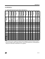
10 APPENDIX A . . . . . . . . . . . . . . . . . . . . . . . . . . . . . . . . . . . . . . . . . . . . . . . . . . . . . 233
10.1SUPPORTED DEVICES AND THEIR PERIPHERALS . . . . . . . . . . . . . . . . . . 233
11 REVISION HISTORY . . . . . . . . . . . . . . . . . . . . . . . . . . . . . . . . . . . . . . . . . . . . . . . 234
235
6/235
Overview
2 OVERVIEW
2.1 FUNCTIONAL SCOPE
ST7 library is a software package consisting of device drivers for all standard ST7 peripherals.
Each device driver has a set of functions covering the functionality of the peripheral. The
source code, developed in ‘C’ is fully documented and thoroughly tested.
This library has been developed to make it easy for you to develop ST7 applications. A basic
knowledge of C programming is required. With ST7 library, you can use any ST7 device in
your application without having to study each peripheral specification in-depth. As a result,
using this library can save you a lot of coding time and save part of the cost of developing and
integrating your application.
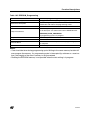
2.2 FEATURES
– NEW: Supports new devices ST72325 and ST7232A
– NEW: Provided workspace for both STVD7 version 3.x and 2.x
– The ST7 library package consists of device driver library files, the configuration and setup
files.
– With each peripheral, application example code is provided. This is an application tailored to
a specific ST7 device, which uses the library functions to drive the peripheral. You can use
it without modification in an ST development kit.
– A detailed function reference is provided for each peripheral
– The functional behaviour and input/output parameters of each function are described in detail in the user manual
– The functions are coded in ’C’ and are compatible with Metrowerks & Cosmic compilers
– The ST7 library is MISRA compliant
– Registry Key is added to provide information on installation path and version
7/235
Getting Started with Tools
3 GETTING STARTED WITH TOOLS
3.1 SOFTWARE TOOLS
The library functions have been debugged with the ST7 software toolset. The ST7 software
toolset can be found on the MCU CD-ROM or can be downloaded from the ST website:
http://www.st.com/mcu
The following versions of the C compilers are used:
– METROWERKS C toolchain version 4.2.5
– COSMIC C toolchain version 4.4d
A valid license has to be purchased for Metrowerks and Cosmic compilers. Free versions with
code limitations may also be available, check the websites of the two providers for further information.
Note: Since Metrowerks was previously known as Hiware, both C compilers are compatible.
3.2 HARDWARE TOOLS
Hardware tools are not required for using the library, you can use the STVD7 simulator if it
supports the target device (check with the latest device documentation). However you can use
the following Hardware tools for development support:
– ICD based debugging tools (like InDart from Softec or R-Link ST from Raisonance)
– ST Emulators (EMU or DVP)
– ST7232x - SK/ RAIS (Starter Kit by Raisonance)
– ST evaluation boards / starter kits (for example ST7232x-EVAL)
– ST7-STICK - ST in-circuit communication kits
– ICC socket boards - these complement any tool that has ICC programming capabilities
(like ST7-STICK, InDART, R-Link, DVP, EMU, etc.)
– Third party emulators (from Hitex or iSYSTEM)
– Engineering Programming Board (EPB) or Gang Programmer
3.3 TECHNICAL LITERATURE
As well as reading the ST7 device datasheet, you should also read the following documents
before using the library. All the documents and the device datasheets are available on the ST
website and on the MCU CD ROM.
ST7 Software library user manual
Application note: AN978: Key features of the STVD7 ST7 Visual debug package
Application note: AN989: Getting started with the ST7 Hiware C Toolchain
Application note: AN983: Key features of the Cosmic ST7 C- Compiler package
Application note: AN1064: Writing Optimized Hiware C Language for ST7
Application note: AN1938: Visual Develop for ST7 Cosmic C Toolset Users
Application note: AN1939: Visual Develop for ST7 Metrowerks C Toolset Users
8/235
1
Getting Started with Tools
3.4 HOW TO INSTALL THE LIBRARY
The library is supplied in a zip package. Extraction of this zip file will give the setup file
ST7LibxSetup.exe, where x represents the latest numeric version of the library. Click on the
setup file to install the library on the host system.
9/235
Library Structure
4 LIBRARY STRUCTURE
4.1 ST7_LIBX
Location:
\Root directory
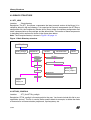
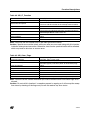
Description: The ST7_libx (where x represents the latest numeric version of the library) is installed by default in the root directory. It is comprised of five main components: the ST7library
configuration file, the Peripherals (Device driver) library folder, the devices configuration files
folder, documentation on the package and the demo folder. The location of these components
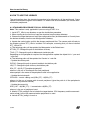
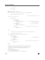
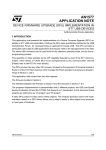
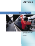
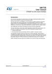
is described in this section and shown in the figure given below.
Note: The Example directory is shown in Figure 2 on page 14.
Figure 1. Main Directory structure
ST7_LIBx
ST7lib_config.h
Peripherals
Devices
Documentation
Demo
Device 1
Periph 1
Periph 2
Device n
Periph14
device_reg.h
device_reg.c
device_periph.h
C Folder
Metrowerks
Example
Cosmic
periph.c
periph.h
periph_hr.h
4.2 ST7LIB_CONFIG.H
Location:
ST7_libx\ST7lib_config.h
Description: ST7lib_config.h is the entry point for the user. You have to include this file in your
application (main.c). This file is used to define specific labels for example, to define the mode
of transmission of communication peripherals, cpu frequency, etc.
10/235
Library Structure
St7lib_config.h is divided into two major sections:
4.2.1 User part of the ST7lib_config.h
– You can customize this portion to your application requirement
– You can define your own labels and macros here
– You can change the CPU clock value (default is 8MHz)
– For the ST72F264 device you can select whether to use Port C as ei0 or ei1
– The target ST7 device file (st72xxx_periph.h) has to be included in this file
Note: An error message “No Valid ST7 MCU Configuration” will be generated by the compiler
if no device file has been included.
4.2.2 Non-User part of the ST7lib_config.h
This part contains the labels for METROWERKS and COSMIC compilers. It contains the compiler definitions as follows:
#if (defined __HIWARE__ | defined __MWERKS__ )
#define _HIWARE_
#else
#ifdef __CSMC__
#define _COSMIC_
#else #error “Unsupported Compiler!”
#endif
#endif
/* Compiler defines not found */
The labels __MWERKS__ (__HIWARE__) and __CSMC__ are automatically set by the
Metrowerks and cosmic compilers respectively. If none of these two compilers are selected
then an error message “Unsupported Compiler!” appears on the debugger window.
Macros definitions in ST7lib_config.h:
ST7lib_Config.h file also contains a list of macros. They are as follows.
1. EnableInterrupts: You can use this macro to reset the interrupt mask, this macro is equivalent to the RIM instruction in assembly.
2. Nop: No operation. This is equivalent to the nop instruction in assembly
3. DisableInterrupts: You can use this macro to set the interrupt mask, this macro is equivalent
to the SIM instruction in assembly.
4. WaitforInterrupt: This is equivalent to the “wfi” instruction in assembly.
4.3 PERIPHERALS LIBRARY
4.3.1 Peripherals directory
Location:
ST7_libx\Peripherals
Description: This directory contains subdirectories by the name of the peripheral.
Subdirectory names: ADC, EEPROM, I2C, I2CSlave, IO, ITC, LART, LT, MCC, PWMART,
SCI, SPI, TBU, TIMER, TIMER8, WDG, CAN.
4.3.2 Periph directory
Location:
ST7_libx\Peripherals\Periph\sources
11/235
Library Structure
Description: Each subdirectory contains a ‘C’ sub folder which contains peripheral library files.
4.3.2.1 C directory
Location:
ST7_libx\Peripherals\Periph\sources\C
Description: Each subdirectory contains the source files, header files and an example folder
showing the usage of the functions.
Files: Periph.c, Periph.h, Periph_hr.h
Periph.c
Inclusion of periph_hr.h, periph.h, ST7lib_config.h. It contains the Peripheral functions with
some conditional compilation options.
Periph.h:
This contains the (typedef enum) parameters for each peripheral, prototypes of functions defined in Peripheral.c and definition of Peripheral constant definitions.
Periph_hr.h
This file contains the bit mapping of the hardware registers used for the peripherals.
4.4 DEVICES
Location:
ST7_LIBx\Devices
Description:
1. Contains the files which define all registers for each device and includes the file which
is used to select peripherals for the application. This register file is included in the
ST7lib_config.h.
The folder ST7_LIBx\Devices\ST7xx contains st7xx_reg.h, st7xx_reg.c and
st7xx_periph.h files.
st7xx_reg.h: This file contains a declaration of the register variables of st7xx for
Metrowerks and definitions of the register variables for the Cosmic compiler.
st7xx_reg.c: This file contains definitions of the register variables of st7xx device.
st7xx_periph.h: This file is used to select which peripherals of st7xx device are used in
the application.
2. Contains the generic configuration files both Metrowerks and Cosmic compilers.
Metrowerks: Contains the mapping file (ST72xxx.prm) for all the hardware registers in device, Make file (ST72xxx.mak) to build the application and the default.env which defines
all the useful paths and options for the application.
COSMIC: make file to build the application (ST72xxx.mak), link file (ST72xxx.lkf) used to
link the device and the interrupt mapping file (vector_xxx.c) for the target device.
Notes:
1. This software covers 13 main devices and their subsets. You have to include the file from
the main device section in order to support the related subsets.
2. The register files in the ST7 library are different from those provided with the STVD7 ver 3.x.
Take care to include the correct one.
12/235
Library Structure
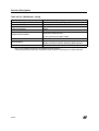
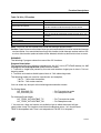
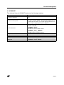
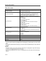
Table 1. Supported devices
Main device
Subsets
ST72F62
ST72F621, ST72F622, ST72F623, ST72F611
ST72F63B
ST72F63BK1, ST72F63BK2, ST72F63BK3
ST72F65
ST72F65
ST72F521
ST72F521, ST72F321,ST72F324
ST72325
ST72F325(C/J/K)4, ST72F325(AR/C/J/K)6/7/9
ST7232A
ST72F32AK2
ST7FLITE0
ST7FLITE05, ST7FLITE09
ST7FLITE1
ST7FLITE10, ST7FLITE15, ST7FLITE19, ST7FLITE1B
ST7FLITE2
ST7FLITE20, ST7FLITE25, ST7FLITE29
ST7FLITE3
ST7FLITE3
ST72F264
ST72F260G1, ST72F262G1, ST72F262G2,
ST72F264G1, ST72F264G2
ST72F561
ST72F561(R/J/K)9, ST72F561(R/J/K)6
ST7SUPERLITE
ST7FLITES2, ST7FLITES5
4.5 DOCUMENTATION
Location:
ST7_LIBx\Documentation
Description: This directory contains the global user manual describing each peripheral library
and its use in detail.
Files: user manual.pdf
4.6 DEMO
Location:
ST7_LIBx\DEMO
Description: This directory contains an application program which demonstrates the use of the
ST7LIB on the devices ST72F521, ST72F62, ST7FLITE0, ST7FLITE2, ST7SUPERLITE,
ST72F561 and ST72325. The program uses all the peripheral libraries together for a particular
application. The purpose of the demo is to help to develop an application using the software library.
13/235
Example
5 EXAMPLE
Location:
ST7_LIBx\Peripherals\Periph\sources\C\Example
Description: Contains the example application code for each peripheral individually. The code
has been developed using the peripheral library functions exercises the functionality of that
peripheral. The configuration and workspace has been provided for users of both STVD7
ver2.x and 3.x. The example has been compiled and tested using both Metrowerks and
Cosmic compilers and configuration files are provided.
Subdirectories: Sources, workspace
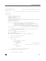
Figure 2. Example directory structure
Example
Sources
workspace
main.c
st7lib_config.h
st72xx_periph.h
STVD7_2x
Config
Cosmic
st72xxx.mak
st72xxx.lkf
vector_xxx.c
STVD7_3x
periph_mwerks.wsp
periph_csmc.wsp
Metrowerks
st72xxx.mak
st72xxx.prm
default.env
Object
Cosmic
periph .map
periph.elf
periph.o
main.o
periph_hr.0
periph.st7
vector_xxx.o
periph.s19
Metrowerks
Metrowerks
periph_mwerks.stw
periph_mweks.stp
interrupt_vector.c
vector.c
periph_csmc.stw
periph_csmc.stp
periph .map
periph.abs
periph.o
main.o
periph_hr.0
periph.s19
5.1 SOURCES FOLDER
Description: Contains the ST7lib_config.h, the main application file and the peripheral source
files needed to run the application
14/235
Example
5.2 WORKSPACE
This folder contains configuration and workspace files for both STVD7 ver2.x and 3.x as per
the directory structure shown in figure 2.
Note:
1. For ST72F561 demo and CAN peripheral, winIDEA workspace is also available.
2. For ST72325 and ST7232A demo STVD7_3X workspace is only available.
5.2.1 STVD7_2x
This folder contains relevant configuration files for ST7 Visual Debug ver 2.x. Subdirectories:
Config, Object
Config Folder: Contains the configuration files for both Metrowerks and Cosmic compilers.
metrowerks: Contains the mapping file (ST72xxx.prm) for all the hardware registers in the device, the Make file (ST72xxx.mak) for building the application and the default.env file which
defines all the useful paths names and options for the application.
COSMIC: Contains the make file for building the application (ST72xxx.mak), the link file
(ST72xxx.lkf) used to link the device and the interrupt mapping file (vector_xxx.c) for the target
device.
Object Folder:
These folders are used for temporary storage of object and executable files generated by the
compiler in respective directories - metrowerks and cosmic.
5.2.2 STVD7_3x
This folder contains relevant Cosmic and Metrowerks workspace for ST7 Visual Debug ver
3.X, as the configuration files are automatically generated.
5.2.3 winIDEA (only for ST72F561 and CAN peripheral)
This folder contains relevant configuration files for winIDEA.
Subdirectories: Config, Object
For details related to Subdirectories refer to Section 5.2.1
15/235
How to use the library
6 HOW TO USE THE LIBRARY
The next section gives the standard procedure to be followed for all the peripherals. Some
specific instructions are given in the section 7.2 which have to be followed if you use the communication peripherals.
6.1 STANDARD PROCEDURE FOR ALL PERIPHERALS
Note: This section is only applicable if you are using STVD7 v2.x.
1. Install ST7_LIBx in one directory as per the installation procedure.
2. When starting for the first time, copy the structure from the demo directory.
3. Choose the target device and copy the configuration files (for Metrowerks or Cosmic) from
the devices directory into the user configuration directory.
4. Update the useful paths and link the chosen peripherals files. The source path will refer to
the directory where ST7_LIBx is installed. For example, assuming that you have installed
ST7_LIBx in D:\
a) The following paths will be updated for Metrowerks in the Default.env:
ST7LIB_PT: Change this path to installation of library
TOOL_PT: Change this path to Metrowerks toolchain path
Depending on the peripherals required for the application update the object list in *.prm and
*.mak files.
b) The following paths will be updated for Cosmic in *.mak file
– Update the source path
PATHC: Change this path to cosmic toolchain installation path
LIB_PT: Change this path to library installation path
SRx_PT = $(LIB_PT)\peripherals\periph\C
where x is the no. of source path for each peripheral
where periph is the name of the peripheral used in the application
– Update the include path
CFLAGS = +mods +debug -co $(OBJ_PT) -i $(SRx_PT)
where x is the no. of source path for each peripheral (give the path of all the peripherals
present in the particular device)
– Update the source list
SRC_LIST = $(OBJ_PT)\..\..\source\main.c $(SRx_PT)
where x is the no. of peripheral used
5. Modify ST7lib_config.h file to include the target device, CPU frequency and the communication mode if any of the communication peripherals is used.
6. Include ST7lib_config.h in main.c
16/235
How to use the library
7. Write the application program using the library functions given in the user manual for each
peripheral and compile.
Caution: Only the ST7lib_config.h and the files contained in the configuration subdirectory of
the examples folder are user-modifiable, the rest of the source files are write protected.
Changing peripheral source files and header files may adversely affect the library operations
and this will be complicated to update when there are new library releases.
6.2 USING THE COMMUNICATION PERIPHERALS LIBRARY
6.2.1 SCI
This part of the user manual contains the detailed description of all the functions for the SCI.
An example ‘C’ program has been given at the end.
You can select either of the two Transmission/Reception modes of SCI implemented inside
the library. For selecting any of the possible modes described below you need to select the
corresponding #define statement inside the ST7lib_Config.h file
Polling:
With this mechanism the data can be transmitted or received by polling the status of the corresponding flag. Here both the single as well as continuous Transmission/Reception is possible. In continuous Transmission/Reception, control will be inside the function until all the requested data is Transmitted/Received and hence the application software has the risk of
losing control if there is a breakdown in communication (the SCI mode is disabled). To avoid
this risk, you can use the single byte transmission with some time out protection inside this
mechanism. This mechanism can only be used with the SCI in half duplex mode. To use this
mode you must have selected the following # define labels inside the ST7lib_config.h file:
SCI_POLLING_TX
-- For Transmission mode
SCI_POLLING_RX
-- For Reception mode
For SCI2 in ST72F561 device the labels are:
SCI2_POLLING_TX
-- For Transmission mode
SCI2_POLLING_RX
-- For Reception mode
Interrupt driven without communication buffer:
With this method data can be Transmitted/Received either in single or continuous mode using
interrupts. In continuous mode the user data is directly being read/written from/to the addresses passed by the user. After each byte of data transfer an interrupt is acknowledged and
the control goes to the interrupt subroutine. The main advantage of using interrupts rather
than polling is that control does not stay in the function till the last data is Transmitted/Received and hence the SCI can be used in full duplex mode. Here, you should take care not to
read/write the user buffer until the Transmission/Reception is complete. To use this mode you
must select the following # define labels in the ST7lib_config.h file:
SCI_ITDRV_WITHOUTBUF_TX
-- For Transmission
SCI_ITDRV_WITHOUTBUF_RX
-- For Reception
For SCI2 in ST72F561 device the labels are:
SCI2_ITDRV_WITHOUTBUF_TX
-- For Transmission on SCI2
SCI2_ITDRV_WITHOUTBUF_RX
-- For Reception on SCI2
17/235
How to use the library
6.2.2 SPI
SPI: This part of the user manual contains the detailed description of all the functions for the
SPI. An example C program has been given at the end.
The SPI can be used as Single master (multiple slaves) and multi master systems in full duplex mode. This can be configured by using parallel port pins to control the SS pin by software.
The transfer of master or slave control can be implemented using a handshake method
through the I/O ports or by an exchange of code messages through the serial peripheral interface system.
In order to respect the SPI protocol, you must define the configuration setting
SPI_SLAVE_CONFIG in ST7lib_config.h file as shown below, in order to be able to transmit
data in software slave mode. #define SPI_SLAVE_CONFIG To select any of the possible
communication modes described below you need to select the corresponding #define statement inside the ST7lib_config.h file. These modes are applicable for all communication peripherals (SPI, SCI and I2C).
Polling:
With this mechanism the data can be transmitted or received by polling the status of the corresponding flag. Both single and continuous Transmission/Reception is possible. In the case
of continuous Transmission/Reception the function keeps control until all the requested data is
Transmitted/Received and hence the application software has the risk of losing control if there
is a breakdown in communication (the SCI mode is disabled). To avoid the risk, you can use
the single byte transmission with some timeout protection inside this mechanism. This mechanism can only be used with the SPI in half duplex mode. To use this mode, you must have selected the following # define labels inside the ST7lib_config.h file:
SPI_POLLING_TX
-- For Transmission mode
SPI_POLLING_RX
-- For Reception mode
Interrupt driven without communication buffer:
Data can be Transmitted/Received both in single as well as continuous mode through the interrupt driven mechanism. In the continuous mode the user data is directly being read/written
from/to the addresses passed by the user. After each byte of data transfer an interrupt is acknowledged and the control goes to the interrupt subroutine. The main advantage of using interrupts rather than polling is that control does not stay in the function till the last data is Transmitted/Received and hence the SPI can be used in full duplex mode. Here you should take
care not to read/write the user buffer until the Transmission/Reception completion. To use this
mode you must select the following # define labels inside the ST7lib_config.h file:
SPI_ITDRV_WITHOUTBUF_TX
-- For Transmission
SPI_ITDRV_WITHOUTBUF_RX -- For Reception
Notes:
1. If both SPI_ ITDRV_WITHOUTBUF_TX and SPI_ITDRV_WITHOUTBUF_RX are defined
in full duplex mode, then the program will perform either transmission or reception (only transmission as per the present structure) since, the peripheral has a single interrupt for both
Transmission and Reception completion. Because of this correct full duplex communication
will be prevented. In order to operate the SPI in Full Duplex Mode, it is required that either the
18/235
How to use the library
Transmission or Reception is performed in Polling Mode and the other in Interrupt Driven
Mode. So, you can use any one of the following combinations in full duplex mode.
SPI_POLLING_TX
-- For Transmission mode
SPI_ITDRV_WITHOUTBUF_RX -- For Reception
(or)
SPI_ITDRV_WITHOUTBUF_TX
-- For Transmission
SPI_POLLING_RX
-- For Reception mode
6.2.3 I2C
This part of the user manual contains the detailed description of all the functions for I2C. An
example C program has been given at the end. You can select either of the two Transmission/
Reception modes implemented in the library. To select any of the possible modes described
below, you need to select the corresponding #define statement inside the ST7lib_config.h file.
Polling:
With this mechanism the data can be transmitted or received by polling the status of the corresponding flag. Either single or continuous Transmission/Reception is possible. In continuous Transmission/Reception control stays inside the function until all the requested data is
Transmitted/Received and hence the application software risks losing control if there is a
breakdown in communication (if the I2C mode is disabled). To avoid the risk, the appplication
can use single byte transmission with some timeout protection. This mechanism can only be
used with the I2C in half duplex mode. To use this mode, you must have selected the following
# define labels in the ST7lib_config.h file:
I2C_POLLING_TX
-- For Transmission mode
I2C_POLLING_RX
-- For Reception mode
Interrupt driven without communication buffer
Data can be Transmitted/Received both in single as well as continuous mode through the interrupt driven mechanism. In continuous mode the user data is directly read/written from/to the
addresses passed by the user. After each byte of data transfer an interrupt is acknowledged
and the control goes to the interrupt subroutine. The advantage of using interrupts rather than
polling is that control does not stay in the function till the last data is Transmitted/Received.
Here, care should be taken not to read/write the user-buffer until the Transmission/Reception
completes. To use this mode, you must select the following # define labels inside the
ST7lib_config.h file:
I2C_ITDRV_WITHOUTBUF_TX
-- For Transmission
I2C_ITDRV_WITHOUTBUF_RX -- For Reception
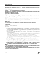
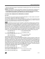
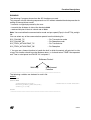
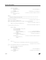
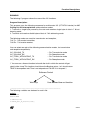
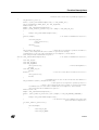
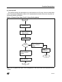
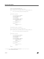
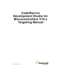
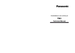
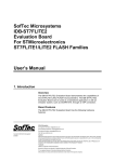
Master Receiver Communication Methodology:
In Master receiver mode, to close the communication the STOP bit must be set to generate a
stop condition, before reading the last byte from the DR register. In order to generate the nonacknowledge pulse after the last received data, the ACK bit must be cleared just before
reading the second last byte. The following flowchart shows the management of the ACK and
STOP bits, when the master is receiving.
19/235
How to use the library
For Example, if ‘N’ Bytes to be received,
:
:
:
When‘N-2’ byte
is received
Read I2CDR
Wait for BTF = 1
When ‘N-1’ byte
is received
Clear ACK in I2CCR
Read I2CDR
Wait for BTF = 1
When ‘N’th byte
is received
Set STOP in I2CCR
Read I2CDR
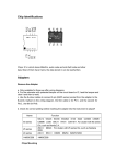
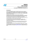
In I2C_GetBuffer, the ACK and STOP bits are automatically managed inside the function. In
I2C_GetByte you must manage the ACK and STOP bits as shown below, in order to receive
only one byte.
20/235
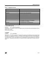
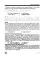
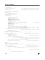
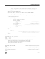
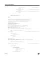
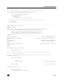
How to use the library
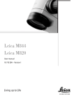
Figure 3. Flow-Chart for single byte reception in Master mode
I2C_Load_Address
(send slave address)
Waiting for completion of
event EV6 (wait for EVF=1)
Read I2CSR1
Clear ACK in I2CCR register
by using the function I2C_ACK
Wait for BTF = 1
Set STOP in I2CCR
I2C_GetByte
6.2.4 CAN
This Section gives an overview of the user guidelines for the CAN Library. The library provides
the software routines to use the CAN peripheral for ST72F561 device. The library is based on
the HIS / Vector CAN driver specification. The implemented function list is a subset of the functions described in the HIS / Vector CAN driver specification document.
21/235
How to use the library
6.2.4.1 DESCRIPTION
Files
Can.c - This file contains the CAN driver source code.
Can.h - This file contains the data structure, data type definitions and function prototypes for
the driver functions.
Can_hr.h - This file contains the #define statements for the driver functions.
User.c - This file contains the Global data declaration which is used by both driver as well as
application. For example - Tx & Rx buffers, Tx & Rx Id, Confirmation & Indication flags etc.
User.h - This file contains all user configurable parameters. For example- size of Tx & Rx
buffers, Number of Tx & Rx messages, hardware registers initialization values etc.
Note: User.c and User.h can be configured by the user depending on the application.
6.2.4.2 DATA STRUCTURES
Init Structure
Init structure contains the initialization values for the CAN controller registers. The user application may have more than one Init Structures which is configured by the parameter
NO_OF_INIT_HANDLES. The init handle is used as an index for the init structure.
Transmit Structure
The transmit structure contains the information about the transmitted message, for example
tx_Id, tx_dlc, tx_buffer. There is a separate table each for Id, dlc, pointer to tx_buffer. The
number of transmit structures depends on the number of messages to be transmitted in an application. It is configured by the parameter NO_OF_TX_HANDLES. The tx_handle is used as
an index for each transmit structure. The tx_identifier has two tables: one table each for
standard and extended identifiers. The tx_id, tx_dlc tables are configured by the user as per
the message to be transmitted. There is a single bit confirmation flag for each transmit message.
Receive Structure
The receive structure contains the information about the received message, for example
rx_Id, rx_dlc, rx_buffer. There is separate table each for Id, dlc, pointer to rx_buffer. The
number of receive structures depends up on number of messages to be received in an application. It is configured by the parameter NO_OF_RX_HANDLES. The rx_handle is used as an
index for each receive structure. The rx_identifier has two tables: one table each for standard
and ex tended identifiers. The identifier for the received message is stored inside this table by
the driver. The rx_dlc is configured by the user as per the length of the message. There is a
single bit indication flag and overflow flag for each received message.
22/235
How to use the library
6.2.4.3 DATA TYPES
The following are the data types used by the drivercanuint8
8-bit unsigned integer
canuint16
16-bit unsigned integer
There are some data types referenced while calling driver function CanInitHandle 8-bit unsigned integer (application-specific, depends on the number of configured initialization modes).
CanTransmitHandle 8-bit unsigned integer (application-specific, depends on the number of
transmit objects).
tCanMsgObject typedef volatile struct
{
canuint16 stdid;
canuint16 extid;
canuint8 dlc;
canuint8 data[8];
}
This is a transmit message structure referenced for the CAN driver service
CanMsgTransmit().
6.2.4.4 MEMORY USAGE
Constants
This includes the initialization values inside the Init Structure for the CAN controller registers,
transmit message information(tx_id, tx_dlc) inside the transmit structure, and receive message information(rx_dlc). These are stored in ROM.
Global Variables
These include the transmit & receive buffers, confirmation & indication flags, pointers to the Tx
& Rx buffers, and receive message id’s(rx_id).
6.2.4.5 PARAMETER CONFIGURATION
There are certain parameters that you have to configure depending on the application. These
parameters are configured inside the files user.c & user.h.
The following are the parameters that must be configured in the file user.h 1. NO_OF_TX_HANDLES - This parameter defines the number of messages to be transmitted by the application.
2. NO_OF_RX_HANDLES- The number of messages to be received by the application which
depends on the number of messages configured in the filter registers.
3. NO_OF_INIT_HANDLES- The number of initialization structures required in an application.
By default, its value is set to 1.
23/235
How to use the library
4. TX_MSGx_STDID - The standard id part for the MSGx to be transmitted, where x = transmit
message number.
5. TX_MSGx_EXTID - The extended id part for the MSGx to be transmitted, where x =
transmit message number.
6. TX_MSGx_DLC - The length for the MSGx to be transmitted, where x = transmit message
number. The maximum length that can be defined is 8.
7. RX_MSGx_DLC - The length for the MSGx to be received, where x = receive message
number. The maximum length that can be defined is 8.
8. REG_INITx_VALUE - The register initialization value for the CAN controller register, where
REG - register name, x = init structure number.
The following are the parameters that must be configured in the file user.c 1. MSGx_Tx_Buffer - This declares the buffer for the MSGx to be transmitted. The length of
the buffer is the same as defined by the parameter TX_MSGx_DLC in the file user.h. The
number of such buffers to be declared is the same as defined by the parameter
NO_OF_TX_HANDLES in the file user.h.
2. tx_stdid[ ] - This table stores the standard id value/s for the message/s to be transmitted.
The length of the table is the same as defined by the parameter NO_OF_TX_HANDLES and
the value/s stored inside is/are the same as defined by the parameter TX_MSGx_STDID in
the file user.h. If the message to be transmitted is Extended then above has to logical-ORed
with the EXT_ID_MASK(IDE bit), EXID17 & EXID16 bit values. As a result, the values stored
inside the table are in the same format as of MIDR0 & MIDR1 registers.
3. tx_extid[ ] - This table stores the extended id value/s for the message/s to be transmitted.
The length of the table is the same as defined by the parameter NO_OF_TX_HANDLES and
the value/s stored inside the table is/are the same as defined by the parameter
TX_MSGx_EXTID in the file user.h. It stores the values into the same format as of MIDR2 &
MIDR3 registers.
4. tx_dlc[ ] - This table stores the length for the message/s to be transmitted. The length of the
table is the same as defined by the parameter NO_OF_TX_HANDLES and the value/s stored
inside the table is/are the same as defined by the parameter TX_MSGx_DLC in the file user.h.
5. tx_data_ptr[ ] - This pointer table stores the address of transmit buffer/s (MSGx_Tx_buffer).
The length of the table is the same as defined by the parameter NO_OF_TX_HANDLES in the
file user.h.
6. MSGx_Rx_Buffer - This declares the buffer for the MSGx to be received. The length of the
buffer is the same as defined by the parameter RX_MSGx_DLC in the file user.h. Number of
such buffers to be declared is the same as defined by the parameter NO_OF_RX_HANDLES
in the file user.h.
24/235
How to use the library
7. rx_stdid - This declares the memory for storing the standard id part of the message to be received. The length of the table is the same as defined by the parameter
NO_OF_RX_HANDLES in the file user.h.
8. rx_extid - This declares the memory for storing the extended id part of the message to be received. The length of the table is the same as defined by the parameter
NO_OF_RX_HANDLES in the file user.h.
9. rx_dlc[ ] - This table stores the length for the message/s to be received. The length of the
table is the same as defined by the parameter NO_OF_RX_HANDLES and the value/s stored
inside the table is/are the same as defined by the parameter TX_MSGx_DLC in the file user.h.
10. rx_data_ptr[ ] - This pointer table stores the address of receive buffer/s
(MSGx_Rx_Buffer). The length of the table is the same as defined by the parameter
NO_OF_RX_HANDLES in the file user.h.
6.2.4.6 Tx & Rx BUFFER USAGE
Data can be accessed through the Tx & Rx buffers using the tx_handle & rx_handle as an
index. For example, data can be written into the MSGx_Tx_Buffer using the pointer
tx_data_ptr[x], where x = tx_handle for the message. Similarly, data can be received from
MSGx_Rx_Buffer using the pointer rx_data_ptr[x], where x = rx_handle for the message.
6.2.4.7 IMPLEMENTATION HINTS
– CanSleep( ) service must not be called when message transmission is in progress otherwise
sleep mode is not entered and service returns KCANFAILED. Also CanTransmit( ) service
shall not be called while the CAN driver is in sleep mode.
– Confirmation flag is set by the driver after the successful transmission of a message and flag
has to be cleared by the application. Application must call CanInterruptDisable( ) and CanInterruptRestore( ) services when clearing the confirmation flag in order to avoid CAN interrupt.
– Indication flag is set by the driver for a message received and this flag has to be cleared by
the application. Application must call CanInterruptDisable( ) and CanInterruptRestore( )
services when clearing the indication flag in order to avoid CAN interrupt.
– Overflow flag is set by the driver if the indication flag is not cleared by the application or message is not copied by the application from the global buffer into the application buffer.
If the overflow is set it means that the new message has been overwritten over the previous
message. Overflow flag has to be cleared by the application. Application must call CanInterruptDisable( ) and CanInterruptRestore( ) services when clearing the overflow flag in order to
avoid CAN interrupt.
– While copying data from receive buffer, application must call CanInterruptDisable( ) and
CanInterruptRestore( ) services in order to avoid a CAN interrupt. Similarly, while copying
25/235
How to use the library
data into the transmit buffer, application must call CanInterruptDisable( ) and
CanInterruptRestore( ) services to avoid an interrupt.
6.3 OTHER PERIPHERALS
6.3.1 TIMER
TIMERA and TIMERB can both be used simultaneously, depending on the TIMER selected.
You have to define USE_TIMERA and/or USE_TIMERB in ST7lib_config.h. Each function
name in the user manual contains TIMERx where x can be A or B depending on whether it is
for TIMERA or TIMERB. This is also explained in the example given at the end of the TIMER
library.
6.3.2 I/O
You must select the following parameters as per the device package.
#define IO_521_80PIN - Select this for an 80-pin package for ST72F521 device
ST7lib_config.h file.
#define IO_62_42PIN - Select this for a 42-pin package for ST72F62 device
ST7lib_config.h file.
#define IO_62_32PIN - Select this for a 32-pin package for ST72F62 device
ST7lib_config.h file.
If you are using other device packages, you must comment out these declarations
ST7lib_config.h file.
in
in
in
in
6.4 MEMORY MODELS
Limitation: in Cosmic, you are not allowed to use the same function in both the main program
and interrupt subroutine. This will give the error of Reentrant function in all memory models except mods and modsl.
6.5 PORTING APPLICATIONS FROM LIBRARY VERSION 1.0
Applications can be ported easily from ST7 Library Version 1.0 to ST7 LIbrary Version 2.0 by
making the following changes:
– Change the configuration files st7lib_config.h, default.env, .mak, .prm, and .lkf
– Add device_reg.o in compile list and link list in .mak, .prm and .lkf files
– Remove inclusion of periph_hr.h files from main to access device registers directly
– Replace use of TIMERA, TIMERB macros with USE_TIMERA, USE_TIMERB
– Replace ITC_EXT_ITSensitivity with ITC_ConfigureInterrupt
– Refer to the Release Notes for the list of changes in new version
26/235
Presentation of library functions
7 PRESENTATION OF LIBRARY FUNCTIONS
7.1 LIBRARY REFERENCES
Functions are described in the format given below:
Function name
Peripheral name and main functionality covered
Function prototype
Prototype declaration
Behaviour Description
Brief explanation of how the functions are executed
Input Parameters
Description of the parameters to be passed
Output Parameters
Value returned by the function
Required preconditions
Specific requirements to run the function
Functions called
Library Functions called
Post conditions
Function required to call immediately after this function
See also
Related functions for user reference
Note
Important points that you must take into consideration
Caution
Important points to be considered to avoid any failures
Code example
Example to show the proper way to use the library functions
27/235
Release Information
8 RELEASE INFORMATION
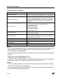
This release supports the following peripherals and devices.
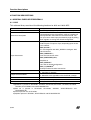
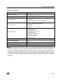
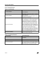
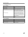
8.1 PERIPHERALS
– ADC (8-bit and 10bit): The on-chip Analog to Digital Converter (ADC) peripheral is a 10-bit,
successive approximation converter with internal sample and hold circuitry.
– SCI (with/without extended Baud Rate Pre scalar): The Serial Communications Interface
(SCI) offers a flexible means of full-duplex data exchange with external equipment requiring
an industry standard NRZ asynchronous serial data format.
– SPI: The Serial Peripheral Interface (SPI) allows fullduplex, synchronous, serial communication with external devices.
– I2C single/multi master: The Inter-Integrated Circuit Bus Interface serves as an interface between the microcontroller and the serial I2C bus.
– I2C Slave
– 16-bit Timer: The timer consists of a 16-bit free-running counter driven by a programmable
prescaler.
– 8-bit Timer: The timer consists of a 8-bit free-running counter driven by a programmable
prescaler.
– 8-bit Lite timer: The Lite Timer can be used for general-purpose timing functions.
– PWM ART 8-bit: The Pulse Width Modulated Auto-Reload Timer on-chip peripheral consists
of an 8-bit auto reload counter with compare/capture capabilities and of a 7-bit prescaler
clock source.
– AR 12-bit timer: The 12-bit Autoreload Timer can be used for general-purpose timing functions.
– TBU: The Timebase unit (TBU) can be used to generate periodic interrupts.
– WDG: The Watchdog timer is used to detect the occurrence of a software fault.
– ITC: The Interrupt Controller manages the hardware and software interrupts with flexible interrupt priority and level configuration.
– MCC: The Main Clock Controller consists of a programmable CPU clock prescaler, a clockout signal to supply external devices and a real time clock timer with interrupt capability.
– EEPROM: The Electrically Erasable Programmable Read Only Memory can be used as a
non volatile backup for storing data.
– I/Os: An I/O port contains up to 8 pins. Each pin can be programmed independently as digital
input (with or without interrupt generation) or digital output.
– CAN: The Controller area Network peripheral allows communication over a CAN network.
28/235
Release Information
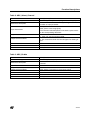
8.2 DEVICES
– ST72F62
– ST72F63B
– ST72F65
– ST72F521
– ST7FLITE0
– ST7FLITE1
– ST7FLITE2
– ST7FLITE3
– ST72F264
– ST72F561
– ST7SUPERLITE
– ST72325
– ST7232A
29/235
Function Descriptions
9 FUNCTION DESCRIPTIONS
9.1 GENERAL PURPOSE PERIPHERALS
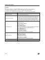
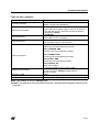
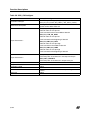
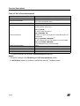
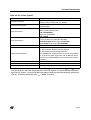
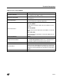
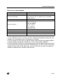
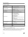
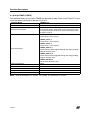
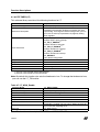
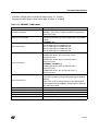
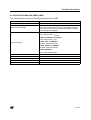
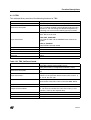
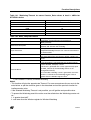
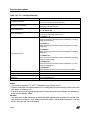
9.1.1 ADC
This software library consists of the following functions for 8-bit and 10-bit ADC.
Function Name
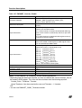
ADC_Init
Function Prototype
Void ADC_Init (Typ_ADC_InitParameter InitValue)
Behaviour Description
Initialization of the ADC, sets by default, channel to AIN0,
speed to default value of the device, ADC off, amplifier off,
interrupt disable and Continous conversion mode. You
can pass one or more input parameters by logically ORing
them together to change the default configuration.
ADC_SPEED 1)
Fadc=Fcpu/4 or Fcpu/2 or Fcpu, depending upon the device selected.
ADC_SLOW 2)
It is used together with ADC_SPEED to configure ADC
clock for device.
ADC_ONESHOT 3)
Input Parameters
One shot conversion active
ADC_AMPLIFIER_ON 4)
Amplifier on
ADC_DEFAULT
sets ADC in default configuration.
ADC_IT_ENABLE 3)
Interrupt enable for end of conversion.
Output Parameters
Required Preconditions
None
1. Configure IO properly.
2. Selection of the right ADC in the file ST7lib_config.h
Functions called
None
Postconditions
ADC correctly configured
See also
ADC_Enable and ADC_Select_Channel
1)Speed bit is present in ST72F561, ST72F62, ST72F264, ST72F521, ST72325, ST7232A,
ST7DALI, ST7FLITE0/1/2/3 and ST7SUPERLITE.
2)Slow bit is present in ST72F561, ST72F264, ST7DALI, ST7FLITE0/1/2/3 and
ST7SUPERLITE.
3)Feature present only in ST72F62.
4)Amplifier present in ST7DALI, ST7FLITE0/1/2 and ST7SUPERLITE.
30/235
Function Descriptions
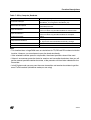
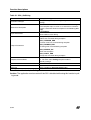
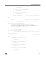
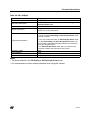
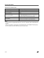
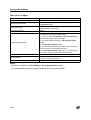
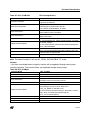
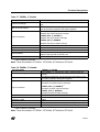
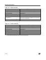
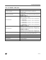
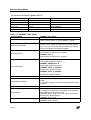
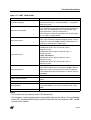
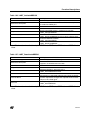
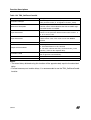
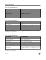
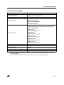
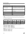
Table 2. ADC_Select_Channel
Function Name
ADC_Select_Channel
Function Prototype
Void ADC_Select_Channel (unsigned char ADC_AIN)
Behaviour Description
Selects the conversion channel by passing the channel
number as input parameter
ADC_AIN
Input Parameters
Output Parameters
ADC_AIN is in the range [0:15]
The channel number depends on the device, please refer
to the corresponding datasheet.
None
1. ‘ADC_Init’ must have been called.
Required Preconditions
2. The selected channel must be configured as floating input.
Functions called
None
Postconditions
ADC channel selected
See also
ADC_Enable
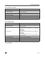
Table 3. ADC_Enable
Function Name
ADC_Enable
Function Prototype
Void ADC_Enable (void)
Behaviour Description
Switches on the ADC to start conversion on the selected
channel.
Input Parameters
None
Output Parameters
None
Required Preconditions
ADC_Select_Channel must have been called.
Functions called
None
Postconditions
ADC conversion started
See also
ADC_Disable
31/235
Function Descriptions
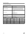
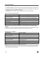
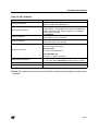
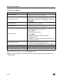
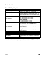
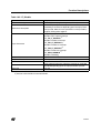
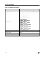
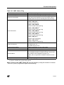
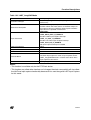
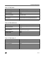
Table 4. ADC_Test_Conversn_Complete
Function Name
ADC_Test_Conversn_Complete
Function Prototype
BOOL ADC_Test_Conversn_Complete (void)
Behaviour Description
Returns the latest status of conversion
Input Parameters
None
Output Parameters
TRUE: conversion completed
FALSE: conversion not completed
Required Preconditions
ADC_Enable must have been called.
Functions called
None
Postconditions
If TRUE, ADC conversion is complete and you can call the
ADC_Conversn _Read.
If FALSE, ADC conversion not completed.
This function can be looped until the conversion is complete.
See also
ADC_Disable, ADC_Conversn_Read
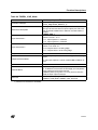
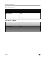
Table 5. ADC_Conversn_Read
Function Name
ADC_Conversn_Read
For 10-bit ADC,
Function Prototype
unsigned int ADC_Conversn_Read (void)
For 8-bit ADC,
unsigned char ADC_Conversn_Read (void)
Behaviour Description
Reads the converted digital value from the data register.
Input Parameters
None
Output Parameters
Data Register value (it depends upon the device selected,
please refer to the corresponding data sheet).
Required Preconditions
ADC_Test_Conversn_Complete must have been called.
Functions called
None
1. EOC flag is cleared.
Postconditions
2. Equivalent digital value available in the data register is
returned.
See also
None
Note: The EOC flag may be set again during the execution of this function, this depends on
the conversion time.
32/235
Function Descriptions
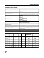
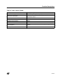
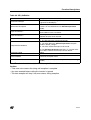
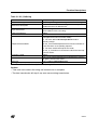
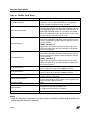
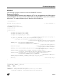
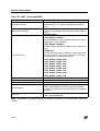
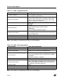
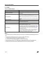
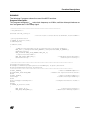
Table 6. ADC_Disable
Function Name
ADC_Disable
Function Prototype
Void ADC_Disable (void)
Behaviour Description
Stops ADC conversion on the selected channel.
Input Parameters
None
Output Parameters
None
Required Preconditions
ADC is switched on
Functions called
None
Postconditions
ADC switched off
See also
ADC_Enable
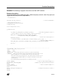
Example:
The following C program shows the use of the ADC functions.
Program description:
This program converts the analog value on channel 5 of the ST72F62 device to a digital value.
/* Program start */
#include “st7lib_config.h”
void main (void);
void main(void)
{
unsigned int Conv_Data1;
unsigned char channel = 5;
/* Select st72F62 device
/* Variable to get the converted digital value
*/
*/
ADC_Init ((unsigned char )ADC_SPEED | (unsigned char )ADC_ONESHOT); /* FADC= FCPU/4 */
ADC_Select_Channel (channel);
/* Channel 5 selected */
ADC_Enable ();
/* Start conversion */
while (ADC_Test_Conversn_Complete () == FALSE);
Conv_Data1 = ADC_Conversn_Read ();
/* Read the converted value */
ADC_Disable () ;
Nop;
/* Macro defined in st7lib_config.h
*/
}
/* Program end */
33/235
Function Descriptions
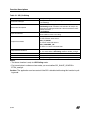
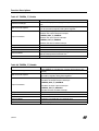
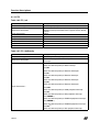
9.1.2 SCI
This Library supports 2 SCI of ST72F561 device and 1 SCI on all other devices.
For devices with only one SCI no suffix “x” is used in the function names.
For 2nd SCI of ST72F561 you must replace suffix “x” in the function names with 2.
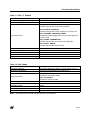
Function Name
SCIx_Init
Function Prototype
Void SCIx_Init (SCI_Type_Param1 Init_Value1,
SCI_Type_Param2 Init_Value2)
Behaviour Description
Initialization of SCI, sets by default receiver sleep off, no break
character will be transmitted, wakeup from sleep by idle frame
detection, Parity disabled, 8-bit transmission mode and Receiver
in active mode. You can select the parity, 9-bit transmission
mode, Receiver wakeup, Receiver Mute and Break Enable feature through properly selecting the Init_Value1 and Init_Value2.
SCI_ODPARITY_SELECT
Select odd Parity
SCI_EVPARITY_SELECT
Select even parity
SCI_WAKEUP_ADDR
Input Parameter 1
Receiver wake up from mute mode while address mark is detected(i.e MSBit of the data transmitted should be 1)
SCI_WORDLENGTH_9
Select 9-bit transmission
SCI_DEFAULT_PARAM1
Load the register with the default value(0x00)
SCI_MUTE_ENABLE
Receiver in mute mode
Input Parameter 2
SCI_BREAK_ENABLE
Transmit break characters
SCI_DEFAULT_PARAM2
Load the register with the default value(0x00)
Output Parameter
None
Required Preconditions
SCI port pin should be configured properly.
34/235
Function Descriptions
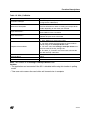
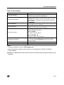
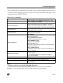
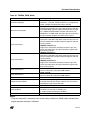
Table 7. SCIx_Compute_Baudrate
Function Name
SCIx_Compute_Baudrate
Function Prototype
Void SCIx_Compute_Baudrate(unsigned int
BaudRate_Tx, unsigned int BaudRate_Rx)
Behaviour Description
Selects Transmitter/ Receiver baudrate for the SCI without
extended prescaler.
Input Parameter 1
Input Parameter 2
Output Parameter
Required Preconditions
BaudRate_Tx*
You can select any possible baudrate for transmission.
BaudRate_Rx*
You can select any possible baudrate for reception.
None
1. SCIx_Init, must have been called.
2. fcpu must have been defined in ST7lib_Config.h
Functions called
None
Postconditions
None
Note:
– This function takes a large ROM area as calculations for TR, RR and PR are done inside the
function. However, you can choose to pass the baudrate directly.
– If the selected baudrate speed is not possible, the closest possible value will be used.
– If there is no common prescalar factor for receiver and transmitter baudrates, then you will
get the nearest possible receiver baudrate, at the prescalar division factor selected for the
transmitter.
– In half Duplex mode you can pass the same transmitter and receiver baudrates to get the
exact Tx/Rx baudrate (whichever mode you are using)
35/235
Function Descriptions
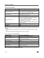
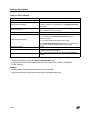
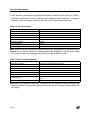
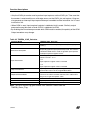
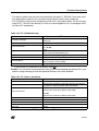
Table 8. SCIx_Select_Baudrate
Function Name
SCIx_Select_Baudrate
Function Prototype
Void SCIx_Select_Baudrate (SCI_Baudrate_Type
Baudrate_Prescaler)
Behaviour Description
Selects Transmit/Receive baudrate for SCI without extended baudrate prescaler. You have to define all the
prescaler parameters corresponding to the desired
baudrate speed. You have to pass the three input parameters by logically ORing them to select the baudrate.
SCI_PR_X
X=1,3, 4,13
SCI_TR_Y
Input Parameters
Y=1,2,4,8,16,32,64,128
SCI_RR_Z
Z=1,2,4,8,16,32,64,128
Output Parameter
None
1.SCIx_Init must have been called
Required Preconditions
2. You have to specify the PR, RR and TR values for the
desired baudrate
Functions called
None
Postconditions
Refer to the table below.
SCI_PR_X
SCI_TR_Y
SCI_RR_Z
Transmitter baudrate
speed
Receiver baudrate
Speed
SCI_PR_13
SCI_TR_1
SCI_RR_1
38400
38400
SCI_PR_13
SCI_TR_2
SCI_RR_2
19200
19200
SCI_PR_13
SCI_TR_4
SCI_RR_4
9600
9600
SCI_PR_13
SCI_TR_8
SCI_RR_8
4800
4800
SCI_PR_13
SCI_TR_16
SCI_RR_16
2400
2400
SCI_PR_13
SCI_TR_32
SCI_RR_32
1200
1200
Note: This function saves the ROM area but you have to pass the values for the TR,PR RR.
36/235
Function Descriptions
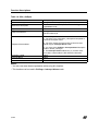
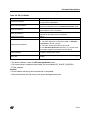
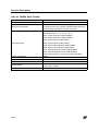
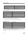
Table 9. SCIx_Extend_Baudrate
Function Name
SCIx_Extend_Baudrate
Function Prototype
Void SCIx_Extend_Baudrate (SCI_Baudrate_Type
Baudrate_Prescaler, unsigned char EPTR, unsigned char
EPRR)
Behaviour Description
Selects Transmit/Receive baudrate for SCI with extended
baudrate prescaler. You have to define all the prescaler
parameters corresponding to the desired baudrate speed.
SCI_PR_X
X=1,3, 4,13
SCI_TR_Y
Input Parameter 1
Y=1,2,4,8,16,32,64,128
SCI_RR_Z
Z=1,2,4,8,16,32,64,128
EPTR
Input Parameter 2
Select any value from 0 to 255
EPRR
Input Parameter 3
Select any value of EPRR from 0 to 255
Output Parameter
None
1.SCIx_Init must have been called
Required Preconditions
2. You have to specify the PR, RR and TR values for the
desired baudrate
Functions called
None
Postconditions
Refer to the table below.
SCI_PR_X
TR_Y
RR_Z
EPTR
EPRR
Transmitter
baudrate speed
Receiver
baudrate
Speed
SCI_PR_13
SCI_T
R_1
SCI_RR
_1
1
1
38400
38400
SCI_PR_13
SCI_T
R_2
SCI_RR
_2
2
2
9600
9600
SCI_PR_13
SCI_T
R_4
SCI_RR
_4
3
3
3200
3200
SCI_PR_13
SCI_T
R_8
SCI_RR
_8
4
4
1200
1200
SCI_PR_13
SCI_T
R_16
SCI_RR
_16
5
5
480
480
SCI_PR_13
SCI_T
R_32
SCI_RR
_32
6
6
200
200
37/235
Function Descriptions
Table 10. SCIx_IT_Enable
Function Name
SCIx_IT_Enable
Function Prototype
Void SCIx_IT_Enable (SCI_IT_Type SCI_IT_Param)
Behaviour Description
Selects SCI interrupts
SCI_IDLE_LINE
Enable interrupt due to idle frame reception.
SCI_RECEIVE_OVERRUN
Enable interrupt due to data reception or overrun error.
SCI_TRANSMIT_REGISTER_READY
Input Parameters
Enable interrupt when transmit data register is ready to
load.
SCI_FRAME_TRANSMITTED
Enable Interrupt due to Transmission completetion.
SCI_PARITY_ERROR
Enable Interrupt due to Parity Error.
Output Parameter
Required Preconditions
Functions called
None
1. SCIx_ComputeBaudrate or SCIx_SelectBaudrate must
have been called.
2. You should reset the interrupt mask with EnableInterrupts.
None
Postconditions
None
See also
None
38/235
Function Descriptions
Table 11. SCIx_IT_Disable
Function Name
SCIx_IT_Disable
Function Prototype
Void SCIx_IT_Disable (SCI_IT_Type SCI_IT_Param)
Behaviour Description
Disables SCI interrupts
SCI_IDLE_LINE
Disable interrupt due to idle frame reception.
SCI_RECEIVE_OVERRUN
Disable interrupt due to data reception or overrun error.
SCI_TRANSMIT_REGISTER_READY
Input Parameters
Disable interrupts triggered when transmit data register is
ready to load.
SCI_FRAME_TRANSMITTED
Disable Interrupt due to Transmission completion.
SCI_PARITY_ERROR
Disable Interrupt due to Parity Error.
Output Parameters
None
Required Preconditions.
The baudrate must have been selected
Functions called
None
Postconditions
None
See also
None
Table 12. SCIx_Mode
Function Name
SCIx_Mode
Function Prototype
Void SCIx_Mode (SCI_Mode_Type SCI_Mode_Param)
Behaviour Description
Enables Transmitter/Receiver mode of SCI.
SCI_TX_ENABLE
Input Parameter
Enable the Transmitter mode.
SCI_RX_ENABLE
Enable the Receiver mode.
Output Parameter
None
Required Preconditions
SCIx_IT_Enable must have been called for interrupt mode
Functions called
None
Postconditions
None
See also
None
Note: To disable the SCI Mode, select the SCIx_Init function.
39/235
Function Descriptions
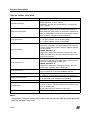
Table 13. SCIx_PutByte
Function Name
SCIx_PutByte
Function Prototype
Void SCIx_PutByte (unsigned char Tx_Data)
Behaviour Description
Transmits a single byte of data polling mode or interrupt
driven mode.
Input Parameters
Output Parameters
Tx_Data
Data byte to be transmit.
None
1. SCIx_Mode must have been called.
2. SCIx_IsTransmitCompleted must have been called
(Refer to example on page 53 for more details).
Required Preconditions
3. You must enable the interrupt due to Transmit Complete/Transmit Data Ready Flag for the Interrupt driven
mode
4. You must select Polling or Interrupt driven Transmission mode in ST7lib_config.h
Functions called
None
Postconditions
None
See also
None
Notes:
– You can use some timeout protection while using this function.
– This function is for Polling or Interrupt driven mode.
Table 14. SCIx_IsTransmitCompleted
Function Name
SCIx_IsTransmitCompleted
Function Prototype
BOOL SCIx_IsTransmitCompleted (void)
Behaviour Description
Checks for the completion of current byte transmission.
Returns TRUE if byte transmission is completed otherwise
returns FALSE.
Input Parameters
None
Output Parameters
Boolean
Required Preconditions
SCIx_PutByte must have been called.
Functions called
None
Postconditions
None
See also
None
Note: This function is for Polling mode.
40/235
Function Descriptions
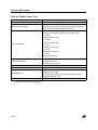
Table 15. SCIx_PutBuffer
Function Name
SCIx_PutBuffer
Function Prototype
Void SCIx_PutBuffer(const unsigned char *PtrToBuffer,
unsigned char NbOfBytes)
Behaviour Description
Starts transmission from the user buffer. The data transmission will be driven either in Polling or Interrupt driven
mode depending on the mode you selected.
Input Parameter 1
Input Parameter 2
Output Parameter
*PtrToBuffer
Start address of the user buffer
NbOfBytes
Number of bytes to be transmitted
None
1. SCIx_Mode must have been called.
2. You must enable the interrupt due to Transmit Data
Ready Flag for the Interrupt driven mode
Required Preconditions
3. You must select the Polling or Interrupt driven transmission mode in ST7lib_Config.h file.
4. The SCIx_IT_Function must have been called inside
the SCI interrupt subroutine.
Functions called
SCIx_IsTransmitCompleted
Postconditions
None
See also
None
Note: This function is for Polling or Interrupt driven mode.
Caution:
– The application can lose control if the SCI is disabled while using this function in polling
mode.
– Take care not to access the user buffer until transmission is complete.
41/235
Function Descriptions
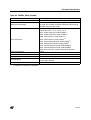
Table 16. SCIx_PutString
Function Name
SCIx_PutString
Function Prototype
Void SCIx_PutString (const unsigned char *PtrToString)
Behaviour Description
Starts transmission of a string passed by the user. The
data transmission will be through polling or interrupt driven
modes depending on the mode you selected.
Input Parameters
Output Parameters
*PtrToString
Start address of the user string
None
1. SCIx_Mode must have been called.
2. You must enable the interrupt due to Transmit Data
Ready Flag for Interrupt driven mode.
Required Preconditions
3. You must select the transmission mode Polling or Interrupt driven in ST7lib_Config.h.
4. SCIx_IT_Function must have been called inside the SCI
interrupt subroutine.
Functions called
SCIx_IsTransmitCompleted
Postconditions
None
See also
None
Note: This function is for Polling or Interrupt driven mode.
Caution:
– The application can lose control if the SCI is disabled while using this function in polling
mode.
– Take care not to access the string until transmission is complete.
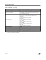
Table 17. SCIx_IsTransmitCompleted
Function Name
SCIx_IsTransmitCompleted
Function Prototype
BOOL SCIx_IsTransmitCompleted (void)
Behaviour Description
Checks for the completion of data transmission. It returns
FALSE till all the data bytes have been transmitted and
TRUE when the request is over.
Input Parameters
None
Output Parameters
Boolean
Required Preconditions
Transmission must have been requested.
Functions called
None
Postconditions
SCIx_PutByte/SCIx_PutBuffer/SCIx_PutString must be
called after this function
See also
None
Note: This function is for Interrupt driven mode.
42/235
Function Descriptions
Table 18. SCIx_9thBit_TxRx
Function Name
SCIx_9thBit_TxRx
Function Prototype
BOOL SCIx_9thBit_TxRx (BOOL Bit9_Val)
Behaviour Description
This function configures the 9th bit to be transmitted as 0
or 1 for 9-bit transmission. Also it returns the status of the
9th bit in the 9-bit reception mode.
TRUE
Input Parameters
If 1 is to be transmitted as 9th bit.
FALSE
If 0 is to be transmitted as 9th bit.
TRUE
Output Parameters
If 9th bit received is 1.
FALSE
If 9th bit received is 0.
1.SCI must be configured in 9 bit mode.
Required Preconditions
2.For reception function SCIx_GetString/SCIx_GetBuffer/
SCIx_GetByte must have been called before this function.
Functions called
None
Postconditions
For transmission SCIx_PutByte/SCIx_PutBuffer/
SCIx_PutString must be called after this function.
See also
None
Notes:
– In transmission, the return value of the function is ignored. In reception, the input parameter
is not significant.
– You must call this function while using 9 bit mode.
– The Status of the 9th bit remains same during the complete buffer/string transmission.
– You can change the status of 9th bit in the next request.
43/235
Function Descriptions
Table 19. SCIx_GetByte
Function Name
SCIx_GetByte
Function Prototype
Unsigned char SCIx_GetByte (void)
Behaviour Description
Returns the most recent Byte received in Polling or Interrupt driven mode.
Input Parameters
None
Output Parameters
Unsigned char
Received data byte
1. The SCIx_Mode must have been called
2. You must have called SCIx_IsReceptionCompleted to
check the reception status.
Required Preconditions
3. You must enable the interrupt due to Receive Data
Ready flag for Interrupt driven mode.
4. You must select Polling or Interrupt driven Reception
mode in ST7lib_Config.h.
5. For Interrupt driven mode SCIx_IT_Function must
have been called inside the SCI interrupt subroutine.
Functions called
None
Postconditions
None
See also
None
Notes:
– You can use some timeout protection while using this function.
– This function can be used in Polling or Interrupt driven mode.
44/235
Function Descriptions
Table 20. SCIx_GetBuffer
Function Name
SCIx_GetBuffer
Function Prototype
SCI_RxError_t SCIx_GetBuffer (unsigned char *PtrToBuffer, unsigned char NbOfBytes)
Behaviour Description
Receives a number of data bytes and stores them in the
user buffer. The reception stops as soon as an error occurs and error status is returned. The data reception is
controlled by polling.
Input Parameter 1
Input Parameter 2
*PtrtoBuffer
Start address of the user buffer
NbOfBytes
Total number of bytes to be received
SCI_NOISE_ERR
Noise error occurred during transmission.
SCI_OVERRUN_ERR
Overrun error occurred during reception
Output Parameters
SCI_FRAMING_ERR
Framing error occurred during reception
SCI_PARITY_ERR
Parity error occurred during reception
SCI_RECEIVE_OK
Error free reception
1.The SCIx_Mode must have been called.
Required Preconditions
2.You must select Polling reception mode in
ST7lib_Config.h
Functions called
None
See also
SCIx_GetBuffer (Interrupt driven mode)
Note: This function is only for Polling mode
Caution: The application can lose control if the SCI is disabled while using this function in polling mode.
45/235
Function Descriptions
Table 21. SCIx_GetString
Function Name
SCIx_GetString
Function Prototype
SCI_RxError_t SCIx_GetString (unsigned char *PtrToString)
Behaviour Description
Receives and stores the data in the user-defined string.
The reception stops as soon as an error occurs and error
status is returned. The data reception is controlled by polling.
Input Parameters
*PtrToString
Start address of the String
SCI_NOISE_ERR
Noise error occurred during reception.
SCI_OVERRUN_ERR
Overrun error has occurred during reception
Output Parameters
SCI_FRAMING_ERR
Framing error occurred during reception
SCI_RECEIVE_OK
Error free reception
SCI_PARITY_ERR
Parity error occurred during reception
1. SCIx_Mode must have been called
Required Preconditions
2. You must select Polling reception mode in
ST7lib_Config.h
Functions called
None
Postconditions
None
See also
SCIx_GetString (Interrupt driven mode)
Note: This function is only for Polling mode
Caution: The application can lose control if the SCI is disabled while using this function in polling mode.
46/235
Function Descriptions
Table 22. SCIx_GetBuffer
Function Name
SCIx_GetBuffer
Function Prototype
Void SCIx_GetBuffer (unsigned char *PtrToBuffer, unsigned char NbOfBytes)
Behaviour Description
Starts reception of the bytes and stores it into the userbuffer in interrupt driven mode.
Input Parameter 1
Input Parameter 2
Output Parameters
*PtrToBuffer
Start address of the user buffer
NbOfBytes
Total number of bytes to be received
None
1. The SCIx_Mode must have been called
2. You must enable the interrupt due to Receive Data
Ready flag.
Required Preconditions
3. You must select the Interrupt driven reception mode in
ST7lib_Config.h
4. SCIx_IT_Function must have been called inside the SCI
interrupt subroutine.
Functions called
None
Postconditions
You must call SCIx_IsReceptionCompleted after this function to check the reception status.
See also
SCIx_GetBuffer (Polling mode)
Note: This function is only for Interrupt driven mode.
Caution:
– Take care not to access the user buffer until reception is completed.
– Any data received before calling this function is ignored
– The data reception will stop as soon as an error occurs.
47/235
Function Descriptions
Table 23. SCIx_GetString
Function Name
SCIx_GetString
Function Prototype
Void SCIx_GetString (unsigned char *PtrToString)
Behaviour Description
Reception of data string starts through interrupt driven
mode
Input Parameters
Output Parameters
*PtrToString
Start address of the location where string is to be placed.
None
1. SCIx_Mode must have been called
2. You must enable the interrupt due to Receive Data
Ready flag.
Required Preconditions
3. You must select the Interrupt driven reception mode in
ST7lib_Config.h.
4. SCIx_IT_Function must have been called inside the SCI
interrupt subroutine.
Functions called
None
Postconditions
You must call SCIx_IsReceptionCompleted after this function to check the reception status.
See also
SCIx_GetString (Polling mode)
Note: This function is only for Interrupt driven mode.
Caution:
– Take care not to access the user buffer until reception is completed
– Any data received before calling this function is ignored
– The data reception will stop as soon as an error occurs.
48/235
Function Descriptions
Table 24. SCIx_IsReceptionCompleted
Function Name
SCIx_IsReceptionCompleted
Function Prototype
SCI_RxError_t SCIx_IsReceptionCompleted(void)
In Interrupt driven mode, this function checks for the
completion of reception of a set of data or the occurrence
of an error and returns the reception status.
Behaviour Description
Input Parameter
In both Polling and Interrupt driven modes, the function
checks if a single byte of data is received and ready for
processing. It returns SCI_RX_DATA_EMPTY until the
data byte is received and returns the reception status afterwards.
None
SCI_BUFFER_ONGOING 1)
User buffer is not full
SCI_STRING_ONGOING 1)
Complete string is not received in the user buffer
SCI_NOISE_ERR
Noise error occurred during reception.
SCI_OVERRUN_ERR
Output Parameters
Overrun error occurred during reception
SCI_FRAMING_ERR
Framing error occurred during reception
SCI_RECEIVE_OK
Error free data is stored in the user buffer
SCI_PARITY_ERR
Parity error occurred during reception
SCI_RX_DATA_EMPTY 2)
No data byte is received.
Required Preconditions
None
Functions called
None
Postconditions
For single byte reception, if the byte is received, then
SCIx_GetByte can be called after this function.
1) These Parameters are returned in Interrupt driven mode only.
2) This Parameter is returned in case of single byte reception only, for both Polling and Interrupt driven modes.
Notes:
– If this function is called before any reception request is made, it will check for single byte reception, and will return SCI_RX_DATA_EMPTY until the data byte is received, and returns
the reception status afterwards.
49/235
Function Descriptions
– If a reception request for a set of data is over, this function will return the error status of that
request only once. If this function is called again (before making next reception request), then
the function will check for single byte reception.
– In Polling mode, this function is used in conjunction with SCIx_GetByte only.
Table 25. SCIx_Forced_Clear_Flag
Function Name
SCIx_Forced_Clear_Flag
Function Prototype
Void SCIx_Forced_Clear_Flag(void)
Behaviour Description
Clears all the status and Error flags (TC, TDRE, RDRF,
IDLE, OR, NF, FE, PE) in SCI Status register(SCISR).
Input Parameters
None
Output Parameters
None
Required Preconditions.
Transmission or Reception must have taken place.
Functions called
None
Postconditions
None
See also
None
Note: You can call this function whenever you want to force the error and status flags be
cleared.
Caution: Do not call this function if a reception request is ongoing as it will corrupt the reception status by clearing all the flags and you will not receive any error status.
Table 26. SCIx_IT_Function
Function Name
SCIx_IT_Function
Function Prototype
Void SCIx_IT_Function (void)
Behaviour Description
Transmits or receives data in Interrupt driven mode. You
must call this function inside the interrupt service routine.
Input Parameters
None
Output Parameters
None
Required Preconditions.
You must have called transmission or reception function in
Interrupt driven mode.
Functions called
None
Postconditions
Communication is started inside the interrupt subroutine.
See also
None
Note: Only use this function in the Interrupt service routine.
Caution: Special care must be taken, while you write your own code along with this function
in the interrupt service routine, otherwise, data transfer synchronisation could be affected,
which may lead to data corruption.
50/235
Function Descriptions
Table 27. SCI2_Clkout_Enable
Function Name
SCI2_Clkout_Enable
Function Prototype
Void SCI2_Clkout_Enable (void)
Behaviour Description
This function enables the ClockOutput of SCI2 of
ST72F561 device.
Input Parameters
None
Output Parameters
None
Required Preconditions.
None
Functions called
None
Postconditions
SCI clock is availaible at a dedicated pin during communication.
See also
None
51/235
Function Descriptions
Table 28. SCI2_ClkConfigure
Function Name
SCI2_ClkConfigure
Function Prototype
Void SCI2_ClkConfigure(SCI_PO_PH_t
SCI_PO_PH_Param, SCI_LBCL_t SCI_LBCL_Param)
Behaviour Description
Configures the Polarity, Phase and numbers of Clock
pulses for the SCI2 Clock out.
SCI_PO_LOW_PH_LOW
Default value on CLK pin low
CLK activated at the in the middle of data bit
SCI_PO_LOW_PH_HIGH
Default value on CLK pin low
Input Parameter 1
CLK activated at the beginning of data bit
SCI_PO_HIGH_PH_LOW
Default value on CLK pin High
CLK activated in the middle of data bit
SCI_PO_HIGH_PH_HIGH
Default value on CLK pin high
CLK activated at the beginning of data bit
SCI_LBCL_DISABLE
Input Parameter 2
The CLK pulse of last data bit is not output to the pin
SCI_LBCL_ENABLE
The CLK pulse of last data bit is output to the pin
Output Parameters
None
Required Preconditions.
None
Functions called
None
Postconditions
SCI clock is availaible at a dedicated pin during communication.
See also
None
52/235
Function Descriptions
EXAMPLE:
The following C program shows how the SCI functions are used.
This program runs the following sequence for an SCI without extended baudrate prescaler for
polling or interrupt driven mode:
– transmits a single byte passed by the user
– transmits the 20 bytes of data at the baudrate 9600
– receives 20 bytes of data at a baud rate of 9600.
Note: You must define the communication mode and cpu speed (Fcpu) in the ST7lib_config.h
file.
You can select any of the communication speeds from the following list :
SCI_POLLING_TX
-- For Transmission mode
SCI_POLLING_RX
-- For Reception mode
SCI_ITDRV_WITHOUTBUF_TX
-- For Transmission
SCI_ITDRV_WITHOUTBUF_RX
-- For Reception
/* You can use a timeout function to handle the fault in which the control will get stuck in side
a loop.This function should have the Boolean return, i.e it should return TRUE if the expected
wait Time is not elapsed and FALSE if it is elapsed.*/
Software Control
Wait loop
User timeout
Function
/*============================================================*/
The following variables are declared in main.h file.
main.h:
#ifndef MAIN
#define MAIN
void Userfunction(void);
BOOL User_Timeout_Function(void);
void sci_rt (void);
/*Declaration of user function*/
#endif
/*============================================================*/
53/235
Function Descriptions
/* Program start */
#include "ST7lib_Config.h"
#include "main.h"
/*List of all ST7 devices and communication mode*/
/*Declaration of all the functions used in main.c*/
#define Buf_Size ((unsigned char)20)
void main(void);
static unsigned int Timeoutcount;
unsigned char Buff_Rcv[20]= {"
"} ;
void main (void)
{
unsigned char Rx_Data = 0;
unsigned char NbOfBytes = 20;
unsigned char Tx_Data = 51;
unsigned int BaudRate_Tx = 9600;
unsigned int BaudRate_Rx = 9600;
SCI_RxError_t Err = 0;
/*user buffer*/
unsigned char Buff[Buf_Size]= "SCI DRIVERS TESTING";
unsigned char new[] = "\n\r";
BOOL Bool_Temp1 ;
BOOL Bool_Temp2 ;
Timeoutcount = 0;
SCI_Init(SCI_DEFAULT_PARAM1, SCI_DEFAULT_PARAM2);
SCI_Compute_Baudrate(BaudRate_Tx,BaudRate_Rx);
/*Selects the transmission reception baudrate as 9600*/
// SCI_Extend_Baudrate (SCI_PR_13+SCI_TR_2+SCI_RR_2,0x02,0x02);
/* Selects transmission reception baudrate as 9600*/
EnableInterrupts
/*----------------------------------------------------------------------------Transmission through Polling mechanism
-----------------------------------------------------------------------------*/
#ifdef SCI_POLLING_TX
/*Selects polling mode for transmission*/
SCI_Mode(SCI_TX_ENABLE);
SCI_PutByte(Tx_Data);
/*Single Byte transmission*/
Bool_Temp1 = (SCI_IsTransmitCompleted());
/* this function causes a volatile variable to change,hence it cannot be
put as a right side operand in a conditional stmt */
while ( (User_Timeout_Function()) && (!(Bool_Temp1)));
SCI_PutBuffer( Buff,NbOfBytes);
/*Continuous buffer transmission*/
#endif
/*----------------------------------------------------------------------------Reception Through Polling mechanism
-----------------------------------------------------------------------------*/
#ifdef SCI_POLLING_RX
/*Selects polling mode for reception*/
SCI_Mode(SCI_RX_ENABLE);
/* Enable the receiver mode of SCI*/
/*-----------------------------Single Byte Reception-------------------------*/
/*Wait for data reception*/
do
{
Err = SCI_IsReceptionCompleted();
54/235
Function Descriptions
} while ((User_Timeout_Function()) && (Err == SCI_RX_DATA_EMPTY) );
if(User_Timeout_Function())
/*Byte received before Timeout */
{
if(Err == SCI_RECEIVE_OK)
{
Rx_Data = SCI_GetByte();
/*Correct Data Byte received*/
Nop
}
else
{
if((unsigned char)Err & SCI_NOISE_ERR)
{
Userfunction ();
}
if((unsigned char)Err & SCI_OVERRUN_ERR)
{
Userfunction ();
}
if((unsigned char)Err & SCI_FRAMING_ERR)
{
Userfunction ();
}
if((unsigned char)Err & SCI_PARITY_ERR)
{
Userfunction ();
}
/*Corrupted Data Byte received*/
Rx_Data = SCI_GetByte();
}
}
/*Timeout elapsed*/
else
{
while(1);
/*Transmitter or Receiver having problem */
}
/*----------------------------Buffer Reception-------------------------------*/
Err = (SCI_GetBuffer(Buff_Rcv,(unsigned char)19));
/*Reception of data in user buffer*/
if(Err == SCI_RECEIVE_OK)
/*Checks the error status*/
{
Nop
/* Reception OK*/
}
else
/*Error Ocurred during reception*/
{
if((unsigned char)Err & SCI_NOISE_ERR)
{
Userfunction ();
}
if((unsigned char)Err & SCI_OVERRUN_ERR)
{
Userfunction ();
}
if((unsigned char)Err & SCI_FRAMING_ERR)
{
55/235
Function Descriptions
Userfunction ();
}
if((unsigned char)Err & SCI_PARITY_ERR)
{
Userfunction ();
}
}
#endif
/*----------------------------------------------------------------------------Transmission through Interrupt Driven without Buffer mode
-----------------------------------------------------------------------------*/
#ifdef SCI_ITDRV_WITHOUTBUF_TX
/*Selects interrupt mode for transmission*/
/*Interrupt enable when TDRE flag is set */
SCI_Mode(SCI_TX_ENABLE);
if(SCI_IsTransmitCompleted())
{
SCI_PutByte((unsigned char)55);
while (!(SCI_IsTransmitCompleted()));
SCI_PutString(Buff);
/*user pointer is copied to the global pointer*/
/* Here,user can perform other tasks or operations except transmission till the
time transmission is complete,after which user can perform transmission again*/
while (!(SCI_IsTransmitCompleted()));
}
#endif
/*----------------------------------------------------------------------------Reception through Interrupt driven without Buffer mechanism
-----------------------------------------------------------------------------*/
#ifdef SCI_ITDRV_WITHOUTBUF_RX
/* Selects interrupt mode for transmission */
/*Interrupt enable when RDR register is ready to read*/
SCI_IT_Enable((unsigned char)SCI_RECEIVE_OVERRUN);
SCI_Mode(SCI_RX_ENABLE);
/*----------------------------Single Byte reception--------------------------*/
do
{
Err = SCI_IsReceptionCompleted();
}while ((User_Timeout_Function()) && (Err == SCI_RX_DATA_EMPTY) );
/* Wait for the completion of current data byte reception*/
if(User_Timeout_Function())
{
if(Err == SCI_RECEIVE_OK)
{
/*Reception OK */
Nop
Rx_Data = SCI_GetByte();
Nop
}
else
{
if((unsigned char)Err & SCI_NOISE_ERR)
{
Userfunction ();
}
if((unsigned char)Err & SCI_OVERRUN_ERR)
{
56/235
Function Descriptions
Userfunction ();
}
if((unsigned char)Err & SCI_FRAMING_ERR)
{
Userfunction ();
}
if((unsigned char)Err & SCI_PARITY_ERR)
{
Userfunction ();
}
Rx_Data = SCI_GetByte();
/*User will receive the corrupted data */
}
}
else
{
while(1);
/*Transmitter or Receiver having problem */
}
/*------------------------------Buffer Reception-----------------------------*/
SCI_GetBuffer(Buff_Rcv,(unsigned char)19);
/* Any data received before calling this function is ignored*/
/* Here, user can perform other tasks or operations except reception till the
time the function SCI_IsReceptionCompleted() returns RECEIVE_OK,
*/
after which user can perform reception again
do
{
Err = SCI_IsReceptionCompleted();
}while (Err == SCI_BUFFER_ONGOING);
/* To be sure that the communication by this point has been completed */
if(Err == SCI_RECEIVE_OK)
{
Nop
}
else
{
if((unsigned char)Err & SCI_NOISE_ERR)
{
Userfunction ();
}
if((unsigned char)Err & SCI_OVERRUN_ERR)
{
Userfunction ();
}
if((unsigned char)Err & SCI_FRAMING_ERR)
{
Userfunction ();
}
if((unsigned char)Err & SCI_PARITY_ERR)
{
Userfunction ();
}
}
/*Reception OK */
57/235
Function Descriptions
#endif
Nop
}
/******************************************************************************
Interrupt Subroutine
******************************************************************************/
#ifdef _HIWARE_
#pragma TRAP_PROC SAVE_REGS
#else
#ifdef _COSMIC_
@interrupt
#else
#error"Unsupported Compiler!"
#endif
#endif
void sci_rt (void)
{
SCI_IT_Function();
}
/* Test for HIWARE Compiler */
/* Additional registers will be saved */
/* Test for Cosmic Compiler */
/* Cosmic interrupt handling */
/* Compiler Defines not found! */
/*Interrupt function of the library*/
/*******************************End OF ISR************************************/
/*--*-*-*-*-*-*-*-*-*-*-*-*-*-*-*-*-*-*-*-*-*-*-*-*-*-*-*-*-*-*-*-*-*-*-*-*-**/
void Userfunction(void)
{
SCI_Forced_Clear_Flag();
}
BOOL User_Timeout_Function(void)
{
while(Timeoutcount < 50000)
{
Timeoutcount++ ;
return (TRUE);
}
return (FALSE) ;
}
58/235
Function Descriptions
9.1.3 SPI
Following are the functions related to SPI:
Function Name
SPI_Init
Function Prototype
Void SPI_Init ( SPI_Init_Parameter1 Init_Value1,
SPI_Init_Parameter2 Init_Value2)
Behaviour Description
Initialization of the SPI. By default the SPI is put in slave
mode (hardware selected), baudrate Fcpu/8, the SPI peripheral is not connected to the external pins (SPE=0), alternate function of SPI output enabled (SOD=0) and
interrupts are disabled. You can change the default configuration by selecting input parameters given below.
You can pass one or more parameters by ‘OR’ing them.
SPI_DEFAULT
Reset Value
SPI_ENABLE
Enables the serial peripheral output (SPI alternate functions connected to pins).
SPI_ENABLE_IT
Enables the Interrupt
Selects the clock baudrate by selecting one of the below
parameters.
For SPI_BAUDRATE_4,Clock baudrate is Fcpu/4
Input Parameter 1
For SPI_BAUDRATE_8, Clock baudrate is Fcpu/8, (Default baudrate value)
For SPI_BAUDRATE_16, Clock baudrate is Fcpu/16.
For SPI_BAUDRATE_32, Clock baudrate is Fcpu/32.
For SPI_BAUDRATE_64, Clock baudrate is Fcpu/64.
For SPI_BAUDRATE_128, Clock baudrate is Fcpu/128.
Selects the clock polarity and clock phase by selecting one
of the below parameters.
SPI_CLK_PP_0, For CPOL=0, CPHA =0 (Default clock
polarity and phase)
SPI_CLK_PP_1, For CPOL=0, CPHA =1
SPI_CLK_PP_2, For CPOL=1, CPHA =0
SPI_CLK_PP_3, For CPOL=1, CPHA =1
59/235
Function Descriptions
You can select master/ slave in hardware/ software mode
by selecting one of the below parameters.
SPI_MSTR_SW
Selects Master in software mode
Input Parameter 2
SPI_SLAVE_SW
Selects Slave in software mode
SPI_HW
Selects hardware mode. You have to manage the SS pin
accordingly for selecting Master/Slave.
Output Parameters
None
1. SS pin must be GND for default slave mode.
Required Preconditions
2. In hardware mode, if slave has to transmit, the SS pin of
the slave has to be released and made HIGH before writing
in SPIDR and reput to GND to avoid write collision error.
3. Fcpu must be defined in ST7lib_config.h.
4. SPI port pin must be configured correctly in hardware.
Functions called
SPI_Clear_Flags
Postconditions
If you want to enable the interrupt, the SPI_ENABLE_IT parameter has to be passed in the SPI_Init function. After the
SPI_Init function is called, you should use the macro EnableInterrupts macro to reset the Interrupt mask.
See also
SPI_Output_Disable
Note: If you want to select the Interrupt driven communication mode, you must enable interrupts during initialization.
Table 29. SPI_Output_Disable
Function Name
SPI_Output_Disable
Function Prototype
Void SPI_Output_Disable (void)
Behaviour Description
Disables the alternate function of the SPI output.
Input Parameters
None
Output Parameters
None
Required Preconditions
None
Functions called
None
Postconditions
If you want to enable the SPI output again, you must call
SPI_Init and pass the ‘SPI_DEFAULT’ parameter.
See also
SPI_Init
60/235
Function Descriptions
Table 30. SPI_PutByte
Function Name
SPI_PutByte
Function Prototype
Void SPI_PutByte (unsigned char Tx_Data)
Behaviour Description
Transmits a single byte of data in SPI Polling or SPI Interrupt driven modes.
Input Parameters
Output Parameters
Tx_Data
Data byte to be transmitted.
None
1. SPI should be configured correctly.
2. You must define the Transmission mode (SPI Polling or
SPI Interrupt driven)
Required Preconditions
3. You must enable interrupts for SPI Interrupt driven
mode.
4. For SPI Interrupt driven mode,
SPI_IsTransmitCompleted must have been called to ensure that there are no pending requests.
5. For SPI Interrupt driven mode, SPI_IT_Function must
have been called in the Interrupt service routine.
Functions called
None
Postconditions
Call SPI_IsTransmitCompleted after this function to get
the transmission status.
See also
SPI_IsTransmitCompleted
Notes:
– The above function is only for SPI Polling or SPI Interrupt driven modes.
– It is recommended to add timeout protection when using this function.
– For transmission in software slave mode, you must define SPI_SLAVE_CONFIG in
ST7lib_config.h.
61/235
Function Descriptions
Table 31. SPI_PutString
Function Name
SPI_PutString
Function Prototype
SPI_TxErrCode_t SPI_PutString (const unsigned char
*PtrToString)
Behaviour Description
Transmits data string from the user defined address for
SPI Polling mode. The data transmission will stop if any
error occurs during transmission. The transmission status
will be returned.
Input Parameters
*PtrToString
Start address of the user string.
SPI_TX_WCOL
If write collision error occurs.
Output Parameters
SPI_TX_MODF
If master mode fault occurs.
SPI_TRANSMIT_OK
If there is no error in transmission.
Required Preconditions
1. SPI should be configured correctly.
2. You must define ‘SPI Polling’ mode in ST7lib_config.h.
Functions called
None
Postconditions
None
See also
SPI_PutString (SPI Interrupt driven mode)
Notes:
– The above function is only for SPI Polling mode.
– For transmission in software slave mode, you must define SPI_SLAVE_CONFIG in
ST7lib_config.h.
Caution: The application can lose control if the SPI is disabled while using this function in polling mode.
62/235
Function Descriptions
Table 32. SPI_PutBuffer
Function Name
SPI_PutBuffer
Function Prototype
SPI_TxErrCode_t SPI_PutBuffer (const unsigned char
*PtrToBuffer, unsigned char NbOfBytes)
Behaviour Description
Transmits data bytes from the user defined area for SPI
Polling mode. The data transmission will stop if any error
occurs during transmission. The transmission status will
be returned.
Input Parameter 1
Input Parameter 2
*PtrToBuffer
Start address of the user buffer.
NbOfBytes
Number of data bytes to be transmitted.
SPI_TX_WCOL
If write collision error occurs.
Output Parameters
SPI_TX_MODF
If master mode fault occurs.
SPI_TRANSMIT_OK
If there is no error in transmission.
1. SPI should be configured correctly.
Required Preconditions
2. You must define SPI Polling transmission mode in
ST7lib_config.h.
Functions called
None
See also
SPI_PutBuffer (SPI Interrupt driven mode)
Notes:
– The above function is only for SPI Polling mode.
– For transmission in software slave mode, you must define SPI_SLAVE_CONFIG in
ST7lib_config.h.
Caution: The application can lose control if the SPI is disabled while using this function in polling mode.
63/235
Function Descriptions
Table 33. SPI_PutString
Function Name
SPI_PutString
Function Prototype
Void SPI_PutString (const unsigned char *PtrToString)
Behaviour Description
Starts transmission of data string in the interrupt service
routine, from the user defined area for SPI Interrupt driven mode.
Input Parameters
Output Parameters
*PtrToString
Start address of the user string.
None
1. The SPI should be configured correctly.
Required Preconditions
2. You must define SPI Interrupt driven mode in
ST7lib_config.h.
3. You must enable interrupts for this mode.
4. For SPI Interrupt driven mode, SPI_IT_Function must
have been called in the Interrupt service routine.
Functions called
None
Postconditions
SPI_IsTransmitCompleted can be called after this function
to get the transmission status.
See also
SPI_IsTransmitCompleted, SPI_PutString (SPI Polling
mode)
Notes:
– The above function is only for SPI Interrupt driven mode.
– For software slave mode transmission, you must define SPI_SLAVE_CONFIG in
ST7lib_config.h.
Caution:
– Do not access the string until transmission is completed
– Data transmission will stop if any error occurs during transmission.
64/235
Function Descriptions
Table 34. SPI_PutBuffer
Function Name
SPI_PutBuffer
Function Prototype
Void SPI_PutBuffer (const unsigned char *PtrToBuffer,
unsigned char NbOfBytes)
Behaviour Description
Starts transmission of data in the interrupt service routine,
from the user defined area for SPI Interrupt driven mode.
Input Parameter 1
Input Parameter 2
Output Parameters
*PtrToBuffer
Start address of the user buffer.
NbOfBytes
Number of data bytes to be transmitted.
None
1. The SPI should be configured correctly.
Required Preconditions
2. You must define the transmission mode as SPI Interrupt driven in ST7lib_config.h.
3. You must enable interrupts for this mode.
4. For SPI Interrupt driven mode, SPI_IT_Function must
have been called in the Interrupt service routine.
Postconditions
You can call ‘SPI_IsTransmitCompleted’ after this function
to get the transmission status.
See also
SPI_IsTransmitCompleted, SPI_PutBuffer (SPI Polling
mode)
Notes:
– The above function is only for SPI Interrupt driven mode.
– For transmission in software slave mode, you must define SPI_SLAVE_CONFIG in
ST7lib_config.h.
Caution:
– Do not access the string until transmission is completed.
– Data transmission will stop if any error occurs during transmission.
65/235
Function Descriptions
Table 35. SPI_IsTransmitCompleted
Function Name
SPI_IsTransmitCompleted
Function Prototype
SPI_TxErrCode_t SPI_IsTransmitCompleted (void)
Behaviour Description
Checks for errors, checks for pending requests and returns the transmission status.
Input Parameters
None
SPI_TX_WCOL
If write collision error occurs.
SPI_TX_MODF
If master mode fault occurs.
SPI_TRANSMIT_OK
Output Parameters
If there is no error in transmission and all data bytes are
transmitted.
SPI_TX_BUFFER_ONGOING 1)
If all the data bytes from user buffer are not transmitted.
SPI_TX_STRING_ONGOING 1)
If the complete string is not transmitted.
Required Preconditions
None
Functions called
None
Postconditions
None
See also
None
1) These Parameters are returned in SPI Interrupt driven mode only.
Notes:
– The above function is for SPI Polling and SPI Interrupt driven modes.
– In ‘SPI Polling’ mode, this function is called only after SPI_PutByte function.
66/235
Function Descriptions
Table 36. SPI_GetByte
Function Name
SPI_GetByte
Function Prototype
Unsigned char SPI_GetByte (void)
Behaviour Description
Returns the most recent Byte received in SPI Polling or SPI
Interrupt driven mode.
Input Parameters
None
Output Parameters
Unsigned char
Returns the received data byte.
1. The SPI should be configured correctly.
2. You must define SPI Polling or SPI Interrupt driven mode
in ST7lib_config.h.
3. You must enable interrupts for SPI Interrupt driven mode.
Required Preconditions
4. In both SPI Polling and SPI Interrupt driven modes you
must call SPI_IsReceptionCompleted before this function to
check the reception status.
5. For SPI Interrupt driven mode, SPI_IT_Function must
have been called in the Interrupt service routine.
Functions called
None
Postconditions
None
See also
SPI_IsReceptionCompleted
Notes:
– The above function is for SPI Polling or SPI Interrupt driven mode.
– It is recommended to add a timeout protection when using this function.
67/235
Function Descriptions
Table 37. SPI_GetString
Function Name
SPI_GetString
Function Prototype
SPI_RxErrCode_t SPI_GetString (unsigned char *PtrToString)
Behaviour Description
Receives the data string in SPI Polling mode and stores
it in a user defined area. The data reception will stop if any
error occurs during reception. The reception status will be
returned.
Input Parameters
*PtrToString
Start address of the String
SPI_RX_MODF
If master mode fault occurs.
Output Parameters
SPI_RX_OVR
If overrun condition occurs.
SPI_RECEIVE_OK
If there is no error in reception.
Required Preconditions
Functions called
1. The SPI must be configured correctly.
2. You must define SPI Polling mode in ST7lib_config.h.
None
Postconditions
None
See also
SPI_GetString (SPI Interrupt driven mode)
Note: The above function is only for SPI Polling mode.
Caution: The application can lose control if the SPI is disabled while using this function in polling mode.
68/235
Function Descriptions
Table 38. SPI_GetBuffer
Function Name
SPI_GetBuffer
Function Prototype
SPI_RxErrCode_t SPI_GetBuffer (unsigned char *PtrToBuffer, unsigned char NbOfBytes)
Behaviour Description
Receives a number of data bytes in SPI Polling mode and
stores them in a user defined area. The data reception will
stop if any error occurs during reception. The reception
status will be returned.
Input Parameter 1
Input Parameter 2
*PtrToBuffer
Start address of the user buffer.
NbOfBytes
Number of bytes to be received.
SPI_RX_MODF
If master mode fault occurs.
Output Parameters
SPI_RX_OVR
If overrun condition occurs.
SPI_RECEIVE_OK
If there is no error in reception.
Required Preconditions
1. The SPI should be configured correctly.
2. You must define SPI Polling mode in ST7lib_config.h.
Functions called
None
See also
SPI_GetBuffer (SPI Interrupt driven mode)
Note: The above function is only for SPI Polling mode.
Caution: The application can lose control if the SPI is disabled while using this function in polling mode.
69/235
Function Descriptions
Table 39. SPI_GetString
Function Name
SPI_GetString
Function Prototype
Void SPI_GetString (unsigned char *PtrToString)
Behaviour Description
Starts reception of a data string in SPI Interrupt driven
mode in the interrupt service routine and stores it in a user
defined area.
*PtrToString
Input Parameters
Output Parameters
Start address of the location where the string is to be
placed.
None
1. The SPI should be configured correctly.
Required Preconditions
2. You must define SPI Interrupt driven reception mode
in ST7lib_config.h.
3. You must enable interrupts for this mode.
4. For SPI Interrupt driven mode, SPI_IT_Function must
have been called in the Interrupt service routine.
Functions called
None
Postconditions
You must call SPI_IsReceptionCompleted after this, to
check the reception status.
See also
SPI_IsReceptionCompleted, SPI_GetString (SPI Polling
mode)
Note: The above function is only for SPI Interrupt driven mode.
Caution:
– Take care not to access the string until reception is complete.
– Any data received before calling this function is ignored.
– The data reception will stop if any error occurs during reception.
70/235
Function Descriptions
Table 40. SPI_GetBuffer
Function Name
SPI_GetBuffer
Function Prototype
Void SPI_GetBuffer (unsigned char *PtrToBuffer, unsigned char NbOfBytes)
Behaviour Description
Starts reception of data in the interrupt service routine and
stores it in user defined area for SPI Interrupt driven
mode.
Input Parameter 1
Input Parameter 2
Output Parameters
*PtrToBuffer
Start address of the user buffer.
NbOfBytes
Number of bytes to be received.
None
1. The SPI should be configured correctly.
Required Preconditions
2. You must define the SPI Interrupt driven reception
mode in ST7lib_config.h.
3. You must enable interrupts for this mode.
4. For SPI Interrupt driven mode, SPI_IT_Function must
have been called in the Interrupt service routine.
Functions called
None
Postconditions
You must call SPI_IsReceptionCompleted after this to
check the reception status.
See also
SPI_IsReceptionCompleted, SPI_GetBuffer (SPI Polling
mode)
Note: The above function is only for SPI Interrupt driven mode.
Caution:
– Take care not to access the string until reception is complete.
– Any data received before calling this function is ignored
– The data reception will stop if any error occurs during reception.
71/235
Function Descriptions
Table 41. SPI_IsReceptionCompleted
Function Name
SPI_IsReceptionCompleted
Function Prototype
SPI_RxErrCode_t SPI_IsReceptionCompleted (void)
For reception of a set of data in SPI Interrupt driven
mode, this function checks for the completion of the reception or the occurrence of an error and returns the reception
status.
Behaviour Description
For reception of single byte of data in either SPI Polling or
SPI Interrupt driven mode, it checks if a data byte has
been received and is ready for processing. It returns
SPI_RX_DATA_EMPTY until the data byte is received
and returns the reception status afterwards.
Input Parameters
None
SPI_RX_MODF
If master mode fault occurs.
SPI_RX_OVR
If overrun condition occurs.
Output Parameters
SPI_RECEIVE_OK
If the reception is completed without any error.
SPI_RX_BUFFER_ONGOING 1)
If the buffer is not full.
SPI_RX_STRING_ONGOING 1)
If the complete string is not received in the user buffer.
SPI_RX_DATA_EMPTY 2)
If no data byte is received.
Required Preconditions
None
Functions called
None
Postconditions
1.For single byte reception, if the byte is received, then
SPI_GetByte can be called after this function.
2.SPI_Clear_Flags can be called to clear the error and
status flags, if required.
See also
None
1) These Parameters are returned in SPI Interrupt driven mode only.
2) This Parameter is returned in case of single byte reception only, for both SPI Polling and SPI
Interrupt driven modes.
Notes:
– In SPI Polling mode, this function is used in conjunction with SPI_GetByte only.
– If this function is called before any reception request is made, it will check for single byte reception, and will return SPI_RX_DATA_EMPTY until the first data byte is received, and returns the reception status when reception is complete.
If a reception request is over, this function will return the error status of that request only
once. If this function is called again (before making next reception request), then the function
will check for single byte reception.
72/235
Function Descriptions
Table 42. SPI_IT_Function
Function Name
SPI_IT_Function
Function Prototype
Void SPI_IT_Function (void)
Behaviour Description
Transmits or receives data in SPI Interrupt driven mode.
You must call this function in the interrupt service routine.
Input Parameters
None
Output Parameters
None
Required Preconditions
You must have called transmission or reception function in
SPI Interrupt driven mode before this.
Functions called
None
Postconditions
None
See also
None
Note: You must use this function only in the Interrupt service routine.
Caution: Special care must be taken, while you write your own code along with this function
inside the interrupt service routine. Otherwise, data transfer synchronisation will be affected,
which may lead to data loss or overrun error.
Table 43. SPI_Clear_Flags
Function Name
SPI_Clear_Flags
Function Prototype
Void SPI_Clear_Flags (void)
Behaviour Description
Clears the SPI error (WCOL, MODF and OVR bits of
SPICSR register) and status (SPIF bit of SPICSR) flags.
Input Parameters
None
Output Parameters
None
Required Preconditions
Transmission or Reception must have taken place.
Functions called
None
Postconditions
None
See also
SPI_IsTransmitCompleted SPI_IsReceptionCompleted
Note: You can call this function whenever you want to force the error and status flags to be
cleared.
Caution: Do not call this function if a reception request is ongoing as it will corrupt the reception status by clearing all the flags and you will not receive any error status.
.
73/235
Function Descriptions
EXAMPLE:
The following C program shows the use of SPI functions.
Program Description:
This program runs the following sequence for the SPI for SPI Polling and SPI Interrupt
driven modes:
1. Transmits a single byte passed by the user and receives single byte of data,
2. Transmits and receives the 10 bytes of data,
You can select one pair of the following communication modes, for transmission and reception
respectively:
SPI_POLLING_TX
-- For Transmission mode
SPI_POLLING_RX
-- For Reception mode
SPI_ITDRV_WITHOUTBUF_TX
- For Transmission mode
SPI_ITDRV_WITHOUTBUF_RX
-- For Reception mode
/* User can use a time out function to handle the fault in which the control will get stuck in
side a loop.This function should have the Boolean return, i.e it should return TRUE if the
expected wait Time is not elapsed and FALSE if it is elapsed.*/
Software Control
Wait loop
User defined time out function
/*============================================================*/
The following variables are declared in main.h file.
main.h:
#ifndef MAIN
#define MAIN
BOOL User_Timeout_Function(void) ;
void User_Function(void);
void SPI_User_IT_Routine (void);//newly added
/* Prototypes of user function */
/* Declaration of all global variables used in main.c */
#define buf_size 0x0A
#define My_Data (unsigned char)0x55
static unsigned int Timeoutcount;
#endif
/*============================================================*/
74/235
Function Descriptions
/* Program Start */
#include "ST7lib_config.h"
/*List of all ST7 devices and communication mode */
#include "main.h"
/* Declaration of prototypes of user defined functions used in main.c */
void main(void);
void main(void)
{
unsigned char NbOfBytes_get = 10;
unsigned char NbOfBytes_put = 10;
unsigned char Rx_Data;
unsigned char Buff_Test[buf_size];
unsigned char Buff[buf_size] ={0x00,0x55,0xAA,0xFF,0x00,0x55,0xAA,0xFF,0x00,0x55};
SPI_TxErrCode_t Temp1= 0x00 ;
SPI_RxErrCode_t Temp2= 0x00 ;
SPI_Init((((unsigned char)SPI_DEFAULT | ((unsigned char)SPI_ENABLE|
((unsigned char)SPI_ENABLE_IT|((unsigned char)SPI_BAUDRATE_4|
((unsigned char)SPI_CLK_PP_0)))))), SPI_MSTR_SW );
/* SPI Initialised in master software mode,Serial peripheral output
enabled, Interrupt enabled, CPOL=0, CPHA=1 and baudrate is 2MHz */
EnableInterrupts
/* Interrupt mask is reset for enabling interrupt */
/*=========================================================================
Transmission through ‘Polling’ mode
=========================================================================*/
#ifdef SPI_POLLING_TX
/* Single byte data transmission */
SPI_PutByte (My_Data) ;
Temp1 = SPI_IsTransmitCompleted();
while ((!(User_Timeout_Function())) && (Temp1 != SPI_TRANSMIT_OK) )
{
Temp1 = SPI_IsTransmitCompleted() ;
}
if (!(User_Timeout_Function()))
{
switch (Temp1)
{
case (SPI_TX_MODF + SPI_TX_WCOL):
case (SPI_TX_MODF):
case (SPI_TX_WCOL):
User_Function();
/* Error Management */
break;
default:
/* If none of the above condition is met */
User_Function();
break;
}
}
/* Transmission of 10 data bytes from user buffer */
switch(SPI_PutBuffer(Buff, (unsigned char)10))
{
case (SPI_TX_MODF + SPI_TX_WCOL):
75/235
Function Descriptions
case (SPI_TX_MODF):
case (SPI_TX_WCOL):
User_Function();
break;
case SPI_TRANSMIT_OK:
break;
default:
User_Function();
break;
/* Error Management */
/*Transmission is successful */
/* If none of the above condition is met */
}
#endif
/*=========================================================================
Reception through ‘Polling’ mode
=========================================================================*/
#ifdef SPI_POLLING_RX
/* Single byte data reception
Temp2 = SPI_IsReceptionCompleted() ;
while ((User_Timeout_Function()) && (Temp2 == SPI_RX_DATA_EMPTY))
/* Waits for data byte reception
{
Temp2 = SPI_IsReceptionCompleted() ;
}
/* Waiting for data byte reception
if (User_Timeout_Function())
{
switch (Temp2)
{
case (SPI_RX_MODF + SPI_RX_OVR):
case (SPI_RX_MODF):
case (SPI_RX_OVR):
User_Function();
/* Error Management
Rx_Data = SPI_GetByte () ;
/* Corrupted data byte received
break;
case SPI_RECEIVE_OK:
/* Reception successful
Rx_Data = SPI_GetByte () ;
break;
default:
/* If none of the above condition is met
User_Function();
break;
}
}
else
{
while (1) ;
/* Handle time out as Transmitter/Receiver is having some problem */
}
/* Reception of set of data
switch ((SPI_GetBuffer(Buff_Test,(unsigned char)10)))
{
case (SPI_RX_MODF + SPI_RX_OVR):
case (SPI_RX_MODF):
case (SPI_RX_OVR):
User_Function();
/* Error Management
break;
case SPI_RECEIVE_OK:
/* Reception is successful
break;
76/235
*/
*/
*/
*/
*/
*/
*/
*/
*/
*/
Function Descriptions
default:
User_Function();
break;
/* If none of the above condition is met */
}
#endif
/*=========================================================================
Transmission through 'Interrupt Driven wihtout Buffer Mode'
=========================================================================*/
#ifdef SPI_ITDRV_WITHOUTBUF_TX
/* Single byte transmission */
SPI_PutByte (My_Data) ;
/* Here, user can perform other tasks or operations except transmission
till the time transmission is complete, after which user can perform
transmission again */
Temp1 = SPI_IsTransmitCompleted() ;
while((Temp1 == SPI_TX_BUFFER_ONGOING) && (Temp1 == SPI_TX_STRING_ONGOING))
/* Wait for transmission completion
{
Temp1 = SPI_IsTransmitCompleted() ;
}
switch (Temp1)
{
case (SPI_TX_MODF + SPI_TX_WCOL):
case (SPI_TX_MODF):
case (SPI_TX_WCOL):
User_Function();
/* Error Management
break;
/* Transmission is successful
case SPI_TRANSMIT_OK:
break;
default:
/* If none of the above condition is met
User_Function();
break;
}
/* Transmission of 10 data bytes from user buffer
/* User pointer is copied to the global pointer
SPI_PutBuffer(Buff, NbOfBytes_put);
*/
*/
*/
*/
*/
*/
/* Here, user can perform other tasks or operations except transmission
till the time transmission is complete, after which user can perform
transmission again */
Temp1 = SPI_IsTransmitCompleted() ;
while ((User_Timeout_Function())&&(Temp1 == SPI_TX_BUFFER_ONGOING))
{
Temp1 = SPI_IsTransmitCompleted() ;
}
/* To be sure that the communication by this point has been completed */
if (User_Timeout_Function())
{
switch (Temp1)
{
case (SPI_TX_MODF + SPI_TX_WCOL):
case (SPI_TX_MODF):
case (SPI_TX_WCOL):
77/235
Function Descriptions
User_Function();
break;
case SPI_TRANSMIT_OK:
break;
default:
User_Function();
break;
/* Error Management */
/* Transmission successful */
/* If none of the above condition is met */
}
}
else
{
while (1) ;
/* Time-Out elapsed without transmission completion. Error in
communication and user should handle the case */
}
#endif
/*=========================================================================
Reception through 'Interrupt Driven wihtout Buffer Mode'
=========================================================================*/
#ifdef SPI_ITDRV_WITHOUTBUF_RX
/* Single byte reception
Temp2 = SPI_IsReceptionCompleted() ;
while ((User_Timeout_Function())&&(Temp2 == SPI_RX_DATA_EMPTY))
/* Waits for data byte reception
{
Temp2 = SPI_IsReceptionCompleted() ;
}
if (User_Timeout_Function())
{
switch (Temp2)
{
case (SPI_RX_MODF + SPI_RX_OVR):
case (SPI_RX_MODF):
case (SPI_RX_OVR):
User_Function();
/* Error Management
Rx_Data = SPI_GetByte () ;
/* User will get the corrupted data
break;
case SPI_RECEIVE_OK:
/* Reception successful
Rx_Data = SPI_GetByte ();
break;
default:
/* If none of the above condition is met
User_Function();
break;
}
}
else
{
while (1) ;
/* Time-Out elapsed without reception completion. Error
communication and user should handle the case
}
/* Reception of the data in the user buffer
SPI_GetBuffer(Buff_Test,NbOfBytes_get);
/* Any data received before calling this function is ignored
78/235
*/
*/
*/
*/
*/
*/
in
*/
*/
*/
Function Descriptions
/* Here, user can perform other tasks or operations except reception till
the time re-ception is complete, after which user can perform reception
again */
Temp2 = SPI_IsReceptionCompleted();
while ((User_Timeout_Function()) && (Temp2 == SPI_RX_BUFFER_ONGOING))
{
Temp2 = SPI_IsReceptionCompleted();
}
/* To be sure that the communication by this point has been completed */
if (User_Timeout_Function())
{
switch (Temp2)
{
case (SPI_RX_MODF + SPI_RX_OVR):
case (SPI_RX_MODF):
case (SPI_RX_OVR):
User_Function();
/* Error Management
break;
case SPI_RECEIVE_OK:
/* Reception successful
break;
default:
/* If none of the above condition is met
User_Function();
break;
}
}
else
{
while (1) ;
/* Time-Out elapsed without reception completion. Error
communication and user should handle the case
}
#endif
*/
*/
*/
in
*/
}
/*----------------------------------------------------------------------------ROUTINE NAME : SPI_User_IT_Routine
INPUT
: None
OUTPUT
: None
DESCRIPTION : Control comes into this routine when an interrupt is generated.
User can use the SPI interrupt service routine function or he
can write his own code inside this routine at his own risk. The
data transfer syncronisation may be affected if user includes
his own code along with SPI ISR function.
COMMENTS
: None
-----------------------------------------------------------------------------*/
#ifdef _HIWARE_
/* Test for HIWARE Compiler
/* Additional registers will be saved
#pragma TRAP_PROC SAVE_REGS
#else
#ifdef _COSMIC_
/* Test for Cosmic Compiler
@interrupt
/* Cosmic interrupt handling
#else
/* Compiler Defines not found!
#error"Unsupported Compiler!"
#endif
*/
*/
*/
*/
*/
79/235
Function Descriptions
#endif
void SPI_User_IT_Routine (void)
{
SPI_IT_Function () ;
/* SPI Interrupt service routine function */
}
/*----------------------------------------------------------------------------USER FUNCTIONS
-----------------------------------------------------------------------------*/
BOOL User_Timeout_Function(void)
{
while(Timeoutcount < 50000)
{
Timeoutcount++ ;
return (TRUE);
}
return (FALSE) ;
}
void User_Function(void)
{
SPI_Clear_Flags ();
}
80/235
/* Time-out not elapsed */
/* Time-out elapsed */
/* Clears error and status flags */
Function Descriptions
9.1.4 I2C MASTER
Following are the functions related to both Single master and multi master I2C.
Function Name
I2C_Init
Function Prototype
Void I2C_Init (I2C_Init_Param Init_Value)
Behaviour Description
Initialization of I2C. By default, I2C peripheral is enabled,
acknowledge and interrupts are disabled. If single master
I2C device is selected, I2C will be idle. You can change
the default configuration by selecting the input parameters
given below. You can pass one or more parameters by
logically ‘OR’ing them.
I2C_DEFAULT_PARAM1
Load all I2C registers with default value. Only I2C peripheral is enabled (PE bit is set).
Input Parameters
I2C_ENABLE_ACK
Enables acknowledge.
I2C_IT_ENABLE
Enables interrupt
Output Parameters
None
1. I/O port should be configured correctly.
Required Preconditions
2. If you want to configure single master I2C, the ST72F65
device must be selected.
Functions called
None
Postconditions
1. If you want to enable interrupts, the I2C_IT_ENABLE
parameter has to be passed in the I2C_Init function. After
the I2C_Init function is called, you should use the EnableInterrupts macro to reset the Interrupt mask.
2. For single master I2C, to configure I2C in master mode,
you have to call I2C_Generate_Start after this function .
See also
None
Note: If you select I2C Interrupt driven communication mode, interrupts must be enabled during initialization.
81/235
Function Descriptions
Table 44. I2C_MultiMaster_Config
Function Name
I2C_MultiMaster_Config
Function Prototype
Void I2C_MultiMaster_Config (void)
Behaviour Description
Configures I2C as multimaster I2C device
Input Parameters
None**
Output Parameters
None
Required Preconditions
1. ST72F521/ ST72F63B/ ST72325 devices must be selected for multimaster I2C.
2. I2C_Init must have been called
Functions called
None
Postconditions
I2C is configured in slave mode. To configure in master
mode, you have to call I2C_Generate_Start after this.
See also
None
*This is only valid for ST72F521/ ST72F63B/ ST72325 devices.
**The input parameter, which was available in earlier versions of ST7 library, has been removed.
82/235
Function Descriptions
Table 45. I2C_Select_Speed
Function Name
I2C_Select_Speed
Function Prototype
Void I2C_Select_Speed (I2C_Speed_Param
Speed_Value, unsigned int I2C_Speed)
Behaviour Description
Selects the I2C clock speed both in standard and fast
speed modes.
I2C_DEFAULT_PARAM2
Input Parameter 1
Sets standard speed mode
I2C_FASTSPEED
Sets fast speed mode
I2C_Speed
Input Parameter 2
You can select any value from 0 to 400.
Standard speed mode range: 0 to 100 kHz
Fast speed mode range: 101 to 400 kHz
Output Parameters
None
1. I2C_Init must have been called.
2. Fcpu must be defined in ST7lib_config.h.
Required Preconditions
3. For multimaster I2C configuration the
I2C_MultiMaster_Config function must have been called.
4. If you enter speed ranges from 101 to 400 kHz, the parameter ‘I2C_FASTSPEED’ must be selected in input parameter 1.
Functions called
None
Postconditions
None
See also
None
Note: I2C speed is strongly dependant on the R and C wired on the lines, Fcpu and Vdd values,
and not solely on the value programmed in I2CCCR register. So you must take account of
the R and C values. You must not pass the speed value less than the minimum speed limit.
(For ex., minimum speed limit for Fcpu = 8MHz is 16 kHz).
83/235
Function Descriptions
Table 46. I2C_Generate_Start
Function Name
I2C_Generate_Start
Function Prototype
Void I2C_Generate_Start (void)
Behaviour Description
Generates start condition.
Input Parameters
None
Output Parameters
None
1. I2C_Select_Speed must have been called.
Required Preconditions
2. In I2C Interrupt driven mode, I2C_IT_Function must
have been called in the Interrupt service routine.
Functions called
None
Postconditions
I2C_IsTransmitCompleted should be called after this to
ensure that start condition is generated correctly.
See also
None
Notes:
– A start condition is not generated unless I2C_Init or I2C_Generate_Stop is called before this
function.
– When start condition is generated for ST72F65/ST72F521/ ST72F63B/ ST72325 devices,
the I2C switches over from Idle/Slave modes to Master mode.
84/235
Function Descriptions
Table 47. I2C_Load_Address
Function Name
I2C_Load_Address
Function Prototype
Void I2C_Load_Address (unsigned char Addr_Byte,
I2C_Mode_Param Mode_Value)
Behaviour Description
In master mode, transmits the address byte to select the
slave device.
Input Parameter 1
Addr_Byte
You can select any value from 00 to FFh.
You have to pass one of the below parameters.
I2C_TX_MODE
Enters into transmitter mode after slave address is transmitted.
Input Parameter 2
I2C_RX_MODE
Enters into receiver mode after slave address is transmitted.
I2C_SUB_ADD
You must pass this parameter, if slave sub-address has to
be transmitted.
Output Parameters
None
1. I2C_Generate_Start must have been called.
Required Preconditions
2. In I2C Interrupt driven mode, I2C_IT_Function must
have been called in the Interrupt service routine.
Functions called
None
Postconditions
If you want to transmit the sub-address (the slave address
where the transmitted data to be received, in case of transmission or the slave address from where data to be transmitted, in case of reception), this function has to be called
again.
See also
None
85/235
Function Descriptions
Table 48. I2C_PutByte
Function Name
I2C_PutByte
Function Prototype
Void I2C_PutByte (unsigned char Tx_Data)
Behaviour Description
Transmits a single byte of data in I2C Polling or I2C Interrupt driven mode.
Input Parameters
Output Parameters
Tx_Data
Data byte to be transmitted.
None
1. I2C_Load_Address must have been called (If I2C is
configured in master transmitter mode).
2. You must define I2C Polling or I2C interrupt driven
transmission mode in ST7lib_config.h.
Required Preconditions
3. You must enable interrupts in I2C interrupt driven
mode.
4. In I2C interrupt driven mode
I2C_IsTransmitCompleted must have been called to ensure that there are no pending requests.
5. In I2C Interrupt driven mode, I2C_IT_Function must
have been called in the Interrupt service routine.
Functions called
None
Postconditions
I2C_IsTransmitCompleted can be called after this function
to get the transmission status.
See also
None
Notes:
– The above function is for I2C Polling or I2C Interrupt driven mode.
– It is recommended to add a timeout protection when using this function.
86/235
Function Descriptions
Table 49. I2C_PutString
Function Name
I2C_PutString
Function Prototype
I2C_TxErrCode_t I2C_PutString (const unsigned char
*PtrToString)
Behaviour Description
Transmits data string in I2C Polling mode from the user
defined area. Data transmission will stop if any error occurs during transmission. The transmission status will be
returned.
Input Parameters
*PtrToString
Start address of the user string.
I2C_TX_AF
If Acknowledge failure has occurred.
I2C_TX_ARLO*
Output Parameters
If Arbitration lost is detected.
I2C_TX_BERR*
If misplaced start or stop condition detected.
I2C_DATA_TX_OK
If there is no error in transmission.
Required Preconditions
1. I2C_Load_Address must have been called (If I2C is
configured in master transmitter mode).
2. You must define I2C Polling mode in ST7lib_config.h.
Functions called
None
Postconditions
None
See also
I2C_PutString (I2C Interrupt driven mode)
* This is applicable only in multimaster I2C.
Note: The above function is only for I2C Polling mode.
Caution: The application can lose control if the I2C is disabled while using this function.
87/235
Function Descriptions
Table 50. I2C_PutBuffer
Function Name
I2C_PutBuffer
Function Prototype
I2C_TxErrCode_t I2C_PutBuffer (const unsigned char
*PtrToBuffer, unsigned char NbOfBytes)
Behaviour Description
Transmits data string in I2C Polling mode from the user
defined area. The data transmission will stop if any error
occurs during transmission. The transmission status will
be returned.
Input Parameter 1
Input Parameter 2
*PtrToBuffer
Start address of the user buffer.
NbOfBytes
Number of data bytes to be transmitted.
I2C_TX_AF
If Acknowledge failure has occurred.
I2C_TX_ARLO*
If Arbitration lost is detected.
Output Parameters
I2C_TX_BERR*
If misplaced start or stop condition detected.
I2C_DATA_TX_OK
If sub-address is successfully transmitted or there is no error in data transmission.
Required Preconditions
1. I2C_Load_Address must have been called (If I2C is
configured in the master transmitter mode).
2. You must define I2C Polling mode in ST7lib_config.h.
Functions called
None
Postconditions
None
See also
I2C_PutBuffer (I2C Interrupt driven mode)
* This is applicable only in multimaster I2C.
Note: The above function is only for I2C Polling mode.
Caution: The application can lose control if I2C is disabled when using this function in I2C
Polling mode.
88/235
Function Descriptions
Table 51. I2C_PutString
Function Name
I2C_PutString
Function Prototype
Void I2C_PutString (const unsigned char *PtrToString)
Behaviour Description
Starts transmission of a data string in I2C interrupt driven
mode from the user defined area.
Input Parameters
Output Parameters
*PtrToString
Start address of the user string.
None
1. I2C_Load_Address must have been called (If I2C is
configured in master transmitter mode).
2. You must define I2C interrupt driven mode in
ST7lib_config.h.
Required Preconditions
3. I2C_IsTransmitCompleted must have been called to ensure that there are no pending requests.
4. You must enable interrupt for this mode.
5. I2C_IT_Function must have been called in the Interrupt
service routine.
Functions called
None
Postconditions
I2C_IsTransmitCompleted can be called after this function
to get the transmission status.
See also
I2C_PutString (I2C Polling mode)
Note: The above function is only for I2C Interrupt driven mode.
Caution:
– Take care not to access the string until transmission is complete.
– The data transmission will stop if any error occurs during transmission.
89/235
Function Descriptions
Table 52. I2C_PutBuffer
Function Name
I2C_PutBuffer
Function Prototype
Void I2C_PutBuffer (const unsigned char *PtrToBuffer,
unsigned char NbOfBytes)
Behaviour Description
Starts transmission of data from the user defined area for
I2C interrupt driven mode.
Input Parameter 1
Input Parameter 2
Output Parameters
*PtrToBuffer
Start address of the user buffer.
NbOfBytes
Number of data bytes to be transmitted.
None
1. I2C_Load_Address must have been called (If I2C is
configured in master transmitter mode).
2. You must define I2C interrupt driven mode in
ST7lib_config.h.
Required Preconditions
3. I2C_IsTransmitCompleted must have been called to ensure that there are no pending requests.
4. You must enable interrupts for this mode.
5. In I2C Interrupt driven mode, I2C_IT_Function must
have been called in the Interrupt service routine.
Functions called
None
Postconditions
I2C_IsTransmitCompleted can be called after this function
to get the transmission status.
See also
I2C_PutBuffer (I2C Polling mode)
Note: The above function is only for I2C Interrupt driven mode.
Caution:
– Take care not to access the string until transmission is complete.
– The data transmission will stop if any error occurs during transmission.
90/235
Function Descriptions
Table 53. I2C_IsTransmitCompleted
Function Name
I2C_IsTransmitCompleted
Function Prototype
I2C_TxErrCode_t I2C_IsTransmitCompleted (void)
Behaviour Description
Checks for any error during transmission and returns the
error status. It also checks for any pending requests.
Input Parameters
None
I2C_TX_AF
If Acknowledge failure has occurred.
I2C_TX_ARLO 1)
If Arbitration lost is detected.
I2C_TX_BERR 1)
If misplaced start or stop condition detected.
I2C_ADD_TX_OK
If there is no error in transmission of address bytes.
I2C_HEADERADD_TX_OK 1)
Output Parameters
If there is no error in transmission of header byte.
I2C_START_OK
If there is no error in start condition generation
I2C_DATA_TX_OK
If there is no error in transmission and all data bytes are
transmitted.
I2C_TX_BUFFER_ONGOING 2)
If all the data bytes from user buffer are not
transmitted.
I2C_TX_STRING_ONGOING 2)
If the complete string is not transmitted.
Required Preconditions
None
Functions called
None
Postconditions
I2C_Error_Clear can be called to clear the error and status
flags, if required.
See also
None
1) This is applicable only in multimaster I2C device.
2) These Parameters are returned in I2C interrupt driven mode only.
Notes:
– The above function is for I2C Polling or I2C Interrupt driven mode.
– In I2C Polling mode, this function is used in conjunction with I2C_PutByte only.
91/235
Function Descriptions
Table 54. I2C_GetByte
Function Name
I2C_GetByte
Function Prototype
Unsigned char I2C_GetByte (void)
Behaviour Description
Returns the most recent Byte received in I2C Polling or
I2C interrupt driven mode.
Input Parameters
None
Output Parameters
Unsigned char
Returns the received data byte.
1. I2C_Load_Address must have been called if master receiver.
2. You must define I2C Polling or I2C interrupt driven reception mode in ST7lib_config.h.
Required Preconditions
3. I2C_IsReceptionCompleted must have been called to
ensure that there are no pending requests and also to
check if data byte has been received or not.
4. You must enable interrupts for I2C interrupt driven
mode.
5. In I2C Interrupt driven mode, I2C_IT_Function must
have been called in the Interrupt service routine.
Functions called
None
Postconditions
None
See also
None
Notes:
– The above function is for I2C Polling or I2C Interrupt driven mode.
– It is recommended to use a timeout protection when using this function.
– To terminate communication after receiving one byte using I2C_GetByte, you have to manage ACK bit and STOP generation as shown in the introduction.
92/235
Function Descriptions
Table 55. I2C_GetBuffer
Function Name
I2C_GetBuffer
Function Prototype
I2C_RxErrCode_t I2C_GetBuffer (unsigned char *PtrToBuffer, unsigned char NbOfBytes)
Behaviour Description
Receives number of data bytes and stores it in user defined area for I2C Polling mode. The data reception will
stop if any error occurs during reception. The reception
status will be returned.
Input Parameter 1
Input Parameter 2
*PtrToBuffer
Start address of the user buffer.
NbOfBytes
Number of bytes to be received.
I2C_RX_AF
If Acknowledge failure has occurred.
I2C_RX_ARLO*
Output Parameters
If Arbitration lost is detected.
I2C_RX_BERR*
If misplaced start or stop condition detected.
I2C_DATA_RX_OK
If there is no error in reception.
Required Preconditions
1. I2C_Load_Address must have been called (If I2C is
configured in the master receiver mode).
2. You must define I2C Polling mode in ST7lib_config.h.
Functions called
None
Postconditions
None
See also
I2C_GetBuffer (I2C Interrupt driven mode)
* This is applicable only in multimaster I2C.
Notes:
– The above function is only for I2C Polling mode.
– ACK bit is managed automatically inside this routine.
– STOP bit is set automatically inside this routine, before the last byte is read. So there is no
need to call I2C_Generate_Stop after this.
Caution: The application can lose control if I2C is disabled when using this function in I2C
Polling mode.
93/235
Function Descriptions
Table 56. I2C_GetBuffer
Function Name
I2C_GetBuffer
Function Prototype
Void I2C_GetBuffer (unsigned char *PtrToBuffer, unsigned char NbOfBytes)
Behaviour Description
Starts reception of data and stores it in user defined area
for I2C Interrupt driven mode.
Input Parameter 1
Input Parameter 2
Output Parameters
*PtrToBuffer
Start address of the user buffer.
NbOfBytes
Number of bytes to be received.
None
1. I2C_Load_Address must have been called (If I2C is
configured in master receiver mode).
2. You must define I2C Interrupt driven mode in
ST7lib_config.h.
Required Preconditions
3. I2C_IsReceptionCompleted must have been called to
ensure that there are no pending requests.
4. You must enable interrupts for this mode.
5. In I2C Interrupt driven mode, I2C_IT_Function must
have been called in the Interrupt service routine.
Functions called
None
Postconditions
I2C_IsReceptionCompleted must be called after this function to get the status of reception.
See also
I2C_GetBuffer (I2C Polling mode)
Notes:
– The above function is only for I2C Interrupt driven mode.
– ACK bit is managed automatically inside this routine.
– STOP bit is set automatically inside this routine, before the last byte is read. So there is no
need to call I2C_Generate_Stop after this.
Caution:
– Take care not to access the string until reception completion.
– Any data received before calling this function is ignored.
– The data reception will stop if any error occurs during reception.
– In String reception, the NULL character must be taken into account.
94/235
Function Descriptions
Table 57. I2C_IsReceptionCompleted
Function Name
I2C_IsReceptionCompleted
Function Prototype
I2C_RxErrCode_t I2C_IsReceptionCompleted (void)
For reception of a set of data in I2C Interrupt driven
mode, the function checks for the completion of the reception or the occurrence of the error and returns the reception status.
Behaviour Description
Input Parameters
For reception of single byte of data in both I2C Polling and
I2C Interrupt driven modes, it checks if a data byte is received and ready for processing. It returns
I2C_RX_DATA_EMPTY until the data byte is received
and returns the reception status when reception is complete.
None
I2C_RX_ARLO 1)
If Arbitration lost is detected.
I2C_RX_BERR 1)
If misplaced start or stop condition is detected.
I2C_RX_AF
Output Parameters
If Acknowledge failure has occurred.
I2C_DATA_RX_OK
If the data reception is completed without any error.
I2C_RX_BUFFER_ONGOING 2)
User buffer is not full.
I2C_RX_DATA_EMPTY 3)
If no data byte is received.
Required Preconditions
None
Functions called
None
Postconditions
See also
1.For single byte reception, if the byte is received, then
I2C_GetByte can be called after this function.
2. I2C_Error_Clear can be called to clear the error and status flags, if required.
None
1) This is applicable only in multimaster I2C devices.
2) These Parameters are returned in I2C Interrupt driven mode only.
3) This Parameter is returned in case of single byte reception only, for both I2C Polling and I2C
Interrupt driven modes
Notes:
– The above function is for I2C Polling or I2C Interrupt driven mode.
– In I2C Polling mode, this function is used in conjunction with I2C_GetByte only.
– If this function is called before any reception request is made, it will check for a single byte
reception, and will return I2C_RX_DATA_EMPTY, until the first data byte is received, and
95/235
Function Descriptions
returns the reception status afterwards.
If a reception request is over, this function will return the error status of that request only
once. If this function is called again (before making next reception request), then the function
will check for single byte reception.
Table 58. I2C_IT_Function
Function Name
I2C_IT_Function
Function Prototype
Void I2C_IT_Function (void)
Behaviour Description
Transmits or receives data in I2C interrupt driven mode.
You must call this function in the interrupt service routine.
Input Parameters
None
Output Parameters
None
Required Preconditions
You must have called transmission or reception function in
I2C interrupt driven mode.
Functions called
None
Postconditions
None
See also
None
Note: You must use this function only inside the Interrupt service routine.
Caution: Special care must be taken, when you write your own code along with this function
inside the interrupt service routine. As all I2C interrupt driven functions rely on this function,
you are advised to call only this function in Interrupt service routine. Otherwise, data transfer
synchronisation will be affected, which may lead to data loss or errors.
Table 59. I2C_Error_Clear
Function Name
I2C_Error_Clear
Function Prototype
Void I2C_Error_Clear (void)
Behaviour Description
Clear the error flags, if there are any.
Input Parameters
None
Output Parameters
None
Required Preconditions
Transmission or Reception should have taken place, before calling this function.
Functions called
None
Postconditions
None
See also
None
Note: You can call this function whenever the error flags are required to be cleared forcibly.
Caution: Do not call this function if a reception request is ongoing as it will corrupt the reception status by clearing all the flags and you will not receive any error status.
96/235
Function Descriptions
Table 60. I2C_ACK
Function Name
I2C_ACK
Function Prototype
Void I2C_ACK (I2C_ACK_Param ACK_Value)
Behaviour Description
Enables or disables acknowledge bit depending on the input.
I2C_ACK_ENABLE
Input Parameters
Enables the acknowledge bit.
I2C_ACK_DISABLE
Disables the acknowledge bit.
Output Parameters
None
Required Preconditions
None
Functions called
None
Postconditions
None
See also
None
Table 61. I2C_Peripheral_Disable
Function Name
I2C_Peripheral_Disable
Function Prototype
Void I2C_Peripheral_Disable (void)
Behaviour Description
Disables the peripheral.
Input Parameters
None
Output Parameters
None
Required Preconditions
None
Functions called
None
Postconditions
You must call I2C_Init after this to enable peripheral.
See also
None
Note: When the peripheral is disabled, all I2C register bits except the stop bit and speed selection bits are cleared.
97/235
Function Descriptions
Table 62. I2C_Generate_Stop
Function Name
I2C_Generate_Stop
Function Prototype
Void I2C_Generate_Stop (void)
Behaviour Description
Generate stop condition.
Input Parameters
None
Output Parameters
None
Required Preconditions
Transmission or Reception must have taken place.
Functions called
None
Postconditions
None
See also
None
Note: In master mode, you must call this function to end data transfer.
Caution: In order to generate the non-acknowledge pulse after the last received data byte, the
ACK bit must be cleared just before reading the second last byte. You must call
I2C_GetBuffer before calling the I2C_Generate_Stop function or you have to manage nonacknowledge pulse.
Table 63. I2C_Generate_9Stops
Function Name
I2C_Generate_9Stops
Function Prototype
Void I2C_Generate_9Stops (void)
Behaviour Description
Generate 9 consecutive stop bits to re-synchronize I2C
bus in a indefinite state.
Input Parameters
None
Output Parameters
None
Required Preconditions
When there are problems in communication and I2C bus
is in indefinite state.
Functions called
None
Postconditions
You must call I2C_Init after this to start I2C operation.
See also
None
Note: This function is used only as a recovery measure. If the I2C slaves are powered separately or the MCU was reset during an I2C transmission, the I2C bus can be in an unknown
state. In this case, this function can be used to re-synchronise the I2C. This routine must be
called only one time after the MCU was reset.
Caution: The port register values of SDA and SCL pins changes if user calls this function. So,
you must take the port register values into account.
98/235
Function Descriptions
EXAMPLE:
The following C program shows the uses of the I2C functions.
Program Description:
This program runs the following sequence for multimaster I2C (ST72F521 device) for I2C
Polling and I2C Interrupt driven communication modes:
1. Transmits a single byte passed by the user and receives single byte of data in 7 bit addressing mode,
2. Transmits and receives the10 bytes of data in 7 bit addressing mode.
The following modes are used for transmission and reception,
7 bit Tx - 7 bit master transmitter,
7 bit Rx - 7 bit master receiver,
You can select one pair of the following communication modes, for transmission
and reception respectively:
I2C_POLLING_TX
-- For Transmission mode
I2C_POLLING_RX
-- For Reception mode
I2C_ITDRV_WITHOUTBUF_TX
-- For Transmission mode
I2C_ITDRV_WITHOUTBUF_RX
-- For Reception mode
/* You can use a timeout function to handle the fault in which the control will get
stuck inside a loop.This function should have the Boolean return, i.e it should return
TRUE if the expected wait Time is not elapsed and FALSE if it is elapsed.*/
Software Control
Wait loop
User defined time out function
/*============================================================*/
The following variables are declared in main.h file.
main.h:
#ifndef MAIN
#define MAIN
void main(void);
void I2C_User_IT_Routine (void);
99/235
Function Descriptions
BOOL User_Timeout_Function(void) ;
void User_Function(void);
#define
#define
#define
#define
/* Prototypes of user function */
/* Declaration of all global variables used in main.c */
size_buff ((unsigned char) 0x0A)
My_Data ((unsigned char) 0x55)
Addr_Byte_Tx ((unsigned char) 0xA0)
Sub_Byte_Tx ((unsigned char) 0x50)
static unsigned int Timeoutcount;
#endif
/*============================================================*/
/* Program Start */
#include "ST7lib_config.h"
/* List of all ST7 devices and communication mode */
#include "main.h"
/* Declaration of prototypes of user defined functions used in main.c */
void main(void)
{
unsigned char Rx_Data;
unsigned char Buff_Test[size_buff];
unsigned char Buff[size_buff] = {0, 1, 2, 5, 50, 10, 100, 200, 225, 255};
I2C_TxErrCode_t Temp1 ;
I2C_RxErrCode_t Temp2 ;
Temp1 = Temp2 = 0x00 ;
I2C_Init ((unsigned char)I2C_ENABLE_ACK | (unsigned char)I2C_IT_ENABLE);
/* Enable acknowledge and interrupts */
EnableInterrupts;
/* Interrupt mask is reset for enabling interrupt */
I2C_MultiMaster_Config ();
/* Configure I2C as multimaster I2C device */
I2C_Select_Speed (I2C_FASTSPEED, (unsigned int)200);
/* Selects fast speed mode, Speed is 200KHz */
I2C_Generate_Start ();
while(!(I2C_IsTransmitCompleted()== I2C_START_OK));
/*================================================
Transmission through ‘Polling’ mode
=================================================*/
/* Communication mode defined as POLLING_TX in ST7lib_config.h */
#ifdef I2C_POLLING_TX
I2C_Load_Address (Addr_Byte_Tx, I2C_TX_MODE);
Temp1 = I2C_IsTransmitCompleted() ;
while ((User_Timeout_Function()) && (Temp1 != I2C_ADD_TX_OK))
{
Temp1 = I2C_IsTransmitCompleted() ;
}
switch (Temp1)
/* To check transmission status */
{
case I2C_TX_AF:
User_Function();
break;
default:
break;
}
100/235
Function Descriptions
/* Single byte data transmission
I2C_PutByte (My_Data);
Timeoutcount = 0 ;
Temp1 = I2C_IsTransmitCompleted() ;
while ((User_Timeout_Function()) && (Temp1 != I2C_DATA_TX_OK ))
{
Temp1 = I2C_IsTransmitCompleted() ;
}
switch (Temp1)
/* To check transmission status
{
case I2C_TX_AF:
case I2C_TX_ARLO:
case I2C_TX_BERR:
User_Function();
/* Error Management
break;
/* None of the above condition is true
default:
User_Function();
break;
}
/* Transmission of 10 data bytes from user buffer */
switch(I2C_PutBuffer (Buff,(unsigned char)10))
{
case I2C_TX_AF:
case I2C_TX_ARLO:
case I2C_TX_BERR:
User_Function();
/* Error Management
break;
case I2C_DATA_TX_OK:
break;
default:
/* None of the above condition is true
User_Function();
break;
}
I2C_Generate_Stop ();
/* Transmission Stopped
while (!(I2C_IsStopGen ())) ;
#endif
/*================================================
Reception through ‘Polling’ mode
================================================*/
/* Communication mode defined as POLLING_RX in ST7lib_config.h */
/* Single byte data reception */
#ifdef I2C_POLLING_RX
I2C_Generate_Start ();
while(!(I2C_IsTransmitCompleted()== I2C_START_OK));
I2C_Load_Address (Addr_Byte_Tx, I2C_RX_MODE);
Timeoutcount = 0 ;
Temp1 = I2C_IsTransmitCompleted() ;
while ((User_Timeout_Function()) && ( Temp1 != I2C_ADD_TX_OK))
{
Temp1 = I2C_IsTransmitCompleted() ;
}
switch (Temp1)
/* To check reception status
{
case I2C_TX_AF:
User_Function();
*/
*/
*/
*/
*/
*/
*/
*/
101/235
Function Descriptions
break;
default:
break;
}
Timeoutcount = 0 ;
Temp2 = I2C_IsReceptionCompleted() ;
while ((User_Timeout_Function()) && (Temp2 == I2C_RX_DATA_EMPTY))
{
Temp2 = I2C_IsReceptionCompleted() ;
}
/* Waits for data byte reception
if (User_Timeout_Function())
{
switch (Temp2)
{
case I2C_RX_ARLO:
case I2C_RX_BERR:
Rx_Data = I2C_GetByte();
/* Corrupted data byte received
User_Function();
/* Error Management
break;
case I2C_DATA_RX_OK:
/* Reception successful
Rx_Data = I2C_GetByte();
break;
default:
/* None of the above condition is true
User_Function ();
break;
}
}
else
{
/* Handle time out as Transmitter/Receiver is having some problem */
}
/* Reception of a set of data */
switch(I2C_GetBuffer (Buff_Test,(unsigned char)10))
{
case I2C_RX_ARLO:
case I2C_RX_BERR:
User_Function();
/* Error Management
break;
case I2C_DATA_RX_OK:
break;
default:
/* None of the above condition is met
User_Function ();
break;
}
#endif
/*==========================================================
Transmission through ‘Interrupt driven without buffer’ mode
==========================================================*/
/* Communication mode defined as ITDRV_WITHOUTBUF_TX in
ST7lib_config.h */
/* Single byte transmission */
#ifdef I2C_ITDRV_WITHOUTBUF_TX
if ((I2C_IsTransmitCompleted()) == I2C_DATA_TX_OK)
102/235
*/
*/
*/
*/
*/
*/
*/
Function Descriptions
/* Ensure that there are no pending requests */
{
I2C_Generate_Start ();
while(!((I2C_IsTransmitCompleted())== I2C_START_OK));
I2C_Load_Address (Addr_Byte_Tx, I2C_TX_MODE);
Timeoutcount = 0 ;
Temp1 = I2C_IsTransmitCompleted() ;
while ((User_Timeout_Function()) && ( Temp1 != I2C_ADD_TX_OK))
{
Temp1 = I2C_IsTransmitCompleted() ;
}
switch (Temp1)
/* To check transmission status */
{
case I2C_TX_AF:
User_Function();
break;
default:
break;
}
I2C_PutByte (My_Data) ;
/* User data is copied to global variable */
/* Here, user can perform other tasks or operations except
transmission till the time transmission is complete, after which
user can perform transmission again */
switch (I2C_IsTransmitCompleted())
/* To check transmission status */
{
case I2C_TX_AF:
case I2C_TX_ARLO:
case I2C_TX_BERR:
User_Function();
/* Error Management */
break;
case I2C_DATA_TX_OK:
break;
default:
/* If none of the above condition is true */
User_Function();
break;
}
/* Transmission of set of data from the user buffer */
I2C_PutBuffer (Buff,(unsigned char)10);
/* User pointer is copied to global pointer */
/* Here, user can perform other tasks or operations except
transmission till the time transmission is complete, after which
user can perform transmission again */
Timeoutcount = 0 ;
Temp1 = I2C_IsTransmitCompleted() ;
while ( (User_Timeout_Function())&& ((Temp1) == I2C_TX_BUFFER_ONGOING))
{
Temp1 = I2C_IsTransmitCompleted() ;
}
/* To be sure that the communication by this
point has been completed */
if (User_Timeout_Function())
{
switch(Temp1)
{
case I2C_TX_AF:
case I2C_TX_BERR:
103/235
Function Descriptions
User_Function();
/* Error Management */
break;
case I2C_DATA_TX_OK:
/* Transmission successful */
break;
default:
/* If none of the above condition is true */
User_Function();
break;
}
}
I2C_Generate_Stop ();
while (!(I2C_IsStopGen ())) ;
}
#endif
/*==========================================================
Reception through ‘Interrupt driven without buffer’ mode
==========================================================*/
/* Communication mode defined as ITDRV_WITHOUTBUF_RX in
ST7lib_config.h */
/* Single byte reception */
#ifdef I2C_ITDRV_WITHOUTBUF_RX
I2C_Generate_Start ();
while(!((I2C_IsTransmitCompleted())== I2C_START_OK));
I2C_Load_Address (Addr_Byte_Tx, I2C_RX_MODE);
Timeoutcount = 0 ;
Temp1 = I2C_IsTransmitCompleted() ;
while ((User_Timeout_Function()) && ( Temp1 != I2C_ADD_TX_OK))
{
Temp1 = I2C_IsTransmitCompleted() ;
}
switch (Temp1)
/* To check address transmission status */
{
case I2C_TX_AF:
User_Function();
break;
default:
break;
}
Timeoutcount = 0 ;
Temp2 = I2C_IsReceptionCompleted() ;
while ((User_Timeout_Function()) && ((Temp2) == I2C_RX_DATA_EMPTY) )
{
Temp2 = I2C_IsReceptionCompleted() ;
}
/* Waits for data byte reception */
if (User_Timeout_Function())
{
switch (Temp2)
{
case I2C_RX_ARLO:
case I2C_RX_BERR:
Rx_Data =I2C_GetByte ();
User_Function();
break;
case I2C_DATA_RX_OK:
104/235
Function Descriptions
Rx_Data =I2C_GetByte ();
break;
default:
/* None of the above condition is true */
User_Function ();
break;
}
}
/* Reception of set of data in the user buffer */
I2C_GetBuffer (Buff_Test,(unsigned char) 10);
/* Any data received before calling
this function is ignored */
/* Here, user can perform other tasks or operations except reception till
the time reception is complete, after which user can perform reception
again */
Timeoutcount = 0 ;
Temp2 = I2C_IsReceptionCompleted() ;
while ((User_Timeout_Function()) && ((Temp2) == I2C_RX_BUFFER_ONGOING))
{
Temp2 = I2C_IsReceptionCompleted() ;
}
/* To be sure that the communication by this point has been completed */
if (User_Timeout_Function())
{
switch (Temp1)
{
case I2C_RX_BERR:
case I2C_RX_BUFFER_ONGOING:
User_Function();
/* Error Management */
break;
case I2C_DATA_RX_OK:
/* Reception successful */
break;
/* If none of the above condition is true */
default:
break;
}
}
#endif
}
/*----------------------------------------------------------------------------ROUTINE NAME : I2C_User_IT_Routine
INPUT
: None
OUTPUT
: None
DESCRIPTION : Control comes into this routine when an interrupt is generated.
User can use the I2C interrupt service routine function or he
can write his own code inside this routine at his own risk. The
data transfer syncronisation may be affected if user includes
his own code along with I2C ISR function.
COMMENTS
: None
-----------------------------------------------------------------------------*/
/* Test for HIWARE Compiler
#ifdef _HIWARE_
#pragma TRAP_PROC SAVE_REGS
/* Additional registers will be saved
#else
#ifdef _COSMIC_
/* Test for Cosmic Compiler
/* Cosmic interrupt handling
@interrupt
*/
*/
*/
*/
105/235
Function Descriptions
#else
#error"Unsupported Compiler!"
#endif
#endif
void I2C_User_IT_Routine (void)
{
I2C_IT_Function () ;
}
/* Compiler Defines not found! */
/* I2C Interrupt service routine function */
/*----------------------------------------------------------------------------USER FUNCTIONS
-----------------------------------------------------------------------------*/
BOOL User_Timeout_Function(void)
{
while(Timeoutcount < 50000)
{
Timeoutcount++ ;
return (TRUE);
}
return (FALSE) ;
}
void User_Function(void)
{
I2C_Error_Clear () ;
}
106/235
/* Time-out not elapsed */
/* Time-out elapsed */
/* Clears error and status flags */
Function Descriptions
9.1.5 I2C SLAVE
This section contains the description of all the functions for I2C slave. You can select either
of the Transmission/Reception modes of I2C implemented inside the library by using the corresponding #define statement.
Figure 4. General Flow Chart For I2C -Slave (Polling Mode)
START
Initialize I2C
Wait for Address
Select Event
Wait for BTF =1
1
TRA
Transmitter routine
with or without
buffer
0
Receiver routine
with or without
buffer
Stop
Condition
End
Stop Condition
End
Note: This is a general flow part. Error management is not shown here for the purpose of simplicity.
107/235
Function Descriptions
Table 64. I2C Slave Functions:
Function Name
I2Cs_Init
Function Prototype
Void I2Cs_Init(I2Cs_Control_Param InitParam,unsigned
char I2Cs_OAR1Value,unsigned char I2Cs_OAR2Value)
Behaviour Description
By default, Acknowledge and General Call are disabled.
You can change the default configuration by selecting input parameters given below. You can pass one or more
parameters by logically ORing them. I2C peripheral is also
enabled.
I2Cs_DEFAULT_PARAM
Input Parameter 1
Load I2C control registers with default value
I2Cs_ENABLE_ACK
Enables acknowledge.
I2Cs_ENABLE_ENGC
Enables General Call
Input Parameter 2
I2Cs_OAR1Value
Load the OAR1 address.
I2Cs_OAR2Value
Input Parameter 3
Load 10 bit higher address bits and also sets FRi bits according to the value of Fcpu.
Output Parameters
None
Required Preconditions
I/O port should be configured correctly.
Functions called
None
Postconditions
None
See also
None
Notes:
– For ST72F63B device there is only one address register I2COAR (It does not support 10 bit
addressing). Here I2COAR will get the value of I2Cs_OAR1Value and the value of
I2Cs_OAR2Value will be neglected.
– If single master I2C device is selected, I2C will remain idle as in this case I2C can not behave
as slave.
– When slave is in the interrupt mode. That is,
if #ifdef I2C_ITDRV_WITHOUTBUF_TX Or,
# ifdef I2C_ITDRV_WITHOUTBUF_RX are defined then ITE bit is also set in control register
automatically. There is no separate parameter for enabling the ITE bit.
Caution:
– If ITE bit is forcibly modified in the User routine using the hardware register then the behaviour of the I2C slave library is unpredictable.
– If you are using the I2C as both transmitter and receiver, then both should be configured in
the same mode (Polling/ Interrupt driven).
108/235
Function Descriptions
Table 65. I2Cs_GetCommMode
Function Name
I2Cs_GetCommMode
Function Prototype
I2Cs_Mode I2Cs_GetCommMode(void)
Behaviour Description
It will return I2Cs_DEFAULT mode before first BTF event
and, will return I2Cs_TX_MODE or I2Cs_RX_MODE
mode after that.
Input Parameters
None
I2Cs_TX_MODE
Slave is transmitter
Output Parameters
I2Cs_RX_MODE
Slave is receiver
I2Cs_DEFAULT
The default mode
Required Preconditions
I2Cs_IsReceptionCompleted
Functions called
None
Postconditions
None
See also
None
Notes:
1. In I2Cs_DEFAULT mode, you should use I2Cs_IsReceptionCompleted to detect the start
condition. As by default the slave is considered as a receiver.
2. You can directly call this function to get the mode of communication after getting Address
matched condition irrespective of whether it is 7-bit or 10-bit address detection.
3. If you are calling this function in a loop for detecting the mode of communication then control
will not come out of this loop till the first BTF condition occurs. So if BTF is never set then the
program will lose control in the above loop. In this case you can use note (1) to tackle this
problem to detect the error condition inside the loop.
109/235
Function Descriptions
Table 66. I2Cs_PutBuffer
Function Name
I2Cs_PutBuffer
Function Prototype
I2Cs_ErrCode_t I2Cs_PutBuffer(unsigned char *PtrToBuffer, unsigned char MaxSize)
Behaviour Description
Transmits data buffer from the user defined area for
I2C_POLLING_TX mode. The data transmission will discontinue, if any error occurs during transmission and the
error status will be returned.
Input Parameter 1
Input Parameter 2
*PtrToBuffer
Start address of the user buffer
MaxSize
The maximum no of bytes to be transmitted
I2Cs_BERR
An bus error has occurred
I2Cs_ADDRESS_DETECTED
If the device address is matched
I2Cs_GENERAL_CALL
If the general call is detected
Output Parameters
I2Cs_TX_DATA_OK
If there is no error in data transmission and stop is detected correctly.
I2Cs_OVERFLOW_TX
If transmission has taken place correctly but the some
byte transmitted will be dummy bytes (0xFF). As the no of
bytes transmitted are more than the maximum size of the
buffer.
Required Preconditions
1. You must define I2C_POLLING_TX mode in
ST7lib_config.h
2. I2C communication mode must be detected through the
I2Cs_GetCommMode
Functions called
None
Postconditions
None
See also
I2Cs_GetBuffer, I2Cs_PutBuffer (I2C Interrupt driven
mode)
* The maximum size of the buffer is under user control.
Notes:
– This function is only for I2C_POLLING_TX mode.
– Here, an Acknowledge Failure (I2Cs_TX_AF) error is not returned as it is handled internally.
Caution: Control can be lost if I2C is disabled while using this function for I2C Polling mode.
Overflow condition: The overflow bytes neglected through dummy bytes (0xFF).
110/235
Function Descriptions
Table 67. I2Cs_PutBuffer
‘I2C interrupt driven’
Function Name
I2Cs_PutBuffer
Function Prototype
Void I2Cs_PutBuffer(unsigned char *PtrToBuffer, unsigned char MaxSize)
Behaviour Description
Starts transmission of data from the user defined area by
initializing the transmission buffer for
I2C_ITDRV_WITHOUTBUF_TX mode
Input Parameter 1
Input Parameter 2
Output Parameters
Required Preconditions
*PtrToBuffer
Start address of the user buffer
MaxSize
Size of the buffer
None
1. You must define I2C_ITDRV_WITHOUTBUF_TX mode
in ST7lib_config.h
2. I2C communication mode must be detected through the
I2Cs_GetCommMode
Functions called
None
Postconditions
I2Cs_IsTransmitCompleted should be called to know the
current status of transmission
See also
I2Cs_PutBuffer (I2C Polling mode)
* The maximum size of the buffer is under user control.
Note: The above function is only for I2C_ITDRV_WITHOUTBUF_TX mode.
Caution:
– Any data transmitted before using this function will be neglected through dummy byte
Overflow condition: The overflow bytes are neglected through dummy bytes.
Table 68. I2Cs_PutByte
Function Name
I2Cs_PutByte
Function Prototype
Void I2Cs_PutByte (unsigned char Tx_Byte)
Behaviour Description
Transmits single byte on the I2C bus
Input Parameter
Output Parameters
Required Preconditions
Tx_Byte
The byte to be transmit on the I2C bus
None
1) I2Cs_GetCommMode must have been called before
transmitting first byte to check whether the
I2Cs_TX_MODE is selected or not
2) Transmission of previous data has been taken successfully, which should be checked through the
I2Cs_IsTransmitCompleted
Functions called
None
Postconditions
None
See also
I2Cs_GetByte
111/235
Function Descriptions
Table 69. I2Cs_IsTransmitCompleted
Function Name
I2Cs_IsTransmitCompleted
Function Prototype
I2Cs_ErrCode_t I2Cs_IsTransmitCompleted (void)
Behaviour Description
Returns the current status of I2C in transmission mode for
Single Byte (Polling and Interrupt both), and Interrupt
mode Buffer I2C communication
Input Parameters
None
Common:
I2Cs_TX_AF
If Acknowledge failure condition is detected. Also the SCL
and SDA lines are released inside the function
I2Cs_BERR
If misplaced start or stop condition detected
I2Cs_ADDRESS_DETECTED
If Address matched condition is detected
I2Cs_GENERAL_CALL
If the general call is detected
I2Cs_DEFAULT_STATUS
No communication event has occurred
Output Parameters
Byte Specific:
I2Cs_TX_DATA_OK
Transmission of current byte has taken place successfully
I2Cs_STOP_DETECTED
If the stop condition is detected
Buffer Specific:
I2Cs_BUFF_TX_ONGOING
If the transmission of the buffer is ongoing successfully
I2Cs_TX_DATA_OK
Transmission has taken place successfully and Stop condition is detected
I2Cs_OVERFLOW_TX
Transmission has taken place successfully and stop is detected correctly. But overflow condition has occurred
Required Preconditions
Check through I2Cs_GetCommMode If I2Cs_TX_MODE
is selected or not
Functions called
None
Postconditions
None
See also
I2Cs_IsReceptionCompleted
Notes:
– The above function is for both polling and Interrupt driven mode. But in I2C_POLLING_TX
mode, this function is used in conjunction with I2Cs_PutByte only.
112/235
Function Descriptions
– SCL and SDA lines are released in this function in case of Acknowledge failure and communication proceeds according to the I2C protocol. This function should be called again to detect the next event (START / STOP).
Table 70. I2Cs_GetBuffer
Function Name
I2Cs_GetBuffer
Function Prototype
I2Cs_ErrCode_t I2Cs_GetBuffer(unsigned char *PtrToBuffer, unsigned char MaxSize)
Behaviour Description
Receives data bytes in I2C_POLLING_RX mode and
stores in the buffer, whose start address is passed as
pointer. The data reception will discontinue, if any error occurs during reception and the error status will be returned .
Input Parameter 1
Input Parameter 2
*PtrToBuffer
Start address of the user buffer
MaxSize
Maximum size of the buffer
I2Cs_BERR
Bus error is detected
I2Cs_ADDRESS_DETECTED
If address matched condition is detected
I2Cs_GENERAL_CALL
Output Parameters
If general call is detected
I2Cs_RX_DATA_OK
If there is no error in data transmission and stop condition
is detected correctly
I2Cs_OVERFLOW_RX
If reception has taken place correctly but overflow condition has occurred
Required Preconditions
1. You must define I2C_POLLING_RX mode in
ST7lib_config.h.
2. I2C communication must be detected through the
I2Cs_GetCommMode.
Functions called
None
Postconditions
None
See also
I2Cs_GetBuffer (I2C Interrupt driven mode),
I2Cs_PutBuffer
Notes:
– The above function is only for I2C_POLLING_RX mode.
– Control from this function comes only after receiving a STOP or any Error condition.
Caution: You can lose the control if I2C is disabled while using this function.
113/235
Function Descriptions
Table 71. I2Cs_GetBuffer
‘I2C Interrupt driven’
Function Name
I2Cs_GetBuffer
Function Prototype
Void I2Cs_GetBuffer (unsigned char *PtrToBuffer, unsigned char MaxSize)
Behaviour Description
Starts reception of data from the user defined area by initializing the reception buffer in the
I2C_ITDRV_WITHOUTBUF_RX mode.
Input Parameter 1
Input Parameter 2
Output Parameters
Required Preconditions
Functions called
*PtrToBuffer
Start address of the user buffer
MaxSize
Size of the buffer
None
1. You must define I2C_ITDRV_WITHOUTBUF_RX mode
in ST7lib_config.h
2. I2Cs_RX_MODE must be detected through
I2Cs_GetCommMode before calling this function
The status of the reception should be checked through
I2Cs_IsReceptionCompleted function
Postconditions
None
See also
I2Cs_GetBuffer (I2C Polling mode)
Note: The above function is only for I2C_ITDRV_WITHOUTBUF_RX mode.
Table 72. I2Cs_GetByte
Function Name
I2Cs_GetByte
Function Prototype
Unsigned char I2Cs_GetByte(void)
Behaviour Description
Returns received byte from I2C bus
Input Parameters
None
Output Parameters
Received data byte
Required Preconditions
I2Cs_GetCommMode must have been called before receiving first byte or reception of previous data has taken
successfully, which should be detected through
I2Cs_IsReceptionCompleted.
Functions called
None
Postconditions
None
See also
I2Cs_PutByte
114/235
Function Descriptions
Table 73. I2Cs_IsReceptionCompleted
Function Name
I2Cs_IsReceptionCompleted
Function Prototype
I2Cs_ErrCode_t I2Cs_IsReceptionCompleted(void)
Behaviour Description
Returns the current status of I2C in reception mode for
Single Byte (Polling and Interrupt both), and Interrupt
mode Buffer I2C communication
Input Parameters
None
Common
I2Cs_BERR
If bus error is detected
I2Cs_ADDRESS_DETECTED
If the start condition is detected
I2Cs_GENERAL_CALL
If general call is detected
I2Cs_EMPTY
The first byte has not received yet
I2Cs_DEFAULT_STATUS
No Communication event has occurred after receiving first
byte
Output Parameters
Byte Specific
I2Cs_RX_DATA_OK
Reception of the current byte has taken place successfully
I2Cs_STOP_DETECTED
If the stop condition is detected
BufferSpecific
I2Cs_BUFF_RX_ONGOING
If the reception is ongoing successfully
I2Cs_RX_DATA_OK
Reception has taken place successfully and stop is detected correctly
I2Cs_OVERFLOW_RX
Reception has taken place successfully and stop is detected correctly. But overflow condition has occurred.
Required Preconditions
None
Functions called
None
Postconditions
None
See also
I2Cs_IsTransmitCompleted
Notes:
– The above function is for both Polling and Interrupt driven Mode. But in I2C_POLLING_RX
it is used only with I2Cs_GetByte.
115/235
Function Descriptions
– If this function is called before any reception request is made then it will return I2C_EMPTY
until the first data byte is received, and returns the reception status thereafter. If a reception
request is over, this function will return the error status of that request only once.
Table 74. I2Cs_ErrorClear
Function Name
I2Cs_ErrorClear
Function Prototype
Void I2Cs_ErrorClear (void)
Behaviour Description
Clears the error flags, if there are any
Input Parameters
None
Output Parameters
None
Required Preconditions
None
Functions called
None
Postconditions
None
See also
None
Note: You can call this function, whenever the error flags are required to be cleared forcibly.
Caution: Do not call this function if a reception request i0s ongoing as it will corrupt the reception status by clearing all the flags and you will not receive the error status.
Table 75. I2Cs_PeripheralDisable
Function Name
I2Cs_PeripheralDisable
Function Prototype
Void I2Cs_PeripheralDisable (void)
Behaviour Description
Disables the peripheral
Input Parameters
None
Output Parameters
None
Required Preconditions
None
Functions called
None
Postconditions
You must call I2Cs_Init after this to reconfigure the peripheral.
See also
None
Note: When you disable the peripheral, all registers are also cleared except the Stop bit and
address registers. So to reinitiate the communication, the I2C peripheral needs to be initialized again.
116/235
Function Descriptions
Table 76. I2Cs_ITFunction
Function Name
I2Cs_ITFunction
Function Prototype
Void I2Cs_ITFunction (void)
Behaviour Description
Transmits or receives data in Interrupt mode. You must
call this function inside the interrupt service routine.
Input Parameters
None
Output Parameters
None
Required Preconditions
The I2C should be configured properly through I2Cs_Init
function
Functions called
None
Postconditions
None
See also
None
Note: You must use this function only inside the Interrupt service routine.
Caution: Special care must be taken when you write code with this function inside the interrupt
service routine. You are advised to call only this function inside Interrupt service routine. Other wise, data transfer synchronisation will be affected, which may lead to data loss or errors.
EXAMPLE:
The following C program shows the uses of the I2C functions.
Program Description:
This program runs the following sequence for the I2C slave (ST72F63B device) for I2C
Polling and I2C Interrupt driven communication modes:
1. Transmits a single byte passed by the user and receives single byte of data in 7-bit addressing mode,
2. Transmits and receives the10 bytes of data in 7-bit addressing mode.
The following modes are used for transmission and reception,
7-bit Tx - 7-bit master transmitter,
7-bit Rx - 7-bit master receiver,
You can select any one pair of the following communication modes.
For Polling Mode,
I2C_POLLING_TX
I2C_POLLING_RX
-- For Transmission mode
-- For Reception mode
For Interrupt Driven Mode,
I2C_ITDRV_WITHOUTBUF_TX
I2C_ITDRV_WITHOUTBUF_RX
-- For Transmission mode
-- For Reception mode
/* You can use a time out function to handle the fault in which the control will get
stuck inside a loop.This function should have the Boolean return, i.e it should return
TRUE if the expected wait Time is not elapsed and FALSE if it is elapsed.*/
117/235
Function Descriptions
Software Control
Wait loop
User defined time out function
/*============================================================*/
The following variables are declared in main.h file.
main.h:
#ifndef MAIN
#define MAIN
void I2Cs_User_IT_Routine(void);
void main(void);
BOOL Time_Out(void) ;
/* Prototypes of user function */
void User_Function(void);
unsigned int count=0;
#endif
/*============================================================*/
/* Program Start */
/* This example code explains the usage of I2C slave in the transmitter
and receiver mode.First the slave is configured as a transmitter and it
transmits 10 bytes of data from the user buffer.Then it is configured as a
receiver and it reads the same 10 bytes of data and they are compared.
In case of any mismatch control gets struck in a loop*/
#include
#include
unsigned
unsigned
"ST7lib_config.h"
"main.h"
char Buff_In[9]= {0x00};
char Buff_Out[]={1,2,3,4,5,6,7,8,9};
void main(void) /* This is for polling & interrupt driven */
{
unsigned char OAR1Value = 0x30;
unsigned char OAR2Value = 0x00;
unsigned char maxsize = 9,single_byte = 0x05,first_byte = 0x00;
BOOL TX_STATUS = TRUE;
I2Cs_ErrCode_t Error_Status = I2Cs_DEFAULT_STATUS;
I2Cs_Mode Comm_Mode = I2Cs_DEFAULT;
unsigned int i;
EnableInterrupts
I2Cs_Init(((unsigned char)I2Cs_ENABLE_ACK)|((unsigned char)
I2Cs_ENABLE_ENGC),OAR1Value,OAR2Value);
118/235
/* ACK bit is set */
Function Descriptions
Error_Status=I2Cs_IsReceptionCompleted();
while((!Time_Out()) && (Error_Status != I2Cs_ADDRESS_DETECTED))
/* Time_out() is bring before to remove side-efffect error */
{
Error_Status=I2Cs_IsReceptionCompleted();
}
Comm_Mode=I2Cs_GetCommMode();
while(Comm_Mode == I2Cs_DEFAULT)
{
Comm_Mode=I2Cs_GetCommMode();
}
/* checking for communication mode */
/***************** Polling Mode Transmission ****************************/
if(Comm_Mode == I2Cs_TX_MODE)
/* transmitter mode */
{
/* SINGLE BYTE TRANSMISSION */
I2Cs_PutByte(single_byte);
Error_Status=I2Cs_IsTransmitCompleted();
while((!(Time_Out())) && (Error_Status != I2Cs_TX_DATA_OK))
{
Error_Status=I2Cs_IsTransmitCompleted();
}
switch( Error_Status)
{
case I2Cs_TX_AF:
case I2Cs_BERR:
case I2Cs_DEFAULT_STATUS:
case I2Cs_STOP_DETECTED:
case I2Cs_GENERAL_CALL:
case I2Cs_ADDRESS_DETECTED:
User_Function();
break;
default:
User_Function();
break;
}
/********** BUFFER TRANSMISSION ****************************/
/******** POLLING MODE *************************************/
#ifdef I2C_POLLING_TX
Error_Status = I2Cs_PutBuffer(Buff_Out,maxsize);
switch(Error_Status)
{
case I2Cs_TX_DATA_OK:
case I2Cs_OVERFLOW_TX:
break;
case I2Cs_BERR:
case I2Cs_ADDRESS_DETECTED:
case I2Cs_GENERAL_CALL:
User_Function();
break;
default:
User_Function();
119/235
Function Descriptions
break;
}
#endif
/******* end of polling mode ******************************/
/******** INTERRUPT DRIVEN MODE *************************************/
#ifdef I2C_ITDRV_WITHOUTBUF_TX
I2Cs_PutBuffer(Buff_Out,maxsize);
Error_Status=I2Cs_IsTransmitCompleted();
while((!(Time_Out())) && ((Error_Status != I2Cs_TX_DATA_OK) && (Error_Status
!= I2Cs_OVERFLOW_TX)))
{
Error_Status=I2Cs_IsTransmitCompleted();
}
switch( Error_Status)
{
case I2Cs_BUFF_TX_ONGOING:
Error_Status=I2Cs_IsTransmitCompleted();
while((Error_Status != I2Cs_TX_DATA_OK) && (Error_Status !=
I2Cs_OVERFLOW_TX))
{
Error_Status=I2Cs_IsTransmitCompleted();
}
break;
case I2Cs_TX_DATA_OK:
case I2Cs_OVERFLOW_TX:
break;
case
case
case
case
case
I2Cs_TX_AF:
I2Cs_BERR:
I2Cs_GENERAL_CALL:
I2Cs_ADDRESS_DETECTED:
I2Cs_DEFAULT_STATUS:
User_Function();
break;
default:
User_Function();
break;
}
#endif
/****************END OF INTERRUPT DRIVEN MODE *******************/
}
/***********************************************************/
/******* RECEIVER ROUTINE ******************/
Error_Status=I2Cs_IsReceptionCompleted();
while((!(Time_Out()))&& ((Error_Status != I2Cs_ADDRESS_DETECTED) && (Error_Status
!= I2Cs_GENERAL_CALL)))
{
Error_Status=I2Cs_IsReceptionCompleted();
120/235
Function Descriptions
}
Comm_Mode=I2Cs_GetCommMode();
while((Comm_Mode == I2Cs_DEFAULT))
{
Comm_Mode=I2Cs_GetCommMode();
}
if(Comm_Mode == I2Cs_RX_MODE)
/* POLLING AND INTERRUPT DRIVEN RECEIVER */
{
Error_Status=I2Cs_IsReceptionCompleted();
/* ONE BYTE RECEPTION */
while((!(Time_Out())) && (Error_Status != I2Cs_RX_DATA_OK))
{
Error_Status=I2Cs_IsReceptionCompleted();
}
switch(Error_Status)
{
case I2Cs_RX_DATA_OK:
first_byte=I2Cs_GetByte();
break;
case I2Cs_STOP_DETECTED:
case I2Cs_BERR:
case I2Cs_GENERAL_CALL:
case I2Cs_ADDRESS_DETECTED:
case I2Cs_EMPTY:
case I2Cs_DEFAULT_STATUS:
User_Function();
break;
default:
User_Function();
break;
}
/**********************BUFFER RECEPTION ***********************/
/*****************POLLING MODE ********************************/
#ifdef I2C_POLLING_RX
Error_Status=I2Cs_GetBuffer(Buff_In,maxsize);
switch(Error_Status)
{
case I2Cs_RX_DATA_OK:
case I2Cs_OVERFLOW_RX:
break;
case I2Cs_BERR:
case I2Cs_ADDRESS_DETECTED:
case I2Cs_GENERAL_CALL:
User_Function();
break;
default:
User_Function();
break;
}
#endif
/********* end of polling mode **********************************/
/************INTERRUPT DRIVEN MODE *****************************/
121/235
Function Descriptions
#ifdef I2C_ITDRV_WITHOUTBUF_RX
Error_Status=I2Cs_IsReceptionCompleted();
while((!(Time_Out())) && (Error_Status != I2Cs_RX_DATA_OK ))
{
Error_Status=I2Cs_IsReceptionCompleted();
}
switch(Error_Status)
{
case I2Cs_BUFF_RX_ONGOING:
case I2Cs_OVERFLOW_RX:
case I2Cs_BERR:
case I2Cs_EMPTY:
case I2Cs_ADDRESS_DETECTED:
case I2Cs_GENERAL_CALL:
User_Function();
break;
case I2Cs_RX_DATA_OK:
break;
default:
User_Function();
break;
}
I2Cs_GetBuffer(Buff_In,maxsize);
Error_Status=I2Cs_IsReceptionCompleted();
while((!(Time_Out())) && (Error_Status != I2Cs_RX_DATA_OK ))
{
Error_Status=I2Cs_IsReceptionCompleted();
}
switch(Error_Status)
{
case I2Cs_BUFF_RX_ONGOING:
case I2Cs_OVERFLOW_RX:
case I2Cs_BERR:
case I2Cs_EMPTY:
case I2Cs_ADDRESS_DETECTED:
case I2Cs_GENERAL_CALL:
User_Function();
break;
case I2Cs_RX_DATA_OK:
break;
default:
User_Function();
break;
}
#endif
/****************END OF INTERRUPT DRIVEN MODE *******************/
} /* END OF RECEIVER ROUTINE */
122/235
Function Descriptions
/****************************************************************/
/**** COMPARE THE TRANSMITTED AND RECEIVED BYTES ******/
while (single_byte != first_byte);
for (i=0;i<maxsize;i++)
{ //add braces
while(Buff_Out[i] != Buff_In[i]);
}
/****************************************************************/
while(1);
} /* End of the main */
/*-----------------------------------------------------------------------------ROUTINE NAME : User_IT_Routine
INPUT
: None
OUTPUT
: None
DESCRIPTION : Control comes into this routine when an interrupt is generated.
User can use the I2C interrupt service routine function for
slave or he can write his own code inside this routine at his
own risk.The data transfer syncronisation may be affected if
user includes his own code along with I2C ISR function.
COMMENTS
: None
-----------------------------------------------------------------------------*/
#ifdef _HIWARE_
/* Test for HIWARE Compiler
#pragma TRAP_PROC SAVE_REGS
/* Additional registers will be saved
#else
/* Test for Cosmic Compiler
#ifdef _COSMIC_
@interrupt
/* Cosmic interrupt handling
#else
#error"Unsupported Compiler!"
/* Compiler Defines not found!
#endif
#endif
*/
*/
*/
*/
*/
void I2Cs_User_IT_Routine (void)
{
I2Cs_ITFunction() ;
}
/*****************************************************************************
Time_Out Function
******************************************************************************/
BOOL Time_Out(void)
{
while(count < 5000)
{
count++ ;
return (FALSE);
/* Time-out not elapsed */
}
/* Time-out elapsed */
return (TRUE) ;
}
void User_Function(void)
{
I2Cs_ErrorClear();
/* user can include his code here */
}
123/235
Function Descriptions
9.1.6 16-bit TIMER (TIMER)
This software library for the 16-bit TIMER can be used for both Timer A and Timer B. To use
any of the timers you have to replace x by A or B.
Function Name
TIMERx_Init
Function Prototype
Void TIMERx_Init(Typ_Timer_InitParameter InitValue)
Behaviour Description
Initializes the timer control registers and status register to
their default values. Timer clock can be selected as Fcpu/
2, Fcpu/8 and external clock can also be set. Default value
of clock is Fcpu/4.
TIMER_FCPU_2
Timer clock is set to Fcpu/2
TIMER_FCPU_4
Timer clock is set to Fcpu/4
TIMER_FCPU_8
Timer clock is set to Fcpu/8
Input Parameters
TIMER_EXCLK_F
Timer counter will be triggered through the falling (trailing)
edge of external clock.
TIMER_EXCLK_R
Timer counter will be triggered through the rising (leading)
edge of external clock.
TIMER_DEFAULT
Reset value (Default value)
Output Parameters
None
Required Preconditions
None
Functions called
None
Postconditions
Timer clock is configured correctly.
See also
None
Note: Timer B available in ST72F521, ST72F264, ST72325 and ST7232A.
124/235
Function Descriptions
Table 77. TIMERx_IT_Enable
Function Name
TIMERx_IT_Enable
Function Prototype
Void TIMERx_IT_Enable(Typ_Timer_EITParameter EITValue)
Behaviour Description
Enables the timer interrupts. One or more input parameters
can be passed by logically ORing them together.
TIMER_OCMP_IT_ENABLE
Enables the output compare interrupts
Input Parameters
TIMER_ICAP_IT_ENABLE 1)
Enables the input capture interrupts
TIMER_OVF_IT_ENABLE
Enables the timer overflow interrupt
Output Parameters
None
Required Preconditions
None
Functions called
None
Postconditions
Interrupts are enabled for a particular flag. You also have to enable the interrupt with instruction ‘rim’.
See also
TIMERx_IT_Disable
1) Not available in ST72F65.
Note: Timer B available in ST72F521, ST72F264, ST72325 and ST7232A.
Table 78. TIMERx_IT_Disable
Function Name
TIMERx_IT_Disable
Function Prototype
Void TIMERx_IT_Disable(Typ_Timer_DITParameter DITValue)
Behaviour Description
Disables the interrupts. One or more input parameters can be
passed by logically ORing them together.
TIMER_OCMP_IT_DISABLE
Disables the output compare interrupts
Input Parameters
TIMER_ICAP_IT_DISABLE 1)
Disables the input capture interrupts
TIMER_OVF_IT_DISABLE
Disable the timer overflow interrupt
Output Parameters
None
Required Preconditions
Any Interrupts enabled.
Functions called
None
Postconditions
Interrupts are masked due to a particular flag.
See also
TIMERx_IT_Enable
1) Not available in ST72F65.
Note: Timer B available in ST72F521, ST72F264, ST72325 and ST7232A.
125/235
Function Descriptions
Table 79. TIMERx_OCMP_Mode
Function Name
TIMERx_OCMP_Mode
Function Prototype
Void TIMERx_OCMP_Mode(Timer_Compare CMP, unsigned int OCR_VALUE, Timer_Olevel OUTPUT_L)
Behaviour Description
Configures the timer in Output compare or Forced compare
mode, depending upon the input parameter passed. This
function should be called twice in order to get both the compare mode OCMP1 & OCMP2.
TIMER_OCMP_X
X=1, output compare1 mode is selected.
Input Parameter 1
X=2, output compare2 mode is selected.
TIMER_FORCDCMP_Y
Y = 1, Forced compare 1 is selected.
Y = 2, Forced compare 2 is selected.
Input Parameter 2
OCR_VALUE
You can select this value from 0x0000 to 0xFFFF.
TIMER_OUTPUT_F
Input Parameter 3
A low level is reflected at the output compare pin after successful comparison.
TIMER_OUTPUT_R
A high level is reflected at the output compare pin after successful comparison.
Output Parameters
None
Required Preconditions
Timer correctly initialized.
Functions called
None
Postconditions
Timer starts functioning in either of the above selected
mode and compare flag is set whenever the compare occurs.
See also
None
Note: If you select Forced compare mode, the input parameter 2 will not affect the output
waveform and hence you can pass any value between 0x0000 to 0xFFFF.
126/235
Function Descriptions
Table 80. TIMERx_ICAP_Mode
Function Name
TIMERx_ICAP_Mode 1)
Function Prototype
Void TIMERx_ICAP_Mode(Timer_Icap ICAP_I,
Timer_Edge EDGE_SELECT_Y)
Behaviour Description
Configures the timer to Input capture mode. It determines
the type of level transition on input capture pins.This function should be called twice in order to use both ICAP1 &
ICAP2.
TIMER_ICAP_I
Input Parameter 1
where I can be 1 or 2.
I = 1, Input capture 1 is selected.
I = 2, Input capture 2 is selected.
TIMER_EDGE_Y
Input Parameter 2
where Y can be 0 or 1.
Y= 0, Capture occurs at falling edge.
Y= 1, Capture occurs at the rising edge.
Output Parameter
Required Preconditions
Functions called
None
1. Input Capture pin used must be configured as floating
input.
2. Only input capture 2 can be used if PWM or OPM is active.
None
1. Timer configured for input capture mode.
Postconditions
See also
2. To detect the occurrence of valid edge, you can poll the
input capture flag using the function
TIMERx_Status_Flag. This is in case you have not enabled the input capture interrupt.
TIMERx_Status_Flag,TIMERx_PWM_Mode,
TIMERx_OPM_Mode, TIMERx_ICAP_Getvalue
1) Function not available in ST72F65.
127/235
Function Descriptions
Table 81. TIMERx_PWM_Mode
Function Name
TIMERx_PWM_Mode 1)
Function Prototype
Void TIMERx_PWM_Mode(Timer_Olevel
OUTPUT1_L,Timer_Olevel OUTPUT2_L,unsigned int
OCR1_VALUE,unsigned int OCR2_VALUE)
Behaviour Description
Configures the timer in Pulse width modulation mode. It
enables the generation of a signal with frequency and duty
cycle depending upon input parameters given by user. If
both PWM and OPM modes are active then only PWM
works. In PWM mode, ICAP1 pin cannot be used for input
capture function, but ICAP2 can be used.
Input Parameter 1
TIMER_OUTPUT1_F
Low level is reflected at the output compare1 pin after successful comparison of output compare1 register with free
running counter.
TIMER_OUTPUT1_R
High level is reflected at the output compare1 pin after
successful comparison of output compare1 register with
free running counter.
Input Parameter 2
TIMER_OUTPUT2_F
Low level is reflected at the output compare1 pin after successful comparison of output compare2 register with free
running counter.
TIMER_OUTPUT2_R
High level is reflected at the output compare1 pin after
successful comparison of output compare2 register with
free running counter.
Input Parameter 3
Input Parameter 4
Output Parameters
OC1R_VALUE
You can select this value from 0x0000 to 0xFFFF.
OC2R_VALUE
You can select this value from 0x0000 to 0xFFFF.
None
1.Timer correctly configured.
Required Preconditions
2.Timer interrupt due to input capture 1 can be used by enabling the input capture interrupt.
Functions called
None
Postconditions
1.Timer is active in Pulse width modulation mode and
waveform can be seen on OCMP1 pin.
2. Output compare interrupt is inhibited.
See also
TIMERx_Init,TIMERx_ICAP_Mode
1) Function not available in ST72F65.
Notes:
– Flags for compare1 & compare 2 can not be set by hardware in PWM mode, therefore the
output compare interrupt is inhibited.
128/235
Function Descriptions
– The flag due to capture1 is set by hardware when counter reaches the output compare 2
register value and can produce the timer interrupt if the input capture interrupt is enabled and
the instruction ‘rim’ is used to clear the ‘I’ bit in CC register.
– By enabling the Forced compare mode or OPM mode while PWM mode is enabled,the polarity of the PWM Output waveform may change.
129/235
Function Descriptions
Table 82. TIMERx_OPM_Mode
Function Name
TIMERx_OPM_Mode 1)
Function Prototype
Void TIMERx_OPM_Mode(Timer_Edge
EDGE_SELECT_Y,Timer_Olevel
OUTPUT1_L,Timer_Olevel OUTPUT2_L, unsigned int
OCR_VALUE)
Behaviour Description
Configures the timer in One Pulse Mode. It enables the
generation of a pulse when an external event occurs. If
both PWM and OPM modes are active then OPM will not
work. In OPM,OCMP1 cannot be used for output compare
only OCMP2 is available for output compare.
TIMER_EDGE_X
Input Parameter 1
X = 0, input capture1 occurs at falling edge.
X = 1, input capture1 occurs at rising edge.
Input Parameter 2
TIMER_OUTPUT1_F
Low level is reflected at the output compare1 pin after successful comparison of output compare1 register with free
running counter.
TIMER_OUTPUT1_R
High level is reflected at the output compare1 pin after
successful comparison of output compare1 register with
free running counter.
TIMER_OUTPUT2_F
Input Parameter 3
Input Parameter 4
Output Parameter
Required Preconditions
Functions called.
Low level is reflected at the output compare1 pin after successfully capturing edge at ICAP1 pin.
TIMER_OUTPUT2_R
High level is reflected at the output compare1 pin after
successfully capturing edge at ICAP1 pin.
OCR _VALUE
You can select this value from 0x0000 to 0xFFFF.
None
1. ICAP1 pin used must be configured as floating input.
2. To get OPM active, PWM must be disabled.
None
1. Input capture1 flag is set.
Postconditions
2.Timer is active in One pulse mode and waveform can be
seen on OCMP1 pin.
3.Only Input capture 2 function can be used.
See also
TIMERx_PWM_Mode
1) Function not available in ST72F65.
Notes:
– The compare 1 flag can not be set by hardware but the compare interrupt can be generated
when the compare 2 flag is set.
130/235
Function Descriptions
– To perform the input capture only the ICAP2 pin can be used, not the ICAP1 pin. Take care
that the counter is reset each time a valid edge occurs on ICAP1 pin and that the capture 1
flag can also generate interrupts if the input capture interrupt is enabled and the ‘rim’ instruction has been used to clear the I-bit.
– When OPM is used, the input capture1 register is dedicated to this mode. Similarly output
compare 2 cannot be used as level OLVL2 is dedicated to OPM.
– By enabling the Forced compare mode while OPM mode is enabled, the polarity of the OPM
Output waveform may change.
Table 83. TIMERx_ICAP_Getvalue
Function Name
TIMERx_ICAP_Getvalue 1)
Function Prototype
Unsigned int TIMERx_ICAP_Getvalue(Timer_Icap
ICAP_I)
Behaviour Description
Returns the input capture1 or input capture 2 register value depending upon the input parameter passed. This
function should be called twice in order to get both input
capture1 and input capture2 register values.
TIMER_ICAP_I
where I can be 1 or 2.
Input Parameters
I=1
Input capture 1 register value is returned
I=2
Input capture 2 register value is returned
Output Parameters
Input capture 1 or Input capture 2 register value. The returned value can be in the range 0x0000 to 0xFFFF.
ICF1 and/or ICF2 = 1
Required Preconditions
You have to call this function after the ICF1 and/or ICF2
flag is set, to get the capture value.
Functions called
None
Postconditions
Input capture 1 or Input capture 2 register value is returned.
See also
TIMERx_ICAP_Mode
1) Function not available in ST72F65.
Note: The input capture flag gets cleared if this function is called after the
TIMERx_Status_Flag.
131/235
Function Descriptions
Table 84. TIMERx_Status_Flag
Function Name
TIMERx_Status_Flag
Function Prototype
Bool TIMERx_Status_Flag(Timer_Flag FLAG_F)
Behaviour Description
Checks the status of any one of the timer flags depending
upon the input parameter. The function can be called more
than once for checking more than one flag.
TIMER_FLAG_F
where F can be OCF1, OCF2, ICF1, ICF2 or OVF.
F = OCF1
checks for OCF1 flag
F = OCF2
Input Parameters
checks for OCF2 flag
F = ICF1
checks for ICF1 flag 1)
F = ICF2
checks for ICF2 flag 1)
F = OVF
check for OVF flag
TRUE or FALSE
Output Parameters
If TRUE: flag is set.
If FALSE: flag is not set.
Required Preconditions
Timer must be configured in any one of the modes.
Functions called
None
Postconditions
See also
1) Function not available in ST72F65.
132/235
If TRUE, timer flag is set and can be cleared by calling
TIMERx_Clear_Flag.
If FALSE, timer flag is not set and this function can be
looped till the flag is set.
TIMERx_Clear_Flag
Function Descriptions
Table 85. TIMERx_Mode_Disable
Function Name
TIMERx_Mode_Disable
Function Prototype
Void TIMERx_Mode_Disable(Timer_Mode MODE_M)
Behaviour Description
Disables the timer mode depending upon Input parameter
passed. This function should be called more than once to
disable more than one mode.
TIMER_MODE_M
where M can be 1, 2, 3, 4, 5, 6, 7, 8, 9.
M=1, Output compare1 mode (OCMP1 )
M=2, Output compare 2 mode (OCMP2 )
M=3, Input capture 1 mode (ICAP1 ) 1)
Input Parameter
M=4, Input capture 2 mode (ICAP2) 1)
M=5, Pulse width modulation mode (PWM) 1)
M=6, One pulse modulation mode (OPM) 1)
M=7, Forced compare1 mode (FORCDCMP1)
M=8, Forced compare2 mode (FORCDCMP2)
M=9, timer prescalar, counter and outputs disabled
Output Parameters
None
Required Preconditions
Timer active in any of the modes.
Functions called
None
Postconditions
Selected timer mode is disabled and the Corresponding
status flag is cleared.
See also
None
1) Function not available in ST72F65.
133/235
Function Descriptions
Table 86. TIMERx_Clear_Flag
Function Name
TIMERx_Clear_Flag.
Function Prototype
Void TIMERx_Clear_Flag(Timer_Flag FLAG_F)
Behaviour Description
Clears the status flag depending upon the input parameter
passed. This function can be called more than once to
clear more than one flag.
TIMER_FLAG_F
where F can be ICF1,ICF2,OCF1,OCF2 or OVF
F = ICF1 1)
Clears the Input Capture1 Flag.
F = ICF2 1)
Input Parameters
Clears the Input Capture2 Flag.
F = OCF1
Clears the output compare1 Flag.
F = OCF2
Clears the output compare2 Flag.
F = OVF
Clears the timer overflow Flag.
Output Parameters
None
Required Preconditions
ICF1=1 or ICF2=1 or OVF=1 or OCF1=1 or OCF2=1
Functions called
None
Postconditions
Selected status flag is cleared.
See also
TIMERx_IT_Routine,TIMERx_Status_Flag
1) Function not available in ST72F65.
134/235
Function Descriptions
EXAMPLE:
The following C program shows the use of the TIMERx functions. Here, x=A as TIMERA is
used. You must define TIMERA in ST7lib_config.h.
Program description:
It compares the output compare2 register value with the free running counter, checks the occurrence of (event) leading edge at ICAP2 pin. It generates PWM signal with a frequency of
10KHz and a Duty cycle of 33% on the OCMP1 pin, if _Enable_PWM_ is defined in
ST7lib_confi.h or it generates a 5ms pulse at OCMP1 pin, if _Enable_OPM_ is defined in
ST7lib_config.h (Fcpu = 8 MHz).
/* Program start */
#include "st7lib_config.h"
//prototype declaration
void main(void);
void TIMERA_IT_Routine(void);
void main(void)
{
unsigned int OCR_VALUE = 0x2050;
IO_Input (IO_FLOATING,IO_PORT_F,((unsigned char)IO_PIN_5 | (unsigned char)
IO_PIN_6));
/* ICAP1,ICAP2 pins asloating input */
TIMERA_Init (TIMER_FCPU_8);
/* Timer Clock to Fcpu/8 and reset counter */
/* Clear I bit in CC reg */
EnableInterrupts
/* Timer compares 0x2050 with free running counter
*/
TIMERA_OCMP_Mode(TIMER_OCMP_2,OCR_VALUE,TIMER_OUTPUT_R );
while(!(TIMERA_Status_Flag(TIMER_FLAG_OCF2)== TRUE));
TIMERA_Clear_Flag(TIMER_FLAG_OCF2);
/* Clear output compare2 flag */
/* Enable capture interrupt */
TIMERA_IT_Enable(TIMER_ICAP_IT_ENABLE);
TIMERA_ICAP_Mode(TIMER_ICAP_2,TIMER_EDGE_1);
/*Detect rising edge at ICAP2 pin*/
/* Run TIMERA in PWM mode if _Enable_PWM_ is defined
*/
#ifdef _Enable_PWM_
/* Generate PWM */
TIMERA_PWM_Mode(TIMER_OUTPUT1_F,TIMER_OUTPUT2_R,(unsigned int)0x001C,
(unsigned int)0x005F);
#endif
/* Run TIMERA in OPM mode if _Enable_OPM_ is defined
*/
#ifdef _Enable_OPM_
TIMERA_Clear_Flag(TIMER_FLAG_ICF1);
/* Clear Input capture1 Flag
TIMERA_Mode_Disable(TIMER_MODE_5);
/* Disable PWM
TIMERA_OPM_Mode(TIMER_EDGE_1,TIMER_OUTPUT1_F,TIMER_OUTPUT2_R,
(unsigned int)0x1383);
#endif
/* 5ms pulse
/* For testing only
while(1);
*/
*/
*/
*/
}
/* Program end */
/* ---------------------------------------------------------------------------ROUTINE NAME : TIMERA_IT_Routine
INPUT
: None
OUTPUT
: None
135/235
Function Descriptions
DESCRIPTION : Interrupt service routine
COMMENTS
: This gets automatically executed when any of the timer
interrupt is enabled. If the same functions are called in the
main Tree and the interrupt Tree, the function Re-entrant error
occurs in case COSMIC compiler is used with models other than
stack models.
The timer_hr.h is included as the actual hardware register are
read to clear the flags.For configuring the port pins,I/O
library is used.
-----------------------------------------------------------------------------*/
#ifdef USE_TIMERA
/* Test for HIWARE Compiler */
#ifdef _HIWARE_
#pragma TRAP_PROC SAVE_REGS
/* Additional registers will be saved */
#else
#ifdef _COSMIC_
/* Test for Cosmic Compiler */
@interrupt
#else
#error "Unsupported Compiler!"
/* Compiler Defines not found! */
#endif
#endif
void TIMERA_IT_Routine(void)
{
unsigned int CAP2_Value;
/* Define local variables */
unsigned char i,Temp;
if(TACSR & 0x10)
Call to Check ICF2 */
/* if(TIMERA_Status_Flag(TIMER_FLAG_ICF1)==TRUE)
{
Temp = TACSR;
/* Clear ICF2 */
Temp = TAIC2LR;
Call to clear ICF2 */
/* TIMERA_Clear_Flag(TIMER_FLAG_ICF2);
/* call to get capture value and also clear ICF2
*/
CAP2_Value = TIMERA_ICAP_Getvalue(TIMER_ICAP_2);
/* Port PB0 pushpull output */
IO_Output (IO_PUSH_PULL,IO_PORT_B,IO_PIN_0);
IO_Write (IO_PORT_B,IO_PIN_0,IO_DATA_HIGH);
/* Turn ON LED at PB0 */
//turn on LED when input capture occurs
for(i=0;i<=250;i++)
/* Delay */
{
Nop
}
IO_Write (IO_PORT_B,IO_PIN_0,IO_DATA_LOW);
/* Turn ON LED at PC0 */
}
}
#endif
136/235
Function Descriptions
9.1.7 8-bit TIMER (TIMER8)
The software library for the 8-bit Timer supports the following function.
Note: Currently Timer8 is only available for ST72F561.
Function Name
TIMER8_Init
Function Prototype
Void TIMER8_Init(Typ_Timer8_InitParameter InitValue)
Behaviour Description
Initializes the timer8 control registers and status register to
their default values. Timer8 clock can be selected as
Fcpu/2, Fcpu/8 and Fcpu/8000. Default value of clock is
Fcpu/4.
TIMER8_FCPU_2
Timer clock is set to Fcpu/2
TIMER8_FCPU_4
Timer clock is set to Fcpu/4
Input Parameters
TIMER8_FCPU_8
Timer clock is set to Fcpu/8
TIMER8_FCPU_8000
Timer clock is set to Fcpu/8000
TIMER8_DEFAULT
Reset value (Default value)
Output Parameters
None
Required Preconditions
None
Functions called
None
Postconditions
Timer8 clock is configured correctly.
See also
None
137/235
Function Descriptions
Table 87. TIMER8_IT_Enable
Function Name
TIMER8_IT_Enable
Function Prototype
Void TIMER8_IT_Enable(Typ_Timer8_EITParameter EITValue)
Behaviour Description
Enables the timer8 interrupts. One or more input parameters
can be passed by logically ORing them together.
TIMER8_OCMP_IT_ENABLE
Enables the output compare interrupts
Input Parameters
TIMER8_ICAP_IT_ENABLE
Enables the input capture interrupts
TIMER8_OVF_IT_ENABLE
Enables the timer overflow interrupt
Output Parameters
None
Required Preconditions
None
Functions called
None
Postconditions
Interrupt is enabled for a particular flag. You also have to enable the interrupt with instruction ‘rim’.
See also
TIMER8_IT_Disable
Table 88. TIMER8_IT_Disable
Function Name
TIMER8_IT_Disable
Function Prototype
Void TIMER8_IT_Disable(Typ_Timer8_DITParameter DITValue)
Behaviour Description
Disables the interrupts. One or more input parameters can be
passed by logically ORing them together.
TIMER8_OCMP_IT_DISABLE
Disables the output compare interrupts
Input Parameters
TIMER8_ICAP_IT_DISABLE
Disables the input capture interrupts
TIMER8_OVF_IT_DISABLE
Disable the timer overflow interrupt
Output Parameters
None
Required Preconditions
Any Interrupts enabled.
Functions called
None
Postconditions
Interrupt is masked due to a particular flag.
See also
TIMER8_IT_Enable
138/235
Function Descriptions
Table 89. TIMER8_OCMP_Mode
Function Name
TIMER8_OCMP_Mode
Function Prototype
Void TIMER8_OCMP_Mode(Timer8_Compare CMP, unsigned char OCR_VALUE, Timer8_Olevel OUTPUT_L)
Behaviour Description
Configures the timer8 in Output compare or Forced compare mode, depending upon the input parameter passed.
This function should be called twice in order to get both the
compare mode OCMP1 & OCMP2.
TIMER8_OCMP_X
X=1, output compare1 mode is selected.
Input Parameter 1
X=2, output compare2 mode is selected.
TIMER8_FORCDCMP_Y
Y = 1, Forced compare1 is selected.
Y = 2, Forced compare2 is selected.
Input Parameter 2
OCR_VALUE
You can select this value from 0x00 to 0xFC.
TIMER8_OUTPUT_F
Input Parameter 3
A low level is reflected at the output compare pin after successful comparison.
TIMER8_OUTPUT_R
A high level is reflected at the output compare pin after successful comparison.
Output Parameters
None
Required Preconditions
Timer correctly initialized.
Functions called
None
Postconditions
Timer8 starts functioning in either of the above selected
modes, and the compare flag is set whenever the compare
occurs.
See also
None
Note: When the Forced compare mode is selected, the input parameter 2 will not affect the
output waveform and hence you can pass any value between 0x00 to 0xFC.
139/235
Function Descriptions
Table 90. TIMER8_ICAP_Mode
Function Name
TIMER8_ICAP_Mode
Function Prototype
Void TIMER8_ICAP_Mode(Timer8_Icap ICAP_I,
Timer8_Edge EDGE_SELECT_Y)
Behaviour Description
Configures the timer8 to Input capture mode. It determines
the type of level transition occurred on input capture pins.
This function should be called twice in order to use both
ICAP1 & ICAP2.
TIMER8_ICAP_I
Input Parameter 1
where I can be 1 or 2.
I = 1, Input capture 1 is selected.
I = 2, Input capture 2 is selected.
TIMER8_EDGE_Y
Input Parameter 2
where Y can be 0 or 1.
Y= 0, Capture occurs at falling edge.
Y= 1, Capture occurs at the rising edge.
Output Parameter
Required Preconditions
Functions called
None
1. Input Capture pin used must be configured as floating
input or pull up without interrupt.
2.Only input capture2 can be used if PWM or OPM is active.
None
1. Timer8 configured for input capture mode.
Postconditions
See also
140/235
2. To detect the occurrence of valid edge, you can poll the
input capture flag using the function
TIMER8_Status_Flag. This is in case you have not enabled the input capture interrupt.
TIMER8_Status_Flag,TIMER8_PWM_Mode,
TIMER8_OPM_Mode, TIMER8_ICAP_Getvalue
Function Descriptions
Table 91. TIMER8_PWM_Mode
Function Name
TIMER8_PWM_Mode
Function Prototype
Void TIMER8_PWM_Mode(Timer8_Olevel
OUTPUT1_L,Timer8_Olevel OUTPUT2_L,unsigned char
OCR1_VALUE,unsigned char OCR2_VALUE)
Behaviour Description
Configures the timer8 in Pulse width modulation mode. It
enables the generation of a signal with frequency and duty
cycle depending upon the input parameters you have given. If PWM and OPM modes are both active then only
PWM works. In PWM mode, the ICAP1 pin cannot be used
for input capture function, but ICAP2 can be used.
TIMER8_OUTPUT1_F
Input Parameter 1
Low level is reflected at the output compare1 pin after successful comparison of output compare1 register with free
running counter.
TIMER8_OUTPUT1_R
High level is reflected at the output compare1 pin after
successful comparison of output compare1 register with
free running counter.
TIMER8_OUTPUT2_F
Input Parameter 2
Low level is reflected at the output compare1 pin after successful comparison of output compare2 register with free
running counter.
TIMER8_OUTPUT2_R
High level is reflected at the output compare1 pin after
successful comparison of output compare2 register with
free running counter.
Input Parameter 3
Input Parameter 4
Output Parameters
OC1R_VALUE
You can select this value from 0x00 to 0xFC.
OC2R_VALUE
You can select this value from 0x00 to 0xFC.
None
1.Timer8 correctly configured.
Required Preconditions
2.Timer8 interrupt due to input capture1 can be used by
enabling the input capture interrupt.
Functions called
None
Postconditions
1.Timer8 is active in Pulse width modulation mode and
waveform can be seen on OCMP1 pin.
See also
TIMER8_Init,TIMER8_ICAP_Mode
2. Output compare interrupt is inhibited.
Notes:
– Flags for compare1 & compare2 can not be set by hardware in PWM mode, therefore the
output compare interrupt is inhibited.
141/235
Function Descriptions
– The flag due to capture1 is set by hardware when the counter reaches the output compare2
register value and can produce the timer interrupt if the interrupt for input capture is enabled
and the instruction ‘rim’ is used to clear the ‘I’ bit in CC register.
– By enabling the Forced compare mode or OPM mode while PWM mode is enabled,the polarity of the PWM Output waveform may change.
142/235
Function Descriptions
Table 92. TIMER8_OPM_Mode
Function Name
TIMER8_OPM_Mode 1)
Function Prototype
Void TIMER8_OPM_Mode(Timer8_Edge
EDGE_SELECT_Y,Timer8_Olevel
OUTPUT1_L,Timer8_Olevel OUTPUT2_L, unsigned char
OCR_VALUE)
Behaviour Description
Configures the timer8 in One Pulse Mode. It enables the
generation of pulse when an external event occurs. If
PWM and OPM modes are both active then OPM will not
work. In OPM mode, OCMP1 cannot be used for output
compare, only OCMP2 is available for output compare.
TIMER8_EDGE_X
Input Parameter 1
X = 0, input capture1 occurs at falling edge.
X = 1, input capture1 occurs at rising edge.
Input Parameter 2
Input Parameter 3
Input Parameter 4
Output Parameter
Required Preconditions
Functions called.
TIMER8_OUTPUT1_F
Low level is reflected at the output compare1 pin after successful comparison of output compare1 register with free
running counter.
TIMER8_OUTPUT1_R
High level is reflected at the output compare1 pin after
successful comparison of output compare1 register with
free running counter.
TIMER8_OUTPUT2_F
Low level is reflected at the output compare1 pin after successfully capturing edge at ICAP1 pin.
TIMER8_OUTPUT2_R
High level is reflected at the output compare1 pin after
successfully capturing edge at ICAP1 pin.
OCR _VALUE
You can select this value from 0x00 to 0xFC.
None
1.ICAP1 pin used must be configured as floating input.
2.To get OPM active, PWM must be disabled.
None
1. Input capture1 flag is set.
Postconditions
2.Timer is active in One pulse mode and waveform can be
seen on OCMP1 pin.
3.Only Input capture2 function can be used.
See also
TIMER8_PWM_Mode
1) Function not available in ST72F65.
Notes:
– Flag due to compare1 cannot be set by hardware but the compare interrupt can be generated due to the setting of compare2 flag.
143/235
Function Descriptions
– Only the ICAP2 pin can be used to perform input capture, not the ICAP1 pin. Take care that
the counter is reset each time a valid edge occurs on the ICAP1 pin and capture 1 flag can
also generate an interrupt if input capture interrupt is enabled and the instruction ‘rim’ is used
to clear the I bit.
– When OPM is used, input capture1 register is dedicated to this mode. Similarly output
compare2 cannot be used as level OLVL2 is dedicated to OPM.
– By enabling the Forced compare mode while OPM mode is enabled, the polarity of the OPM
Output waveform may change.
Table 93. TIMER8_ICAP_Getvalue
Function Name
TIMER8_ICAP_Getvalue
Function Prototype
Unsigned char TIMER8_ICAP_Getvalue(Timer8_Icap
ICAP_I)
Behaviour Description
Returns the input capture1 or input capture2 register value
depending upon the input parameter passed. This function
should be called twice in order to get both input capture1
and input capture2 register values.
TIMER8_ICAP_I
where I can be 1 or 2.
Input Parameters
I=1
Input capture1 register value is returned
I=2
Input capture2 register value is returned
Output Parameters
Input capture1 or Input capture2 register value. The returned value can be in the range 0x00 to 0xFC.
ICF1 and/or ICF2 = 1
Required Preconditions
You have to call this function after the ICF1 and/or ICF2
flag is set, to get the capture value.
Functions called
None
Postconditions
Input capture1 or Input capture2 register value is returned.
See also
TIMER8_ICAP_Mode
Note: The input capture flag gets cleared if this function is called after the
TIMER8_Status_Flag.
144/235
Function Descriptions
Table 94. TIMER8_Status_Flag
Function Name
TIMER8_Status_Flag
Function Prototype
Bool TIMER8_Status_Flag(Timer8_Flag FLAG_F)
Behaviour Description
Checks the status of any one of the timer flags depending
upon the input parameter. The function can be called more
than once for checking more than one flag.
TIMER8_FLAG_F
where F can be OCF1, OCF2, ICF1, ICF2 or OVF.
F = OCF1
checks for OCF1 flag
F = OCF2
Input Parameters
checks for OCF2 flag
F = ICF1
checks for ICF1 flag
F = ICF2
checks for ICF2 flag
F = OVF
check for OVF flag
TRUE or FALSE
Output Parameters
If TRUE: flag is set.
If FALSE: flag is not set.
Required Preconditions
Timer8 must be configured in any one of the modes.
Functions called
None
Postconditions
See also
If TRUE, timer8 flag is set and can be cleared by calling
TIMER8_Clear_Flag.
If FALSE, timer8 flag is not set and this function can be
looped till the flag is set.
TIMER8_Clear_Flag
145/235
Function Descriptions
Table 95. TIMER8_Mode_Disable
Function Name
TIMER8_Mode_Disable
Function Prototype
Void TIMER8_Mode_Disable(Timer8_Mode MODE_M)
Behaviour Description
Disables the timer8 mode depending upon the Input parameter passed. This function should be called more than
once in order to disable more than one mode.
TIMER8_MODE_M
where M can be 1, 2, 3, 4, 5, 6, 7, 8, 9.
M=1, Output compare1 mode (OCMP1 )
M=2, Output compare2 mode (OCMP2 )
M=3, Input capture1 mode (ICAP1 )
Input Parameter
M=4, Input capture2 mode (ICAP2)
M=5, Pulse width modulation mode (PWM).
M=6, One pulse modulation mode (OPM)
M=7, Forced compare1 mode (FORCDCMP1)
M=8, Forced compare2 mode (FORCDCMP2)
M=9, Timer prescalar, counter and outputs disabled
Output Parameters
None
Required Preconditions
Timer8 active in any of the modes.
Functions called
None
Postconditions
Selected timer8 mode is disabled and the Corresponding
status flag is cleared.
See also
None
146/235
Function Descriptions
Table 96. TIMER8_Clear_Flag
Function Name
TIMER8_Clear_Flag.
Function Prototype
Void TIMER8_Clear_Flag(Timer8_Flag FLAG_F)
Behaviour Description
Clears the status flag depending upon the input parameter
passed. This function can be called more than once to
clear more than one flag.
TIMER8_FLAG_F
where F can be ICF1,ICF2,OCF1,OCF2 or OVF
F = ICF1
Clears the Input Capture1 Flag.
F = ICF2
Input Parameters
Clears the Input Capture2 Flag.
F = OCF1
Clears the output compare1 Flag.
F = OCF2
Clears the output compare2 Flag.
F = OVF
Clears the timer overflow Flag.
Output Parameters
None
Required Preconditions
ICF1=1 or ICF2=1 or OVF=1 or OCF1=1 or OCF2=1
Functions called
None
Postconditions
Selected status flag is cleared.
See also
TIMER8_IT_Routine,TIMER8_Status_Flag
147/235
Function Descriptions
EXAMPLE:
The following C program shows the use of the TIMER8 functions.
Program description:
It compares the output compare2 register value with the free running counter, checks the occurrence of (event) leading edge at ICAP2 pin. It generates PWM signal with 10KHz frequency
and with 33% Duty cycle at the OCMP1 pin if _Enable_PWM_ is defined in main.c or it generates the 0.1ms pulse at OCMP1 pin, if _Enable_OPM_ is defined in main.c (Fcpu = 8 MHz).
/* Program start */
#include "st7lib_config.h"
/* File for user to select the required device */
//prototype declaration
void main(void);
void TIMER8_IT_Routine(void);
void main(void)
{
unsigned char TIMER8_OCR_VALUE = 0x50;
/* Configuring the Port B pin 0 & 2 as floating for ICAP1 and ICAP2 */
IO_Input(IO_FLOATING,IO_PORT_B,((unsigned char)IO_PIN_0 | (unsigned char)
IO_PIN_2));
TIMER8_Init (TIMER8_FCPU_8);
/* Timer8 Clock to Fcpu/8 and reset counter
EnableInterrupts
/* Clear I bit in CC reg
/*
Timer8 compares 0x50 with free running counter
*/
TIMER8_OCMP_Mode(TIMER8_OCMP_2,TIMER8_OCR_VALUE,TIMER8_OUTPUT_R );
while(!(TIMER8_Status_Flag(TIMER8_FLAG_OCF2)== TRUE));
TIMER8_Clear_Flag(TIMER8_FLAG_OCF2);
/* Clear output compare2 flag
TIMER8_IT_Enable(TIMER8_ICAP_IT_ENABLE);
/* Enable capture interrupt
/*Detect rising edge at ICAP2 pin*/
TIMER8_ICAP_Mode(TIMER8_ICAP_2,TIMER8_EDGE_1);
*/
*/
*/
*/
/*
Run TIMER8 in PWM mode if _Enable_PWM_ is defined
*/
#ifdef _Enable_PWM_
/* Generate PWM of frequency of 10 KHz */
TIMER8_PWM_Mode(TIMER8_OUTPUT1_F,TIMER8_OUTPUT2_R,0x1C,0x5F);
#endif
/*
Run TIMER8 in OPM mode if _Enable_OPM_ is defined
*/
#ifdef _Enable_OPM_
TIMER8_Clear_Flag(TIMER8_FLAG_ICF1);
/* Clear Input capture1 Flag */
TIMER8_Mode_Disable(TIMER8_MODE_5);
/* Disable PWM */
/* 0.1ms pulse */
TIMER8_OPM_Mode(TIMER8_EDGE_1,TIMER8_OUTPUT1_F,TIMER8_OUTPUT2_R,0x5F);
#endif
while(1);
/* For testing only */
}
/* Program end */
148/235
Function Descriptions
/* ---------------------------------------------------------------------------ROUTINE NAME : TIMER8_IT_Routine
INPUT
: None
OUTPUT
: None
DESCRIPTION : Interrupt service routine
COMMENTS
: This gets automatically executed when any of the timer8
interrupt is enabled. If the same functions are called in the
main Tree and the interrupt Tree, the function Re-entrant error
occurs in case COSMIC compiler is used with models other than
stack models.For configuring the port pins,I/O library is used.
----------------------------------------------------------------------------*/
#ifdef _HIWARE_
/* Test for HIWARE Compiler
/* Additional registers will be saved
#pragma TRAP_PROC SAVE_REGS
#else
#ifdef _COSMIC_
/* Test for Cosmic Compiler
@interrupt
#else
#error "Unsupported Compiler!"
/* Compiler Defines not found!
#endif
#endif
void TIMER8_IT_Routine(void)
{
/* Define local variables
unsigned int CAP2_Value;
unsigned char i,Temp;
*/
*/
*/
*/
*/
if(T8CSR & 0x10)
/* if(TIMER8_Status_Flag(TIMER8_FLAG_ICF2)==TRUE)
Call to Check ICF2 */
{
Temp = T8CSR;
/* Clear ICF2 */
Temp = T8IC2R;
/* TIMER8_Clear_Flag(TIMER8_FLAG_ICF2);
Call to clear ICF2 */
/* call to get capture value and also clear ICF2
*/
CAP2_Value = TIMER8_ICAP_Getvalue(TIMER8_ICAP_2);
/* Port PA0 pushpull output */
IO_Output(IO_PUSH_PULL,IO_PORT_A,IO_PIN_0);
IO_Write(IO_PORT_A,IO_PIN_0,IO_DATA_HIGH);
for(i=0;i<=250;i++)
{
Nop
}
IO_Write(IO_PORT_A,IO_PIN_0,IO_DATA_LOW);
/* Port PA0 made high */
/* Delay */
/* Port A0 made low */
}
}
149/235
Function Descriptions
9.1.8 LITE TIMER (LT)
This software library consists of the following functions for LT.
Function Name
LT_Init
Function Prototype
Void LT_Init(Lt_InitParameter InitValue)
Behaviour Description
Initialization of the LT, by default sets Timebase as 1ms,
watchdog and interrupts disabled. It initializes the input
capture flag. To change this default configuration, you can
pass one or more input parameters by logically ORing
them together.
LT_ICAP_IT_ENABLE
enables input capture interrupt
LT_TB_IT_ENABLE 1)
enables Timebase interrupt
Input Parameter
LT_TB1_IT_ENABLE 2)
enables Timebase1 interrupt
LT_TB2_IT_ENABLE 2)
enables Timebase2 interrupt
LT_DEFAULT
sets default configuration
Output Parameters
None
Required Preconditions
None
Functions called
None
Postconditions
LT is configured as desired
See also
LT_TB
1) Present in ST7FLITE0 and ST7SUPERLITE.
2) Present in ST7FLITE1/2/3 and ST7FDALI.
Note: By default this function also sets the timebase to 1ms. To change the timebase to 2ms,
you can use the LT_TB function.
Table 97. LT_WDG_Enable
Function Name
LT_WDG_Enable
Function Prototype
Void LT_WDG_Enable(void)
Behaviour Description
Enables the watchdog.
Input Parameter
None
Output Parameters
None
Required Preconditions
None
Functions called
None
Postconditions
Watchdog is enabled. You can call LT_WDG_Reset to delay or force the watchdog reset.
See also
LT_WDG_Reset
Note: This function works only for ST7FLITE0 and ST7SUPERLITE.
150/235
Function Descriptions
Table 98. LT_TB
Function Name
LT_TB
Function Prototype
Void LT_TB(Lt_TB_Param TBValue)
Behaviour Description
Sets Timebase to 1ms or 2ms depending upon the input
parameter passed.
LT_SET_TB_1
Input Parameter 1
sets Timebase =1ms
LT_SET_TB_2
sets Timebase = 2ms
Output Parameters
None
Required Preconditions
None
Functions called
None
Postconditions
Timebase selected is 1ms or 2ms depending upon the input parameter passed.
See also
LT_Init
Table 99. LT_ARR_WriteValue
Function Name
LT_ARR_WriteValue 1)
Function Prototype
Void LT_ARR_WriteValue(unsigned char)
Behaviour Description
Loads the specified value in the AutoReload Register
Input Parameter
Unsigned char value from 0x00 to 0xFF.
Output Parameters
None
Required Preconditions
None
Functions called
None
Postconditions
None
See also
LT_ARR_ReadValue
1) This function is present only in ST7FLite 1/2/3 and ST7FDALI.
151/235
Function Descriptions
Table 100. LT_ARR_ReadValue
Function Name
LT_ARR_ReadValue 1)
Function Prototype
Unsigned char LT_ARR_ReadValue(void)
Behaviour Description
Reads the value from the AutoReload Register
Input Parameter
None
Output Parameters
Unsigned char
Required Preconditions
None
Functions called
None
Postconditions
Reads from the AutoReload Register with the specified
value which is automatically loaded from the Counter Register when overflow occurs.
See also
LT_ARR_WriteValue
1) This function is present only in ST7FLite 1/2/3 and ST7FDALI.
Table 101. LT_CNTR_ReadValue
Function Name
LT_CNTR_ReadValue 1)
Function Prototype
Unsigned char LT_CNTR_ReadValue (void)
Behaviour Description
Reads the value from the Counter Register
Input Parameter
None
Output Parameters
Unsigned char
Required Preconditions
None
Functions called
None
Postconditions
None
See also
LT_ARR_ReadValue
1) This function is present only in ST7FLite 1/2/3 and ST7FDALI.
152/235
Function Descriptions
Table 102. LT_Disable
Function Name
LT_Disable
Function Prototype
Void LT_Disable(Lt_Disable_Param DValue)
Behaviour Description
Disables input capture interrupt or Timebase interrupt or
watchdog or all of these depending upon the input parameter passed. More than one parameter can be passed by
logically ORing them together.
LT_ICAP_IT_DISABLE
disables input capture interrupt
LT_TB_IT_DISABLE 1)
disables Timebase interrupt
Input Parameter
LT_TB1_IT_DISABLE 2)
disables Timebase1 interrupt
LT_TB2_IT_DISABLE 2)
disables Timebase2 interrupt
LT_WDG_DISABLE 1)
disables watchdog
Output Parameters
None
Required Preconditions
Interrupts or watchdog enabled
Functions called
None
Postconditions
Input capture interrupt or Timebase interrupt or watchdog
disabled depending upon the input parameter passed.
See also
LT_Init
1) Present in ST7FLITE0 and ST7SUPERLITE.
2) Present in ST7FLITE1/2/3 and ST7FDALI.
153/235
Function Descriptions
Table 103. LT_WDG_Reset
Function Name
LT_WDG_Reset
Function Prototype
Void LT_WDG_Reset(Lt_Reset_Param WDGValue)
Behaviour Description
Delays or forces watchdog reset depending upon the input
parameter passed.
LT_DELAY_WDG_RESET
Input Parameter
watchdog reset delay by tWDG 1)
LT_FORCD_WDG_RESET
force a watchdog reset
Output Parameters
None
Required Preconditions
Watchdog enabled
Functions called
None
Postconditions
Watchdog reset occurred or delayed depending upon the
input parameter passed.
See also
LT_Init
1. tWDG = 2ms @ 8 MHz fosc, therefore You have to use this option at regular intervals to prevent a watchdog reset occurring.
Note: The function can be used for ST7FLite0, ST7SUPERLITE and ST7FDALI.
Table 104. LT_ICAP_Getvalue
Function Name
LT_ICAP_Getvalue
Function Prototype
Unsigned char LT_ICAP_Getvalue(void)
Behaviour Description
Returns the input capture register value.
Input Parameters
None
Output Parameters
Input capture register value as unsigned character. The
returned value can be in the range of 0x00 to 0xF9.
ICF =1
Required Preconditions
You have to call this function after the ICF flag is set, to get
the capture value.
Functions called
None
Postconditions
See also
154/235
1.Input capture register value is returned.
2.Input capture flag is cleared.
None
Function Descriptions
Table 105. LT_Status_Flag
Function Name
LT_Status_Flag
Function Prototype
BOOL LT_Status_Flag(Lt_Flag FLAG_F)
Behaviour Description
Checks the status of any one of the LT flags depending
upon the input parameter passed. The function can be
called more than once for checking more than one flag.
LT_FLAG_TBF 1)
checks for Timebase interrupt flag
LT_FLAG_TB1F 2)
checks for Timebase1 interrupt flag
Input Parameters
LT_FLAG_TB2F 2)
checks for Timebase2 interrupt flag
LT_FLAG_ICF
checks for input capture flag
LT_FLAG_WDGRF 1)
checks for watchdog reset status flag
TRUE or FALSE
Output Parameters
If TRUE: flag is set
If FALSE: flag is not set.
Required Preconditions
Functions called
LT configured in any one of the modes.
None
If the output parameter is TRUE, flag is set.
Postconditions
If the output parameter is FALSE, the flag is not set and
this function can be looped till the flag is set.
See also
None
1) Defined for ST7FLITE0 and ST7SUPERLITE.
2) Defined for ST7FLITE1/2/3 and ST7FDALI.
Note: After calling this function for a particular flag, the corresponding flag is cleared when the
TRUE is returned
155/235
Function Descriptions
Table 106. LT_Clear_Flag
Function Name
LT_Clear_Flag
Function Prototype
Void LT_Clear_Flag(Lt_Flag FLAG_F)
Behaviour Description
Clears the status flag depending upon the input parameter
passed.This function can be called more than once to
clear more than one flag.
LT_FLAG_TBF 1)
clears the Timebase interrupt flag
LT_FLAG_TB1F 2)
clears the Timebase1 interrupt flag
Input Parameters
LT_FLAG_TB2F 2)
clears the Timebase2 interrupt flag
LT_FLAG_ICF 3)
clears the input capture flag
LT_FLAG_WDGRF 4)
clears the watchdog reset status flag
Output Parameters
None
Required Preconditions
TBF=1 or TB1F=1 or TB2F=1 or ICF=1 or WDGRF=1
Functions called
None
Postconditions
Selected status flag is cleared.
See also
LT_Status _Flag
1) Defined for ST7FLITE0 and ST7SUPERLITE.
2) Defined for ST7FLITE1/2/3 and ST7FDALI.
3) Defined for ST7FLITE0 and ST7SUPERLITE.
Note: After reset, calling this function with the input parameter FLAG_ICF also initializes the
input capture. The input capture is inhibited if the ICF flag is set.
EXAMPLE:
The following C program example shows the use of the LT functions for the ST7FLite0 device.
Program description:
This program detects an event (rising edge & trailing edge) at the LTIC pin and toggles a LED
every 5 seconds.
/* Program start */
#include "ST7lib_config.h"
#define LT_WDG
//prototype declaration
void LT_ICAP_IT_Routine(void);
void LT_TB_IT_Routine(void);
156/235
/* select ST7FLITE0 */
Function Descriptions
void main(void);
volatile unsigned int count;
void main (void)
{
/* PB3 and PB1 as pushpull output */
IO_Output(IO_PUSH_PULL,IO_PORT_B,((unsigned char)IO_PIN_3 |
(unsigned char)IO_PIN_1 ));
/*Set Time base to 1ms,Input capture and Timebase interrupts enabled */
LT_Init(((unsigned char)LT_ICAP_IT_ENABLE|(unsigned char)LT_TB_IT_ENABLE));
/* Clear I bit in CC register */
EnableInterrupts
/* Micro defined in the st7lib_config.h
/* Use of force watchdog reset
#ifdef LT_WDG
LT_WDG_Enable();
LT_WDG_Reset(LT_FORCD_WDG_RESET);
#endif /* LT_WDG_ */
while(1);
/* For Testing only
}
/* Program end
*/
*/
*/
*/
/******************************************************************************
Use of Input capture Interrupt service routine
- User has to write this function and map the interrupt vector in .prm file in
case of HIWARE or in vector_xxx.c in case of COSMIC.
- An example of LED toggles at port PB1 is given, which will be executed when
capture occurs.
- This gets automatically executed if the ICAP interrupt of the LT is enabled.
If the same functions are called in the main Tree and the interrupt Tree, the
function Reentrant error occurs in case COSMIC compiler is used with models
other than stack models.
Functions description
- The lt_hr.h is to be included when the actual hardware register are read to
clear the flags.For configuring the port pins, I/O library is used.
******************************************************************************/
#ifdef _HIWARE_
/* Test for HIWARE Compiler
#pragma TRAP_PROC SAVE_REGS
/* Additional registers will be saved
#else
#ifdef _COSMIC_
/* Test for Cosmic Compiler
@interrupt @nostack
#else
#error "Unsupported Compiler!"
/* Compiler Defines not found!
#endif
#endif
void LT_IC_IT_Routine(void)
{
unsigned char ICAP_Value, i;
/* i = LTICR; Clear ICF */
LT_Clear_Flag(LT_FLAG_ICF);
/* Call only to clear ICF
ICAP_Value = LT_ICAP_Getvalue();
/* Get capture value and also clear ICF
IO_Write (IO_PORT_B,IO_PIN_1,IO_DATA_HIGH);
/* Turn ON LED at PB1
/* Delay
for ( i=0;i<=100;i++)
{
Nop
*/
*/
*/
*/
*/
*/
*/
*/
157/235
Function Descriptions
}
IO_Write (IO_PORT_B,IO_PIN_1,IO_DATA_LOW);
/* Turn OFF LED at PB1 */
}
/******************************************************************************
Use of TimebaseInterrupt service routine
- User has to write this function and map the interrupt vector in .prm file in
case of HIWARE or in vector_xxx.c in case of COSMIC.
- An example of LED toggles after every 5 seconds is given.This routine is
executed when overflow occurs (TBF=1).
- This gets automatically executed when TBF interrupt of the LT is enabled. If
the same functions are called in the main Tree and the interrupt Tree, the
function Reentrant error occurs in case COSMIC compiler is used with models
other than stack models.
Functions description
- The lt_hr.h is to be included when the actual hardware register are read to
clear the flags.For configuring the port pins, I/O library is used.
******************************************************************************/
#ifdef _HIWARE_
/* Test for HIWARE Compiler
/* Additional registers will be saved
#pragma TRAP_PROC SAVE_REGS
#else
#ifdef _COSMIC_
/* Test for Cosmic Compiler
@interrupt @nostack
#else
#error "Unsupported Compiler!"
/* Compiler Defines not found!
#endif
#endif
void LT_TB_IT_Routine(void)
{
unsigned char Temp;
/* i = LTCSR; Clear ICF */
/* Call only to clear TBF
LT_Clear_Flag(LT_FLAG_TBF);
/* Routine up to the user */
count++;
if(count == 5000)
{
Temp = IO_Read (IO_PORT_B );
/* TO Toggle PB3
if (Temp & 0x08)
{
IO_Write (IO_PORT_B,IO_PIN_3,IO_DATA_LOW);
/* Turn OFF LED at PB3
}
else
{
IO_Write (IO_PORT_B,IO_PIN_3,IO_DATA_HIGH);
/* Turn ON LED at PB3
}
count = 0;
}
}
158/235
*/
*/
*/
*/
*/
*/
*/
*/
Function Descriptions
9.1.9 PWMART
This software library for PWMART consists of the following functions:
Function Name
PWMART_Init
Function Prototype
Void PWMART_Init(Typ_Pwmart_InitParameter InitValue)
Behaviour Description
Initialization of the PWMART, by default sets counter clock
as Fcpu, counter stopped and interrupt disabled. You can
select external clock. One or more input parameters can
be passed by logically ORing them together.
PWMART_DEFAULT
Reset value (00h)
Input Parameter
PWMART_EXCLK
Enable the external clock source
PWMART_OVF_IT_ENABLE
Enable counter overflow interrupt
Output Parameters
None
Required Preconditions
None
Functions called
None
Postconditions
PWMART is configured as desired
See also
PWMART_Counter_Enable
159/235
Function Descriptions
Table 107. PWMART_Counter_Enable
Function Name
PWMART_Counter_Enable
Function Prototype
Void PWMART_Counter_Enable(Pwmart_Counter
SELECT_REG,unsigned char Counter_Data,
Pwmart_Clock SELECT_CLK)
Behaviour Description
Initializes the PWM counter. You can select counter frequency.
PWMART_REG_C
where C can be CAR or ARR
Input Parameter 1
If C = ARR; Counter is forced to be loaded with ARR register at each overflow, automatically and clears prescaler
register.
If C = CAR; Counter is loaded with CAR register on the fly
and clears prescaler register.
Input Parameter 2
Counter_Data
Data to be loaded in ARR register or CAR register. Data
can be selected from 0x00 to 0xFF.
PWMART_CLK_PR
where PR can be 1,2,4,8,16,32,64 or 128
Input Parameter 3
PR = 1, fCOUNTER = fINPUT
PR = 2, fCOUNTER = fINPUT/2
PR = 4, fCOUNTER = fINPUT/4
PR = 8, fCOUNTER = fINPUT/8
PR =16, fCOUNTER = fINPUT/16
PR = 32, fCOUNTER = fINPUT/32
PR = 64, fCOUNTER = fINPUT/64
PR =128, fCOUNTER = fINPUT/128
where fINPUT = fCPU by default and
fINPUT = fEXT for external clock option.
Output Parameters
None
Required Preconditions
PWMART_Init must have been called
Functions called
None
Postconditions
Counter starts running.
See also
PWMART_Init
Notes: To use PWMART as a timebase, use the following procedure:
– Depending upon the time base required, you have to calculate the value of Counter_Data to
be loaded in ARR register. This value can be calculated from the following equation:
Counter_Data = Timebase / Tcounter
where Timebase : time base required by user and Tcounter = 1 / fcounter
OR
– You can use PWMART_OCMP_Timebase function.
160/235
Function Descriptions
Table 108. PWMART_OCMP_Mode
Function Name
PWMART_OCMP_Mode
Function Prototype
Void PWMART_OCMP_Mode(Pwmart_Compare OCMP,Pwmart_Output POLARITY,unsigned char
Compare_Data)
Behaviour Description
Configures the timer in Output compare mode. You have
to call this function more than once to enable several output compares.
PWMART_OCMP_O
where O can be 0, 1, 2, 0r 3.
O= 0, Output Compare register 0 value is compared with
counter value.
Input Parameter 1
O= 1, Output Compare register 1 value is compared with
counter value.
O= 2, Output Compare register 2 value is compared with
counter value.
O= 3, Output Compare register 3 value is compared with
counter value.
PWMART_POLARITY_0
Output level is low, for Counter value > Compare_Data
Input Parameter 2
Output level is high, for Counter value <= Compare_Data
PWMART_POLARITY_1
Output level is high, for Counter value > Compare_Data
Output level is low, for Counter value <= Compare_Data
Input Parameter 3
Compare_Data
Output Parameters
None
Required Preconditions
PWMART_Counter_Enable must have been called
Functions called
None
Postconditions
The output compare waveform is obtained on the corresponding PWM pin.
See also
None
Data to be loaded in DCR register (0x00 to 0xFF).
161/235
Function Descriptions
Table 109. PWMART_OCMP_Timebase
Function Name
PWMART_OCMP_Timebase
Function Prototype
Void PWMART_OCMP_Timebase(double Tinput,double
Time,Pwmart_Clock SELECT_CLK)
Behaviour Description
Sets the output compare to be used as time base interrupt.
Interrupt is generated after every fixed (time base) interval, depending upon the value of input parameter 2.
Tinput
Input Parameter 1
You have to pass this value in nano-second (ns).
Tinput = 1 / Fcpu or
Tinput = 1/ Fext, in case of external clock.
Time
Input Parameter 2
You have to pass this (time base) value in nano-second
(ns).
PWMART_CLK_PR
where PR can be 1,2,4,8,16,32,64 or 128
Input Parameter 3
PR = 1,
fCOUNTER = fINPUT
PR = 2,
fCOUNTER = fINPUT/2
PR = 4,
fCOUNTER = fINPUT/4
PR = 8,
fCOUNTER = fINPUT/8
PR =16,
fCOUNTER = fINPUT/16
PR = 32, fCOUNTER = fINPUT/32
PR = 64, fCOUNTER = fINPUT/64
PR =128, fCOUNTER = fINPUT/128
where fINPUT = fCPU by default and
fINPUT = fEXT for external clock option.
Output Parameters
None
Required Preconditions
This function does not support floating clock (such as
5.33MHz).
Functions called
None
Postconditions
See also
1. You must enable the interrupt with instruction ‘rim’.
2. Interrupts are generated at the time base you provide.
PWMART_Counter_Enable
Notes: Here are some time base ranges corresponding to the various counter clock frequencies (fcounter):
fcounter=8MHz gives a time base range of [125ns to 31.875µs],
from 1 step to 255 steps (ARR=254 to ARR=0).
counter=4MHz gives a time base range of [250ns to 63.75µs]
fcounter=2MHz gives a time base range of [500ns to 127.5µs]
fcounter=1MHz gives a time base range of [1µs to 255µs]
fcounter=500kHz gives a time base range of [2µs to 510µs]
fcounter=250kHz gives a time base range of [4µs to 1.02ms]
162/235
Function Descriptions
fcounter=125kHz gives a time base range of [8µs to 2.04ms]
fcounter=62.5kHz gives a time base range of [16µs to 4.08ms]
Table 110. PWMART_PWM_Mode
Function Name
PWMART_PWM_Mode
Function Prototype
Void PWMART_PWM_Mode(Pwmart_Pwm
SELECT_Pin,Pwmart_Output POLARITY,unsigned char
Dutycycle_Data)
Behaviour Description
Selection of PWM pin, polarity and duty cycle. You have to
call this function more than once to generate several PWM
signals.
PWMART_Pin
Input Parameter 1
Pin=0 PWM signal on PWM0 port pin.
Pin=1 PWM signal on PWM1 port pin.
Pin=2 PWM signal on PWM2 port pin.
Pin=3 PWM signal on PWM3 port pin.
PWMART_POLARITY_0
PWM output level is low, for Counter value >
Dutycycle_Data
Input Parameter 2
PWM output level is high, for Counter value <=
Dutycycle_Data
PWMART_POLARITY_1
PWM output level is high, for Counter value >
Dutycycle_Data
PWM output level is low, for Counter value <=
Dutycycle_Data
Dutycycle_Data
Input Parameter 3
Data to be loaded in corresponding OCR register (0x00 to
0xFFh).
Note: This value must be greater than the ARR register
value loaded through PWMART_Enable function. Refer to
the table given below.
Output Parameters
None
Required Preconditions
PWMART_Counter_Enable must have beeb called
Functions called
None
Postconditions
PWM signal is generated on the selected pin.
See also
None
Note: The table given below shows data to be loaded in ARR register for different PWM signal
163/235
Function Descriptions
frequency and resolution (0x00 to 0xFFh)
ARR value
Resolution
fPWM
0
8-bit
0.244-31.25 KHz
0 -127
> 7-bit
0.244-62.5 KHz
128 -191
> 6-bit
0.488-125 KHz
192 - 223
> 5-bit
0.977-250 KHz
224 - 239
> 4-bit
1.953-500 KHz
Table 111. PWMART_ICAP_Mode
Function Name
PWMART_ICAP_Mode
Function Prototype
Void PWMART_ICAP_Mode(Pwmart_Icap
ICAP_I,Pwmart_Sens_IT_Param SENS_IT_Value)
Behaviour Description
Selects the user defined transition on ARTICx pin. This
function can be called twice to make use of both ARTICx
pins. You can pass one or more parameters from input parameter 2 by Bitwise ORing them together.
PWMART_ICAP_1
Input Parameter 1
Input Capture at ARTIC1 pin is enabled
PWMART_ICAP_2
Input Capture at ARTIC2 pin is enabled
PWMART_SENSITIVITY_F
Falling edge triggers the capture
PWMART_SENSITIVITY_R
Input Parameter 2
Rising edge triggers the capture
PWMART_ICAP1_IT_ENABLE
Enable input capture1 interrupt
PWMART_ICAP2_IT_ENABLE
Enable input capture2 interrupt
Output Parameters
Required Preconditions
Functions called
None
1. Function PWMART_Counter_Enable must have been
called.
2. The input capture pins used must be configured as floating inputs.
None
1. PWMART configured for input capture mode.
Postconditions
See also
164/235
2. To detect the occurrence of valid edge, you can poll the
input capture flag using the function
PWMART_Status_Flag. In this case, you should not enable the input capture interrupt.
PWMART_Status_Flag,
PWMART_ICAP_Getvalue
Function Descriptions
Table 112. PWMART_ICAP_Getvalue
Function Name
PWMART_ICAP_Getvalue
Function Prototype
Unsigned char PWMART_ICAP_Getvalue(Pwmart_Icap
ICAP_I)
Behaviour Description
Returns the input capture1 or input capture 2 register value depending upon the input parameter passed. This
function should be called twice in order to get both input
capture1 and input capture2 register values.
PWMART_ICAP_I
PWMART_ICAP_1
Input Parameters
Input capture 1 register value is returned
PWMART_ICAP_2
Input capture 2 register value is returned
Output Parameters
Input capture 1 or Input capture 2 register value. The returned value can be in the range of 0x00 to oxFF.
ICF1 and/or
Required Preconditions
ICF2=1
You have to call this function after the ICF1 and/or ICF2
flag is set, to get the capture value.
Functions called
None
Postconditions
1.Input capture1 or Input capture 2 register value is returned.
2.Input capture flag is cleared.
See also
PWMART_ICAP_Mode
165/235
Function Descriptions
Table 113. PWMART_Status_Flag
Function Name
PWMART_Status_Flag
Function Prototype
BOOL PWMART_Status_Flag(Pwmart_Flag FLAG_F)
Behaviour Description
Checks the status of any one of the PWMART flags depending upon the input parameter passed. The function
can be called more than once for checking more than one
flag.
PWMART_FLAG_F
PWMART_FLAG_ICF1
checks for input capture1 flag
Input Parameters
PWMART_FLAG_ICF2
checks for inpur capture 2 flag
PWMART_FLAG_OVF
checks for overflow flag
TRUE or FALSE
Output Parameters
If TRUE : flag is set
If FALSE : flag is not set.
Required Preconditions
PWMART must be configured in any one of the mode.
Functions called
None
Postconditions
If the output parameter is TRUE, flag is set and can be
cleared by calling PWMART_Clear_Flag, in case of ICF1
and ICF2. In case of OVF, there is no need to call
PWMART_Clear_Flag.
If the output parameter is FALSE, the flag is not set and
this function can be looped until the flag is set.
See also
166/235
None
Function Descriptions
Table 114. PWMART_Clear_Flag
Function Name
PWMART_Clear_Flag
Function Prototype
Void PWMART_Clear_Flag(Pwmart_Flag FLAG_F)
Behaviour Description
Clears the status flag depending upon the input parameter
passed. This function can be called more than once to
clear more than one flag.
PWMART_FLAG_F
PWMART_FLAG_ICF1
clears the input capture1 f lag
Input Parameters
PWMART_FLAG_ICF2
clears the input capture 2 flag
PWMART_FLAG_OVF
clears the overflow flag
Output Parameters
None
Required Preconditions
ICF1=1 or ICF2=1 or OVF=1
Functions called
None
Postconditions
Selected status flag is cleared.
See also
PWMART_Status _Flag
167/235
Function Descriptions
Table 115. PWMART_Mode_Disable
Function Name
PWMART_Mode_Disable
Function Prototype
Void PWMART_Mode_Disable(Pwmart_Dparam MODE)
Behaviour Description
Disables the PWMART mode depending upon Input parameter passed. This function should be called more than
once in order to disable more than one functionality
PWMART_PWM0_DISABLE
Disable PWM0 output
PWMART_PWM1_DISABLE
Disable PWM1 output
PWMART_PWM2_DISABLE
Disable PWM2 output
PWMART_PWM3_DISABLE
Input Parameters
Disable PWM3 output
PWMART_OVF_IT_DISABLE
Disable OVF interrupt
PWMART_ICAP1_IT_DISABLE
Disable ICAP1 interrupt
PWMART_ICAP2_IT_DISABLE
Disable ICAP2 interrupt
PWMART_COUNTER_DISABLE
Disable PWMART counter
Output Parameters
None
Required Preconditions
PWMART active in any mode
Functions called
None
Postconditions
Selected PWMART functionality is disabled
See also
None
168/235
Function Descriptions
EXAMPLE:
The following C program shows the use of the PWMART functions.
Program description:
This program detects the event (rising edge) at ARTIC1 pin and generates the PWM signal of
frequency 50KHz with duty cycle 33% on the PWM1 pin for ST72F521 device with a 4MHz external clock. The output compare signal is obtained on the PWM2 pin.
/* Program start */
#include "ST7lib_config.h"
/* Select ST72F521 */
//prototype declaration
void PWMART_IT_Routine(void);
void main(void);
void main(void)
{
unsigned char Counter_Data = 0xB0;
unsigned char Compare_Data = 0xCA;
unsigned char DutyCycle_Data = 0xCA;
/* ARTIC1,ARTIC2,ARTCLK as floating input */
IO_Input (IO_FLOATING,IO_PORT_B,((unsigned char)IO_PIN_4 |
((unsigned char)IO_PIN_5 | (unsigned char)IO_PIN_6)));
/* Initialise the timer with external clock frequency
and overflow interrupt enabled */
PWMART_Init( ((unsigned char)PWMART_EXCLK |
(unsigned char)PWMART_OVF_IT_ENABLE));
/* clear I bit in CC register */
EnableInterrupts
/* Macro defined in st7lib_config.h */
/* Autoload the counter with ARR */
PWMART_Counter_Enable(PWMART_REG_ARR,Counter_Data,PWMART_CLK_1);
/* Output compare signal on PWM2 pin */
PWMART_OCMP_Mode(PWMART_OCMP_2,PWMART_POLARITY_0,Compare_Data);
/* To detect rising edge at capture1,capture1 interrupt enable */
PWMART_ICAP_Mode(PWMART_ICAP_1,((unsigned char)PWMART_SENSITIVITY_R |
(unsigned char)PWMART_ICAP1_IT_ENABLE));
/* PWM signal on PWM1 pin */
PWMART_PWM_Mode(PWMART_1,PWMART_POLARITY_0,DutyCycle_Data);
while(1);
/* For testing only */
}
/* ---------------------------------------------------------------------------ROUTINE NAME : PWMART_IT_Routine
INPUT
: None
OUTPUT
: None
DESCRIPTION : Interrupt service routine
COMMENTS
: This gets automatically executed when any of the PWMART
interrupt is enabled. If the same functions are called in the
169/235
Function Descriptions
main Tree and the interrupt Tree, the function Re-entrant error
occurs in case COSMIC compiler is used with models other than
stack models.
-----------------------------------------------------------------------------*/
/* test for HIWARE Compiler
#ifdef _HIWARE_
#pragma TRAP_PROC SAVE_REGS
/* additional registers will be saved
#else
#ifdef _COSMIC_
/* test for Cosmic Compiler
@interrupt
#else
/* Compiler Defines not found!
#error "Unsupported Compiler!"
#endif
#endif
void PWMART_IT_Routine(void)
{
unsigned char CAP1_Value;
unsigned char i,Temp;
if(PWMART_Status_Flag(PWMART_FLAG_OVF) == TRUE)
{
PWMART_Clear_Flag(PWMART_FLAG_OVF);
}
*/
*/
*/
*/
/* call only to clear OVF */
if (PWMART_Status_Flag (PWMART_FLAG_ICF1)== TRUE)
{
PWMART_Clear_Flag(PWMART_FLAG_ICF1);
/* call only to clear ICF1
/* call to get capture value and also clear ICF1
CAP1_Value = PWMART_ICAP_Getvalue(PWMART_ICAP_1);
/* Routine for user code
IO_Output (IO_PUSH_PULL,IO_PORT_C,IO_PIN_0);
IO_Write (IO_PORT_C,IO_PIN_0,IO_DATA_HIGH);
/* Turn ON LED at PC0
for ( i=0;i<=250;i++)
{
Nop
}
IO_Write (IO_PORT_C,IO_PIN_0,IO_DATA_LOW);
}
}
170/235
*/
*/
*/
*/
/* delay */
/* Turn ON LED at PC0 */
Function Descriptions
9.1.10 LITE AUTO-RELOAD TIMER (LART)
This software library consists of the following functions for LART.
Function Name
LART_Init
Function Prototype
Void LART_Init(Lart_InitParameter InitValue)
Behaviour Description
Initialization of the LART, by default counter clock is OFF
and interrupts disabled. To change this default configuration, you can pass one or more input parameters by logically ORing them together.
LART_COUNTER_CLK_FLT
sets counter clock = fLTIMER
LART_COUNTER_CLK_FCPU
sets counter clock = fCPU
Input Parameter
LART_OVF_IT_ENABLE
enables overflow interrupt
LART_OCMP_IT_ENABLE
enables compare interrupt
LART_DEFAULT
sets default configuration
Output Parameters
None
Required Preconditions
None
Functions called
None
Postconditions
LART is configured as desired
See also
None
171/235
Function Descriptions
Table 116. LART_Disable
Function Name
LART_Disable
Function Prototype
Void LART_Disable(Lart_Disable_Param DValue)
Behaviour Description
Disables overflow interrupt or compare interrupt or makes
counter clock OFF or all of these depending upon the input
parameter passed. More than one input parameter can be
passed by logically ORing them together.
LART_OVF_IT_DISABLE
disables overflow interrupt
LART_OCMP_IT_DISABLE
disables compare interrupt
LART_COUNTER_CLK_OFF
counter clock OFF
LART_PWM_DISABLE
disables PWM0 output
LART_PWM0_DISABLE
disables PWM0 output
Input Parameter
LART_PWM1_DISABLE 1)
disables PWM1 output
LART_PWM2_DISABLE 1)
disables PWM2 output
LART_PWM3_DISABLE 1)
disables PWM3 output
LART_ICAP_IT_DISABLE 1)
disables Input Capture interrupt
LART_CTR2_DISABLE 2)
disables counter 2, uses counter 1 only
LART_OVF2_IT_DISABLE 2)
disables counter 2 overflow interrupt
LART_LONG_ICAP_DISABLE 2)
disables long input capture mode
Output Parameters
None
Required Preconditions
Interrupts enabled or counter clock selected
Functions called
None
Postconditions
Overflow interrupt or compare interrupt or counter clock is
OFF depending upon the input parameter passed.
See also
LART_Init
1) Feature available only for ST7FLite1, ST7FLite2, ST7FLite3 and ST7DALI devices.
2) Feature available only on ST7FLite3 device.
Notes: If PWM output is disabled, the Output compare mode is enabled as the OE bit is
cleared.
172/235
Function Descriptions
Table 117. LART_PWM_Mode
Function Name
LART_PWM_Mode
Function Prototype
Void LART_PWM_Mode(unsigned int
Autoreload_Value,Lart_Output POLARITY, unsigned int
Dutycycle_Data)
Behaviour Description
Generates PWM on PWM0 pin. The PWM signal frequency is controlled by the counter clock period and ATR register value. The PWM signal duty cycle depends upon
input parameter 1 and input parameter 3.
This function is used only for Lite0 device, for other devices use LART_ConfigurePWM.
Autoreload_Value
Input Parameter 1
This value is loaded in autoreload register (ATR). You can
select this value from 0x000 to 0xFFF depending on the
frequency required for the PWM signal.
LART_POLARITY_0
PWM output level is low, for Counter value >
Dutycycle_Data,
Input Parameter 2
PWM output level is high, for Counter value <=
Dutycycle_Data.
LART_POLARITY_1
PWM output level is high, for Counter value >
Dutycycle_Data,
PWM output level is low, for Counter value <=
Dutycycle_Data.
Dutycycle_Data
Data to be loaded in Duty cycle register (0x000 to 0xFFF).
Input Parameter 3
Note: This value must be greater than the ATR register
value loaded through Input parameter 1 to obtain signal on
PWM0 pin.
Output Parameters
None
Required Preconditions
LART_Init must have been called to select the counter
clock.
Functions called
None
Postconditions
PWM signal of required frequency and duty cycle is generated at PWM0 pin. The output compare mode is disabled.
See also
LART_Init, LART_ConfigurePWM
Notes:
– This function can be used only with ST7FLite0 devices.
– This function is used to keep backward compatibility with previous library. For new development LART_ConfigurePWM function should be used with the first parameter LART_PWM0
in place of this function.
173/235
Function Descriptions
Table 118. LART_ConfigurePWM
Function Name
LART_ConfigurePWM
Function Prototype
Void LART_ConfigurePWM (Lart_PWMChannel PWMChannel, unsigned int Autoreload_Value,
Lart_Output POLARITY,unsigned int Dutycycle_Data)
Behaviour Description
Generates PWM on PWMx pin. The PWM signal frequency is controlled by counter clock period and ATR register
value (Input parameter 1). The PWM signal duty cycle depends upon input parameter 2 and input parameter 4.
PWMChannel
LART_PWM0
PWM channel 0 is configured
LART_PWM1 1)
Input Parameter 1
PWM channel 1 is configured
LART_PWM2 1)
PWM channel 2 is configued
LART_PWM3 1)
PWM channel 3 is configured
Autoreload_Value
Input Parameter 2
This value is loaded in autoreload register (ATR). You can
select this value from 0x000 to 0xFFF depending on the
frequency required for the PWM signal.
LART_POLARITY_0
PWM output level is low, for Counter value >
Dutycycle_Data,
Input Parameter 3
PWM output level is high, for Counter value <=
Dutycycle_Data.
LART_POLARITY_1
PWM output level is high, for Counter value >
Dutycycle_Data,
PWM output level is low, for Counter value <=
Dutycycle_Data.
Dutycycle_Data
Input Parameter 4
Data to be loaded in Duty cycle register (0x000 to 0xFFF).
Note: This value must be greater than the ATR register
value loaded through Input parameter 1 to obtain signal on
PWMx pin.
Output Parameters
None
Required Preconditions
LART_Init must have been called to select the counter
clock.
Functions called
None
174/235
Function Descriptions
Postconditions
PWM signal of required frequency and duty cycle is generated at PWMx pin. The output compare mode is disabled.
See also
LART_Init
1) Feature available only for ST7FLite1, ST7FLite2, ST7FLite3 and ST7DALI devices.
Note: This function configures only one PWM channel at one time. So to configure multiple
PWM Channels this function should be called multiple times.
Table 119. LART_OCMP_Mode
Function Name
LART_OCMP_Mode
Function Prototype
Void LART_OCMP_Mode( unsigned int Dutycycle_Data)
Behaviour Description
Puts timer in Output Compare mode. This mode disables
PWM output.
This function is used for ST7FLite0 only, for other devices
LART_ConfigureOCMP should be used
Dutycycle_Data
Input Parameter
Data to be loaded in Duty cycle register (0x000 to 0xFFF)
which will be compared with upcounter.
Output Parameters
None
Required Preconditions
LART_Init must have been called to select the counter
clock.
Functions called
None
Postconditions
When the upcounter value reaches the Dutycycle_Data,
the CMPFxflag is set and an interrupt is generated if compare interrupt is enabled.
See also
LART_Init
Notes:
– This function can be used only with the ST7FLite0 device.
– This function is added for backward compatibility with previous library. For new developments LART_ConfigurePWM should be used with LART_OCMP0 as the first parameter.
175/235
Function Descriptions
Table 120. LART_ConfigureOCMP
Function Name
LART_ConfigureOCMP
Function Prototype
Void LART_ConfigureOCMP( Lart_OCMPChannel OCMPChannel, unsigned int Dutycycle_Data)
Behaviour Description
Puts timer in Output Compare mode. This mode disables
PWM output.
OCMPChannel
LART_OCMP0
OCMP0 is configured
LART_OCMP1 1)
Input Parameter 1
OCMP1 is configured
LART_OCMP2 1)
OCMP2 is configured
LART_OCMP3 1)
OCMP3 is configured
Input Parameter 2
Dutycycle_Data
Data to be loaded in Duty cycle register (0x000 to 0xFFF)
which will be compared with upcounter.
Output Parameters
None
Required Preconditions
LART_Init must have been called to select the counter
clock.
Functions called
None
Postconditions
When the upcounter value reaches the Dutycycle_Data,
the CMPFxflag is set and an interrupt is generated if compare interrupt is enabled.
See also
LART_Init, LART_OCMP_Mode
1) Feature available only for ST7FLite1, ST7FLite2, ST7FLite3 and ST7DALI devices
Note: Take care of the ATR value while using this function.
176/235
Function Descriptions
Table 121. LART_Status_Flag
Function Name
LART_Status_Flag
Function Prototype
BOOL LART_Status_Flag(Lart_Flag FLAG_F)
Behaviour Description
Checks the status of any one of the LART flags depending
upon the input parameter passed. The function can be
called more than once for checking more than one flag.
FLAG_F
LART_FLAG_OVF
Checks Overflow flag
LART_FLAG_CMPF0
Checks Output Compare 0 flag
LART_FLAG_CMPF1 1)
Checks Output Compare 1 flag
Input Parameters
LART_FLAG_CMPF2 1)
Checks Output Compare 2 flag
LART_FLAG_CMPF3 1)
Checks Output Compare 3 flag
LART_FLAG_ICF 1)
Checks Input Capture flag
LART_FLAG_OVF2 2)
Checks counter 2 overflow flag
TRUE or FALSE
Output Parameters
If TRUE: flag is set
If FALSE: flag is not set.
Required Preconditions
LART configured in any one of the modes.
Functions called
None
If the output parameter is TRUE, flag is set.
Postconditions
If the output parameter is FALSE, the flag is not set and
this function can be looped till the flag is set.
LART_Clear_Flag function should be called to clear the
flag.
See also
LART_Clear_Flag
1) Feature available only for ST7FLite1, ST7FLite2, ST7FLite3 and ST7DALI devices.
2) Feature available only on ST7FLite3 device.
Note: All flags except LART_FLAG_ICF also get cleared by calling this function so need to
call LART_Clear_Flag function again to clear the flag.
177/235
Function Descriptions
Table 122. LART_Clear_Flag
Function Name
LART_Clear_Flag
Function Prototype
Void LART_Clear_Flag(Lart_Flag FLAG_F)
Behaviour Description
Clears the status flag depending upon the input parameter
passed. This function can be called more than once to
clear more than one flag.
FLAG_F
LART_FLAG_OVF
Clears Overflow flag
LART_FLAG_CMPF0
Clears Output Compare 0 flag
LART_FLAG_CMPF1 1)
Clears Output Compare 1 flag
Input Parameters
LART_FLAG_CMPF2 1)
Clears Output Compare 2 flag
LART_FLAG_CMPF3 1)
Clears Output Compare 3 flag
LART_FLAG_ICF 1)
Clears Input Capture flag
LART_FLAG_OVF2 2)
Clears counter 2 overflow flag
Output Parameters
None
Required Preconditions
Any of LART flags is set
Functions called
None
Postconditions
Selected status flag is cleared.
See also
LART_Status _Flag
1) Feature available only for ST7FLite1, ST7FLite2, ST7FLite3 and ST7DALI devices.
2) Feature available only on ST7FLite3 device.
178/235
Function Descriptions
Table 123. LART_ICAPMode
Function Name
LART_ICAPMode
Function Prototype
Void LART_ICAPMode( Lart_ICAPInitParams InitParams)
Behaviour Description
Configures the input Capture mode. This function also enables Input capture interrupt if LART_ICAP_IT_ENABLE
is passed as user parameter.
This function clears the input capture flag.
InitParams
LART_ICAP_DEFAULT
Input Parameter
Input capture function is used in polled mode
LART_ICAP_IT_ENABLE
Input Capture Interrupt is enabled
Output Parameters
None
Required Preconditions
LART_Init must have been called to select the counter
clock.
Functions called
None
Postconditions
Poll Input Capture flag or wait for interrupt to read the Input
Capture value
See also
LART_ICAPGetValue
Note: This function is available only for ST7FLite1, ST7FLite2, ST7FLite3 and ST7DALI devices.
Table 124. LART_ICAPGetValue
Function Name
LART_ICAPGetValue
Function Prototype
Unsigned int LART_ICAPGetValue()
Behaviour Description
Reads the 12-bit Input capture register value
Input Parameter
None
Output Parameters
Returns the 12-bit input capture register value
Required Preconditions
LART_ICAPMode must have been called. This function
should be called only after Input Capture flag is set (flag is
checked either by polling or by enabling Input capture interrupt)
Functions called
None
Postconditions
None
See also
LART_ICAPMode
Note: This function is available only for ST7FLite1, ST7FLite2, ST7FLite3 and ST7DALI devices.
179/235
Function Descriptions
Table 125. LART_ConfigureBREAK
Function Name
LART_ConfigureBREAK
Function Prototype
Void LART_ConfigureBREAK (Lart_BREAKPinState
BREAKPinState, Lart_BREAK_PWMPattern PWMPattern);
Behaviour Description
This function enables/disables the BREAK pin function
and loads the PWM bit pattern to be generated in BREAK
state
BREAKPinState:
LART_BREAK_ENABLE
Enables BREAK Pin (Break condition will be generated by
applying low signal to BREAK)
LART_BREAK_DISABLE
Disables BREAK Pin (Break condition generated by software)
PWMPattern:
Input Parameter
Pattern to be generated on PWM pins. Following parameters are passed as input. These parameters can be logically ORed to pass multiple parameters.
LART_BREAK_PWM0_HIGH
LART_BREAK_PWM0_LOW
LART_BREAK_PWM1_HIGH
LART_BREAK_PWM1_LOW
LART_BREAK_PWM2_HIGH
LART_BREAK_PWM2_LOW
LART_BREAK_PWM3_HIGH
LART_BREAK_PWM3_LOW
Output Parameters
None
Required Preconditions
None
Functions called
None
Postconditions
If LART_BREAK_DISABLE mode is selected then
LART_ActivateBREAK and LART_DeactivateBREAK
functions are called to activate and deactivate the BREAK
condition.
See also
LART_ActivateBREAK
LART_DeactivateBREAK
Note: This function is available only for ST7FLite1, ST7FLite2, ST7FLite3 and ST7DALI devices.
180/235
Function Descriptions
Table 126. LART_ActivateBREAK
Function Name
LART_ActivateBREAK
Function Prototype
Void LART_ActivateBREAK()
Behaviour Description
Generates the software BREAK condition. Break pattern
is loaded on PWMx pins.
Input Parameter
None
Output Parameters
None
Required Preconditions
Break state PWM pattern is loaded using function
LART_ConfigureBREAK.
Functions called
None
Postconditions
LART_DeactivateBREAK must have been called to deactivate the BREAK condition.
See also
LART_ConfigureBREAK
LART_DeactivateBREAK
Note: This function is available only for ST7FLite1, ST7FLite2, ST7FLite3 and ST7DALI devices.
Table 127. LART_DeactivateBREAK
Function Name
LART_DeactivateBREAK
Function Prototype
Void LART_DeactivateBREAK()
Behaviour Description
Deactivates the the software BREAK condition. All LART
registers are initialized to reset state.
Input Parameter
None
Output Parameters
None
Required Preconditions
Software BREAK is generated using
LART_ActivateBREAK function
Functions called
None
Postconditions
All registers are initialized to Reset state. So Init and other
function required to configure the required LART functionality must be called again.
See also
LART_ConfigureBREAK
LART_ActivateBREAK
Note: This function is available only for ST7FLite1, ST7FLite2, ST7FLite3 and ST7DALI devices.
181/235
Function Descriptions
Table 128. LART_Counter2Init
Function Name
LART_Counter2Init
Function Prototype
Void LART_Counter2Init( Lart_CTR2InitParams InitParams, unsigned int ATR2Value);
Behaviour Description
This function enables counter 2 which is used for PWM2,
PWM3 and loads the autoreload register for counter 2.
This also enables counter 2 overflow interrupt depending
upon the input parameters passed.
InitParams:
LART_CTR2_OVF_IT_ENABLE
Enables counter 2 overflow interrupt
Input Parameter
LART_CTR2_OVF_IT_DISABLE
Disables counter 2 overflow interrupt
ATR2Value:
Value to be loaded in Autoreload register 2 which is used
for counter 2.
Output Parameters
None
Required Preconditions
None
Functions called
None
Postconditions
Counter 2 is configured for PWM2 and PWM3
See also
LART_Disable
Note: This function is available only for the ST7FLite3 device.
Table 129. LART_ReloadATR
Function Name
LART_ReloadATR
Function Prototype
Void LART_ReloadATR(unsigned int AutoReloadVal)
Behaviour Description
This function reloads the autoreload counter. This is used
for generating overflow condition and to customize the API
usage
Input Parameter
AutoReloadVal:
12-Bit value for auto reload register.
Output Parameters
None
Required Preconditions
None
Functions called
None
Postconditions
Auto reload register is loaded with AutoReloadVal
See also
LART_ConfigurePWM
182/235
Function Descriptions
Table 130. LART_LongICAPMode
Function Name
LART_LongICAPMode
Function Prototype
Void LART_LongICAPMode( Lart_LongICAPInitParams
InitParams);
Behaviour Description
Enables the long input capture function of LART. This
function selects the clock source as LiteTimer output, Input capture source as LiteTimer input capture and interrupt source as specified in InitParams.
InitParams:
LART_SELF_ICAP_IT_ENABLE
Enables LART Input Capture interrupt
Input Parameter
LART_LT_ICAP_IT_ENABLE
Enables Lite Timer Input Capture interrupt
LART_ICAP_NO_IT_ENABLE
No Input Capture interrupt is enabled
Output Parameters
None
Required Preconditions
None
Functions called
None
Postconditions
See also
Clock source for LART is selected as LiteTimer output and
LiteTimer Input capture is used as input capture source.
LART_LongICAPGetValue is used to read values when
input capture event occurs.
LART_LongICAPGetValue
Notes:
– This function is available only for the ST7FLite3 device.
– This function may affect other functions as it changes the clock source which will also affect
the LiteTimer Input capture functionality because this is used along with LART Input Capture
for this mode.
183/235
Function Descriptions
Table 131. LART_LongICAPGetValue
Function Name
LART_LongICAPGetValue
Function Prototype
Void LART_LongICAPGetValue( unsigned char *LTValue, unsigned int *LARTValue)
Behaviour Description
Enables the long input capture function of LART. This
function selects clock source as LiteTimer output, Input
capture source as LiteTimer input capture and interrupt
source as specified in InitParams.
Input Parameter
None. Parameters are passed as reference to get the output results.
LTValue:
Output Parameters
Value of LiteTimer Input Capture register
LARTValue:
Value of LART Input Capture register
Required Preconditions
LART_LongICAPMode should be called to configure long
Input Capture mode. Input Capture event must occur before this function call.
Functions called
None
Postconditions
Input capture flags of LiteTimer and LART are cleared
See also
LART_LongICAPGetValue
Note: This function is available only for the ST7FLite3 device.
Table 132. LART_GenerateDeadTime
Function Name
LART_GenerateDeadTime
Function Prototype
Void LART_GenerateDeadTime(unsigned char DTValue)
Behaviour Description
This function generates a dead time between PWM0 and
PWM1. This is required for Half bridge driving.
DTValue:
Input Parameter
7 Bit value for dead time to be inserted between PWM0
and PWM1.
Output Parameters
None
Required Preconditions
PWM0 and PWM1 are configured by calling
LART_PWM_Mode. Half bridge driving is possible only if
Polarities of PWM0 and PWM1 are not inverted otherwise
overlapping signal will be generated
Functions called
None
Postconditions
Dead time is inserted between PWM0 and PWM1 signals
See also
LART_PWM_Mode
dead time = DTValue * TCounter
Note: This function is available only for the ST7FLite3 device.
184/235
Function Descriptions
EXAMPLE:The following C program shows the use of the LART functions.
Program description:
This program generates a PWM signal with a 10KHz frequency and with a 30% Duty cycle and
toggles an LED every second (Fcpu=8MHz ).
/* Program start */
#include "ST7lib_config.h"
/* Select ST7FLITE0 */
/* prototype declaration */
void LART_OVF_IT_Routine(void);
void main(void);
static unsigned int count;
void main(void)
{
IO_Output(IO_PUSH_PULL,IO_PORT_B,IO_PIN_3);
/* Port PB3 as pushpull output */
/* Select Fcpu as counter clock & enable overflow interrupts
*/
LART_Init( ((unsigned char)LART_COUNTER_CLK_FCPU |
(unsigned char)LART_OVF_IT_ENABLE ));
/* Clear I bit in CC register */
EnableInterrupts
/* Load ATR and DCR to get PWM signal of 10 KHz and duty cycle of 30%
*/
/* Generate PWM at PWM0 pin */
LART_PWM_Mode((unsigned int)0xCE0, LART_POLARITY_0,(unsigned int)0xDD0);
while(1);
}
/* ---------------------------------------------------------------------------ROUTINE NAME : LART_OVF_IT_Routine
INPUT
: None
OUTPUT
: None
DESCRIPTION : Interrupt service routine for Overflow interrupt
COMMENTS
: This gets automatically executed when OVF interrupt of the
LART is enabled. If the same functions are called in the
main Tree and the interrupt Tree, the function Re-entrant error
occurs in case COSMIC compiler is used with models other than
stack models.
For configuring the port pins,I/O library is used.
-----------------------------------------------------------------------------*/
/* Test for Metrowerks Compiler
#ifdef _HIWARE_
#pragma TRAP_PROC SAVE_REGS
/* Additional registers will be saved
#else
#ifdef _COSMIC_
/* Test for Cosmic Compiler
@interrupt @nostack
#else
#error "Unsupported Compiler!"
/* Compiler Defines not found!
#endif
#endif
*/
*/
*/
*/
185/235
Function Descriptions
void LART_OVF_IT_Routine(void)
{
unsigned char Temp;
LART_Clear_Flag(LART_FLAG_OVF);
count++;
if(count == 10000)
{
Temp = IO_Read (IO_PORT_B );
if (Temp & 0x08)
{
IO_Write (IO_PORT_B,IO_PIN_3,IO_DATA_LOW);
}
else
{
IO_Write (IO_PORT_B,IO_PIN_3,IO_DATA_HIGH);
}
count = 0;
}
}
186/235
/* Call to clear OVF */
/* TO Toggle PB3 */
/* Turn OFF LED at PB3 */
/* Turn ON LED at PB3 */
Function Descriptions
9.1.11 TBU
This software library consists of the following functions for TBU.
Function Name
TBU_Init
Function Prototype
Void TBU_Init (TBU_Init_Param init_value)
Behaviour Description
Initialization of the TBU, sets by default TBU counter frozen, cascading disabled, interrupt disabled and prescaling
factor to 2. You can change the default configuration by
selecting one or more of the following input parameters.
TBU_DEFAULT
Sets TBU to reset value
TBU_ART_CASCADE
Input Parameters
Cascade the TBU and the PWMART timer counters together
TBU_IT_ENABLE
TBU overflow interrupt enable
Output Parameters
None
Required Preconditions
None
Functions called
None
Postconditions
None
See also
None
Table 133. TBU_SetPrescCount8
Function Name
TBU_SetPrescCount8
Function Prototype
Void TBU_SetPrescCount 8(TBU_Presc
TBU_Prescvalue_P, unsigned char Counter_Value)
Behaviour Description
Selects the prescaler division factor, sets the counter value
TBU_Prescvalue_P
Input Parameter 1
where P is the prescalar division factor and it can be 2, 4,
8, 16, 32, 64, 128, 256.
Input Parameter 2
Counter_Value
8 bit counter value.This value can be from 0x00- 0xFFh.
Output Parameters
None
1. TBU_Init must have been called.
Required Preconditions
2. You have to calculate the values Prescvalue_P and
Counter_Value for the required delay.
Functions called
None
Postconditions
None
See also
TBU_SetPrescCount16
187/235
Function Descriptions
Table 134. TBU_SetPrescCount16
Function Name
TBU_SetPrescCount16
Function Prototype
Void TBU_SetPrescCount16 (TBU_CasPresc
TBU_CasPrescvalue_P, unsigned int Counter_Value)
Behaviour Description
Selects the prescalar value for the PWMART timer and the
counter values to be loaded into the TBU and ART registers.ART counter is enabled.
TBU_CasPrescvalue_P
Input Parameters
where P is the prescalar division factor and it can be 1, 2,
4, 8, 16, 32 ,64, 128.
Counter_value
Input Parameters
16 bit counter value. This value can be from 0000 to
FFFFh.
Output Parameters
None
1. TBU_Init must have been called.
Required Preconditions
2. Cascaded mode must be selected
3. You must calculate the TBU_CasPrescValue_P and
Counter_Value for the required delay.
Functions called
TBU_Enable must be called immediately after this function to get more accurate delay.
Postconditions
None
See also
TBU_SetPrescCount8
Notes:
– The actual delay obtained using this function will be approximately equal to the calculated
delay.
– For best accuracy and smaller delays, it is recommended to use the TBU_SetPrescCount8
function.
188/235
Function Descriptions
Table 135. TBU_Enable
Function Name
TBU_Enable
Function Prototype
Void TBU_Enable(void)
Behaviour Description
TBU is enabled and TBU counter starts running.
Input Parameters
None
Output Parameters
None
Required Preconditions
TBU_SetPrescCount8 or TBU_SetPrescCount16 must
have been called.
Functions called
None
Postconditions
If the TBU interrupt is enabled, the control goes into the Interrupt subroutine after the programmed delay time.
See also
None
Table 136. TBU_ReadCounter
Function Name
TBU_ReadCounter
Function Prototype
Unsigned char TBU_ReadCounter (void)
Behaviour Description
Reads the counter register of TBU and returns its current
status.
Input Parameters
None
Output Parameters
Unsigned char
Value of the counter register
Required Preconditions
None
Functions called
None
Postconditions
None
See also
None
Table 137. TBU_Disable_IT
Function Name
TBU_Disable_IT
Function Prototype
Void TBU_Disable_IT (void)
Behaviour Description
Disables the Overflow interrupt
Input Parameters
None
Output Parameters
None
Required Preconditions
None
Functions called
None
Postconditions
None
See also
TBU_Init
189/235
Function Descriptions
Table 138. TBU_ClearOverflow
Function Name
TBU_ClearOverflow
Function Prototype
Void TBU_ClearOverflow (void)
Behaviour Description
Clears the overflow status flag
Input Parameters
None
Output Parameters
None
Required Preconditions
TBU_Enable must have been called.
Functions called
None
Postconditions
None
See also
TBU_Enable
Table 139. TBU_Disable
Function Name
TBU_Disable
Function Prototype
Void TBU_Disable (void)
Behaviour Description
Disables the TBU counter and prescaler.
Input Parameters
None
Output Parameters
None
Required Preconditions
None
Functions called
None
Postconditions
None
See also
TBU_Enable
Example
The following C program shows the use of the TBU functions.
Program description:
This program is for an ST2F62 device. It generates an interrupt after 1ms if the
TBU_Standalone label is selected in ST7lib_config.h file or generates an interrupt after 1s if
TBU_Cascade label is selected in ST7lib_config.h file. Also an interrupt subroutine is written
which clears the interrupt flag.
.
/************************************ Program Start ******************************/
/* example code for tbu ST72F62 device */
#include "ST7lib_config.h"
#define TBU_Standalone
190/235
/*Configuration File*/
Function Descriptions
void TBU_IT_Routine(void);
void main(void);
void main (void)
{
unsigned char Counter_Value8 = 224;
unsigned int Counter_Value16 = 10330;
unsigned char counter;
/*Variable declaration*/
EnableInterrupts
/*Reset the interrupt mask*/
/*---------------------------------------------------------------------------For Stand alone mode
-----------------------------------------------------------------------------*/
/*Selects Standalone mode*/
#ifdef TBU_Standalone
TBU_Init (TBU_DEFAULT+TBU_IT_ENABLE);
/*Enable overflow interrupt*/
TBU_SetPrescCount8(TBU_Prescvalue_256,Counter_Value8);
/*Generates Interrupt
after 1ms*/
counter = TBU_ReadCounter();
/*Reads the value of counter*/
/*-----------------------------------------------------------------------------For Cascade Mode
------------------------------------------------------------------------------*/
#else
/*Selects Cascade mode*/
#ifdef TBU_Cascade
TBU_Init (TBU_IT_ENABLE+TBU_ART_CASCADE);
/*Enable interrupt and select Cascade mode*/
TBU_SetPrescCount16(TBU_CasPrescvalue_128,Counter_Value16);
/*Generate an interrupt after 1 second */
#endif
#endif
TBU_Enable();
while(1);
/*Enable the TBU counter*/
}
/***********************************Interrupt Subroutine************************/
#ifdef _HIWARE_
#pragma TRAP_PROC SAVE_REGS
#else
#ifdef _COSMIC_
@interrupt
#else
#error"Unsupported Compiler!"
#endif
#endif
void TBU_IT_Routine(void)
{
TBU_ClearOverflow();
}
/* test for HIWARE Compiler */
/* Additional registers will be saved */
/* Test for Cosmic Compiler */
/* Cosmic interrupt handling */
/* Compiler Defines not found! */
/*Clears the Overflow flag*/
191/235
Function Descriptions
9.1.12 WDG
Table 140. WDG_Refresh
Function Name
WDG_Refresh
Function Prototype
Void WDG_Refresh (unsigned char Counter_Data)
Behaviour Description
Loads the value of Watchdog counter and activates the
Watchdog.
Counter_Data
Input Parameter
Value which is loaded in the Watchdog counter. This value
must be between 0x40 and 0x7f to avoid an immediate reset.
To get an immediate reset this value can be between 0x00
to 0x3f.
Output Parameter
None
Required Preconditions
You must precalculate the value of Counter_Data for the
desired Watchdog timeout.
Functions called
None
1. The Watchdog is activated after this function and can
not be disabled, except by a reset.
Postconditions
2. A Reset is generated after the desired Timeout, when
Watchdog counter rolls over from 0x40 to 0x3f (See Table
141 for some Counter_Data values and corresponding
Watchdog Timeout).
3. For window watchdog, a reset is also generated if this
routine is called when the Watchdog counter value is
greater than the Window register value 1).
1) This condition is valid only for Window Watchdog
Notes:
– This function takes less ROM area but you must pass a precalculated Watchdog counter value.
– To prevent the Watchdog reset this routine must be called when:
1. The Watchdog counter value is greater than 0x3F
2. and lower than the Window register for Window Watchdog.
– The Watchdog for the ST7FLITE0 device is integrated with the Lite Timer peripheral.
– Functions for that watchdog are integrated with the Lite Timer library functions.
192/235
Function Descriptions
Table 141. Watchdog Timeout for some Counter_Data values at fosc2 = 8MHz for
ST72F521 device
Counter_Data
Watchdog Timeout (ms)
0x3f to 0x00
0.0
0x40
1.5
0x50
34
0x60
65
0x70
98
0x7f
128
Table 142. WDG_ComputeTimeout
Function Name
WDG_ComputeTimeout
Function Prototype
Void WDG_ComputeTimeout (unsigned long
WDG_Timeout)
Behaviour Description
Sets the value of Watchdog counter as per the selected
Timeout and activates the watchdog.
WDG_Timeout
Input Parameter
Required Watchdog Timeout. This value must be entered
in microseconds.
Output Parameter
None
Required Preconditions
You must define Fcpu and Fosc2 in ST7lib_config.h correctly.
Functions called
None
1.The Watchdog is activated after this function and can
not be disabled, except by a reset.
Postconditions
2.A Reset is generated after a time approximately equal
to WDG_Timeout (If the Watchdog counter is not
changed in between)
3. For window watchdog a reset is generated, also if this
routine is called when the Watchdog counter value is
greater than the Window register value 1)
1) This condition is valid only for Window Watchdog
Notes:
– This function will give the approximate Timeout. For more accurate results you must do the
calculations as per the formulas given in the datasheet and call the previous function for
loading counter value.
– If the selected Watchdog Timeout is not possible, you will get the next possible value
– To prevent the Watchdog reset this routine must be called when the Watchdog counter value.:
1. is greater than 0x3F
2. and lower than the Window register for Window Watchdog
193/235
Function Descriptions
Table 143. WDG_ReadCounter
Function Name
WDG_ReadCounter
Function Prototype
Unsigned char WDG_ReadCounter (void)
Behaviour Description
Returns the WDG counter register value
Input Parameter
None
Output Parameter
WDG counter register value
Required Preconditions
None
Functions called
None
Postconditions
None
Table 144. WDG_ReadWindow
Function Name
WDG_ReadWindow
Function Prototype
Unsigned char WDG_ReadWindow (void)
Behaviour Description
Returns the value of the window register
Input Parameter
None
Output Parameter
Window register value
Required Preconditions
None
Functions called
None
Postconditions
None
Caution: This function is valid only for Window Watchdog, if used for normal Watchdog a
compilation error is generated.
Table 145. WDG_WriteWindow
Function Name
WDG_WriteWindow
Function Prototype
Void WDG_WriteWindow (unsigned char)
Behaviour Description
Loads the value of the window register which is compared
with the watchdog counter
Input Parameter
Value to be loaded in the Window register. This value
must be between 0x00 and 0x7F
Output Parameter
None
Required Preconditions
None
Functions called
None
Postconditions
After this function, Watchdog counter value is compared
with the new window value. If watchdog counter is reloaded outside this window value, a watchdog reset is generated.
Caution: This function is valid only for Window Watchdog, if used for normal Watchdog a compilation error is generated.
194/235
Function Descriptions
EXAMPLE:
The following C program shows the use of the WDG library functions.
Program description:
This program generates the watchdog reset for ST72F521 device. The reset timeout period is
configured as 34ms with fosc2 = 8MHz, through function WDG_Refresh with input parameter
“Counter_Data” as 0x50 (See Table 141).
Watchdog reset timeout can also be configured through WDG_ComputeTimeout function
(refer to the example below). Here it is configured for a reset timeout of 20,000µs with input
parameter WDG_Timeout given as 20,000.
In Window Watchdog, the reset can be generated by reloading the WDG counter register outside the Window. In the example it is generated after 1ms
/******************************** Program Start **********************************/
#include "ST7lib_config.h"
void main(void);
void main (void)
{
unsigned int i;
/*----------------------------------------------------------------------------WDG_Refresh function to generate a reset after 34ms at fosc2 = 8MHz
-----------------------------------------------------------------------------*/
WDG_Refresh (0x50);
/*Generates reset after 34ms*/
/*----------------------------------------------------------------------------WDG_ComputeTimeout function to generate a reset after 20ms (MCC timebase:
4ms, fosc2 = 8MHz)
-----------------------------------------------------------------------------*/
/*WDG_ComputeTimeout (50000); */
/*Generates reset after 20ms*/
/*---------------------------------------------------------------------------Watchdog for setting a Refresh Period of 34ms and a Window Size of
Window
18.432ms at fosc2 = 8MHz. Reset is generated after 1ms by reloading the WDG
counter register outside the window.
-----------------------------------------------------------------------------*/
#ifdef WDG_72F561
WDG_Refresh(0x50) ;
WDG_WriteWindow(0x48)
for (i = 0; i < 532; i++) ;
WDG_Refresh(0x50);
#endif
/* Set a Refresh period of 34ms */
/*1ms delay */
/* Generates Reset on execution of this routine */
while (1);
}
195/235
Function Descriptions
9.1.13 ITC
Table 146. ITC_Init
Function Name
ITC_Init
Function Prototype
Void ITC_Init (void)
Behaviour Description
Initializes all the Interrupt software priority registers and
External interrupt controller/status register to their default
values.
Input Parameters
None
Output Parameters
None
Required Preconditions
None
Functions called
None
Postconditions
None
See also
None
Table 147. ITC_SetPriority
Function Name
ITC_SetPriority
Function Prototype
Void ITC_SetPriority (ITC_IT IT, ITC_LEVEL Level)
Behaviour Description
Sets the Interrupt software Priority levels of the selected
interrupts
IT_MCC
Sets the software priority of MCC interrupt
IT_EI0
Sets the software priority of External interrupt0
IT_EI1
Sets the software priority of External interrupt1
IT_EI2
Sets the software priority of External interrupt2
IT_EI3
Input Parameter 1
Sets the software priority of External interrupt3
IT_CAN
Sets the software priority of CAN peripheral interrupt
IT_SPI
Sets the software priority of SPI peripheral interrupt
IT_TIMERA 2)
Sets the software priority of TIMERA peripheral interrupt
IT_TIMERB 2)
Sets the software priority of TIMERB peripheral interrupt
IT_SCI 2)
Sets the software priority of SCI peripheral interrupt
196/235
Function Descriptions
IT_AVD
Sets the software priority of Auxiliary Voltage detector interrupt
IT_I2C 2)
Sets the software priority of I2C peripheral interrupt
IT_PWMART
Sets the software priority of PWMART peripheral interrupt
IT_DTC 2)
Sets the software priority of DTC peripheral interrupt
IT_PLG
Sets the software priority of Power Management USB
plug/unplug interrupt
Input Parameter 1
IT_ESUSP
Sets the software priority of USB Endsuspend interrupt
IT_USB 2)
Sets the software priority of USB peripheral interrupt
IT_TIM
Sets the software priority of TIMER interrupt
IT_ADC
Sets the software priority of A/D End of Conversion Interrupt
IT_CSS
Sets the software priority of Clock Filter Interrupt
IT_SCI1,IT_SCI2
Sets the software priority of SCI interrupts
IT_LEVEL_1
Sets the priority of the selected interrupt as Level1
Input Parameter 2 1)
IT_LEVEL_2
Sets the priority of the selected interrupt as Level2
IT_LEVEL_3
Sets the priority of the selected interrupt as Level3
Output Parameter
None
Required Preconditions
None
Functions called
None
Postconditions
None
See also
None
1) IT_LEVEL_0 can not be written.
2) These Interrupts do not have an Exit from HALT mode capability.
Notes:
– This function is for ST72F521,ST72F561,ST72F65,ST72F62,ST72F264, ST72325 and
ST7232A devices.
197/235
Function Descriptions
– For selecting different priorities for different interrupts you must call the function more than
once. If it is required to set two or more interrupts to same priority level, then you can pass
them together by logically ORing.
– This function is for Nested Interrupts only.
Caution:
– If you select an interrupt which is not present in the Peripheral then you will get an error message during compilation.
– If the Priority of the Interrupt is changed while it is being executed then the following behaviour has to be considered:
If that interrupt is still pending, and the new software priority is higher than the previous one,
the interrupt is re-entered. Otherwise the software priority stays unchanged until the next interrupt request.
Table 148. ITC_Get_CurrentLevel
Function Name
ITC_Get_CurrentLevel
Function Prototype
ITC_LEVEL ITC_Get_CurrentLevel (void)
Behaviour Description
Returns the Interrupt software priority level of the current
Interrupt.
Input Parameters
None
IT_LEVEL_0
Software Priority of the current interrupt is at Level0
IT_LEVEL_1
Output Parameters
Software Priority of the current interrupt is at Level1
IT_LEVEL_2
Software Priority of the current interrupt is at Level2
IT_LEVEL_3
Software Priority of the current interrupt is at Level3
Required Preconditions
None
Functions called
None
Postconditions
None
See also
None
Note: This function is for ST72F521,ST72F561,ST72F65,ST72F62,ST72F264, ST72325 and
ST7232A devices.
198/235
Function Descriptions
Table 149. ITC_GetPriority
Function Name
ITC_GetPriority
Function Prototype
ITC_LEVEL ITC_GetPriority (ITC_IT IT)
Behaviour Description
Returns the software priority level of the selected interrupt.
IT_MCC
Returns the software priority of MCC interrupt
IT_EI0
Returns the software priority of External interrupt0
IT_EI1
Returns the software priority of External interrupt1
IT_EI2
Returns the software priority of External interrupt2
IT_EI3
Returns the software priority of External interrupt3
IT_CAN
Returns the software priority of CAN peripheral interrupt
Input Parameter 1
IT_SPI
Returns the software priority of SPI peripheral interrupt
IT_TIMERA
Returns the software priority of TIMER A peripheral interrupt
IT_TIMERB
Returns the software priority of TIMERB peripheral interrupt
IT_SCI
Returns the software priority of SCI peripheral interrupt
IT_AVD
Returns the software priority of Auxiliary Voltage detector
interrupt
199/235
Function Descriptions
IT_I2C
Returns the software priority of I2C peripheral interrupt
IT_PWMART
Returns the software priority of PWMART peripheral interrupt
IT_DTC
Returns the software priority of DTC interrupt
IT_PLG
Returns the software priority of Power Management USB
plug/unplug interrupt
IT_ESUSP
Input Parameter 1
Returns the software priority of USB Endsuspend interrupt
IT_USB
Returns the software priority of USB peripheral interrupt
IT_TIM
Returns the software priority of TIMER interrupt
IT_ADC
Returns the software priority of A/D End of Conversion interrupt
IT_CSS
Returns the software priority of Clock Filter interrupt
IT_SCI1,IT_SCI2
Returns the software priority of SCI interrupts
IT_LEVEL_0
Priority of the selected interrupt is at Level0
IT_LEVEL_1
Output Parameter
Priority of the selected interrupt is at Level1
IT_LEVEL_2
Priority of the selected interrupt is at Level2
IT_LEVEL_3
Priority of the selected interrupt is at Level3
Required Preconditions
None
Functions called
None
Postconditions
None
See also
None
Notes:
– This function is for ST72F521,ST72F561,ST72F65,ST72F62,ST72F264, ST72325 and
ST7232A devices.
– This function is for Nested Interrupts only.
Caution: If you select an interrupt which is not present in the Peripheral then he will get an
error message during compilation.
200/235
Function Descriptions
Table 150. ITC_TRAP
Function Name
ITC_TRAP
Function Prototype
Void ITC_TRAP (void)
Behaviour Description
Generates TRAP interrupt.
Input Parameters
None
Output Parameters
None
Required Preconditions
None
Functions called
None
Postconditions
None
See also
None
Note: This is a Non Maskable Software Interrupt and can interrupt a Level3 program.
201/235
Function Descriptions
Table 151. ITC_ConfigureInterrupt
Function Name
ITC_ConfigureInterrupt
Function Prototype
Void ITC_ConfigureInterrupt(ITC_Port Portx, unsigned
char Pin, ITC_Sensitivity Sensitivity)
Behaviour Description
Enables the interrupts and also Sets the Interrupt sensitivity of the selected Port pin.
Input Parameter 1
Input Parameter 2
IT_Portx
x = A, B,C,D, E,F
Pin
This value must be between 0 to 7
IT_EDGE_F_0
Sets the interrupt sensitivity of the selected pin as falling
edge and Low level.
IT_EDGE_R
Sets the interrupt sensitivity of the selected pin as rising
edge only
IT_EDGE_F
Input Parameter 3
Sets the interrupt sensitivity of the selected pin as falling
edge only
IT_EDGE_FR
Sets the interrupt sensitivity of the selected pin as falling
edge and rising edge
IT_EDGE_R_1
Sets the interrupt sensitivity of the selected pin as rising
edge and high level.
IT_DEFAULT 1)
Sets the default sensitivity associated with the device.
Required Preconditions
The Port Pin must be configured in Input Interrupt mode.
Functions called
None
Postconditions
None
See also
ITC_DisableInterrupt
1) This option to be used for ST72F62 and ST72F63B devices only.
Notes:
– This function replaces ITC_EXT_ITSensitivity from Library ver1.0
– External Interrupts are masked when an I/O (configured as input interrupt) of the same interrupt vector is forced to Vss.
– If several input pins of a group connected to same interrupt line are selected simultaneously,
these will be logically ORed
Caution:
– You must refer to the datasheet of the device while selecting the interrupt Pin and the Interrupt sensitivity at that pin. If you select a sensitivity which is not available for that pin, the sensitivity of the pin will not be changed.
202/235
Function Descriptions
– For devices which have pins with fixed sensitivity the option IT_DEFAULT has to be used.
Any other option used also has no effect and the default value is only configured.
– For ST72F264, PortC can be configured as EI0 or EI1 using option bytes. For this the constant EXTIT_VALUE in the device_hr.h file has to be changed as 0 or 1 to configure PortC
as EI0 or EI1 respectively.
Table 152. ITC_DisableInterrupt
Function Name
ITC_DisableInterrupt 1)
Function Prototype
Void ITC_DisableInterrupt(ITC_Port Portx, unsigned
char Pin)
Behaviour Description
Disables the interrupts at the specified Port & Pin.
Input Parameter 1
Input Parameter 2
IT_Portx
x = A, B,C
Pin
This value must be between 0 to 7
Required Preconditions
The Port Pin must be configured in Input Interrupt mode.
Functions called
None
Postconditions
The external interrupt will be disabled and alternate function in the pin can be enabled.
See also
ITC_ConfigureInterrupt
1) This function is available only in ST72F62 & ST72F63B
Caution: You must refer to the datasheet of the device while selecting the interrupt Pin. If you
select a wrong interrupt pin then the specified interrupt will not be disabled.
Table 153. ITC_Revert_Sensitivity
Function Name
ITC_Revert_Sensitivity
Function Prototype
Void ITC_Revert_Sensitivity (ITC_IT IT)
Behaviour Description
Reverts the sensitivity of the EI0 or EI2 interrupt depending upon the input parameter (See table below).
IT_EI0
Input Parameters
Reverts the sensitivity of External interrupt0
IT_EI2
Reverts the sensitivity of External interrupt2
Output Parameters
None
Required Preconditions
None
Functions called
None
Postconditions
None
See also
None
Note: This function is for ST72F21, ST72325 and ST7232A devices.
203/235
Function Descriptions
Previous Sensitivity
Reverted Sensitivity
Falling edge and low level
Rising edge and high level
Rising edge only
Falling edge only
Falling edge only
Rising edge only
Rising and falling edge
Rising and falling edge
Table 154. ITC_EnableTLI
Function Name
ITC_EnableTLI
Function Prototype
Void ITC_EnableTLI (void)
Behaviour Description
Enables the TLI capability on the dedicated pin.
Input Parameters
None
Output Parameters
None
Required Preconditions
None
Functions called
None
Postconditions
None
See also
None
Notes:
– This function is for ST72F521, ST72F561 and ST72325 devices.
– This is a Non Maskable Interrupt source and can interrupt a Level3 program.
Table 155. ITC_DisableTLI
Function Name
ITC_DisableTLI
Function Prototype
Void ITC_DisableTLI (void)
Behaviour Description
Disables the TLI capability on the dedicated pin.
Input Parameters
None
Output Parameters
None
Required Preconditions
None
Functions called
None
Postconditions
None
See also
None
Notes:
– This function is for ST72F521, ST72F561 and ST72325 devices.
– A parasitic interrupt can be generated when disabling the TLI, depending upon the status of
the TLI pin.
204/235
Function Descriptions
Table 156. ITC_TLISensitivity
Function Name
ITC_TLISensitivity
Function Prototype
Void ITC_TLISensitivity (ITC_Sensitivity Edge)
Behaviour Description
Sets the TLI sensitivity to falling edge or rising edge as per
the Input parameter selected.
IT_EDGE_R
Input Parameters
TLI pin is made rising edge sensitive
IT_EDGE_F
TLI pin is made falling edge sensitive
Output Parameters
None
Required Preconditions
ITC_DisableTLI must have been called.
Functions called
None
Postconditions
None
See also
None
Note: This function is for ST72F521, ST72F561 and ST72325 devices.
EXAMPLE:
The following C program shows the use of the ITC library functions.
Program description:
This program is written for the ST72F521 device. It sets the Software priority level for EI0 External interrupt & TIMERA peripheral interrupt to Level2. Then it sets the software priority of
EI2 to Level1. The sensitivity of PA0 (EI0 interrupt pin in ST72F521) and PF0 (EI2) interrupt is
set to falling edge. The TLI interrupt is enabled and the sensitivity of the TLI pin is set to Falling
edge. A falling edge is applied on the PF0 pin (configured as input interrupt) to generate an
EI2 interrupt. Immediately after this, a falling edge is applied on the PA0 pin. As the priority of
the EI0 interrupt is higher than EI2, the EI2 interrupt is interrupted and control goes to EI0.
Then TLI interrupt is generated by applying a falling edge on the TLI pin. The LEDs connected
to the Port D pins are toggled by the interrupt subroutines.
/* Example code for ITC for ST72F521 */
#include "ST7lib_config.h"
//prototype declarations
void TLI_IT_Routine (void);
void EI0_IT_Routine(void);
void EI2_IT_Routine(void);
void main(void);
void main (void)
{
unsigned char Pin = 0;
ITC_LEVEL Priority = IT_LEVEL_2;
ITC_Init ();
/*Variable Declaration*/
/* Initialise ITC */
205/235
Function Descriptions
EnableInterrupts
/*Reset Interrupt mask*/
ITC_SetPriority (((unsigned char)IT_TIMERA | ((unsigned char)IT_EI0)),
IT_LEVEL_2);
/* Sets Interrupt Priority FOR EI0 AS LEVEL 2*/
ITC_SetPriority (IT_EI2, IT_LEVEL_1);
/* Sets Interrupt Priority FOR EI2 AS LEVEL 1*/
Priority = ITC_GetPriority (IT_EI0);
/* Gets Priority */
while (!(ITC_Get_CurrentLevel () == IT_LEVEL_3));
/* Checks Current interrupt priority*/
ITC_ConfigureInterrupt(IT_PortA,Pin, IT_EDGE_F);
/*Set falling edge sensitivity for EI0*/
ITC_ConfigureInterrupt(IT_PortB,Pin, IT_EDGE_F);
/*Set falling edge sensitivity for EI2*/
/*Disables TLI interrupt */
ITC_DisableTLI ();
ITC_TLISensitivity (IT_EDGE_R);
/* Sets Rising edge for TLI */
ITC_EnableTLI ();
/* Enables TLI interrupt */
}
/*******************************************************************************
Interrupt Subroutine for TLI
*******************************************************************************/
/* Test for HIWARE Compiler
#ifdef _HIWARE_
#pragma TRAP_PROC SAVE_REGS
/* Additional registers will be saved
#else
#ifdef _COSMIC_
/* Test for Cosmic Compiler
/* Cosmic interrupt handling
@interrupt
#else
#error "Unsupported Compiler!"
/* Compiler Defines not found!
#endif
#endif
*/
*/
*/
*/
*/
void TLI_IT_Routine (void)
{
unsigned int i;
PDDDR |= 0x04;
PDOR |= 0x04;
PDDR |= 0x04;
for (i = 0; i < 5000; i++)
{
Nop
}
PDDR &= 0xFB;
}
/*******************************************************************************
Interrupt Subroutine for EI0
*******************************************************************************/
#ifdef _HIWARE_
/* Test for HIWARE Compiler
#pragma TRAP_PROC SAVE_REGS
/* Additional registers will be saved
#else
#ifdef _COSMIC_
/* Test for Cosmic Compiler
@interrupt
/* Cosmic interrupt handling
#else
#error"Unsupported Compiler!"
/* Compiler Defines not found!
206/235
*/
*/
*/
*/
*/
Function Descriptions
#endif
#endif
void EI0_IT_Routine (void)
{
unsigned int i;
PDDDR |= 0x01;
PDOR |= 0x01;
PDDR |= 0x01;
for (i = 0; i < 5000; i++)
{
Nop
}
PDDR &= 0xFE;
}
/*******************************************************************************
Interrupt Subroutine for EI2
*******************************************************************************/
#ifdef _HIWARE_
/* Test for HIWARE Compiler
#pragma TRAP_PROC SAVE_REGS
/* Additional registers will be saved
#else
#ifdef _COSMIC_
/* Test for Cosmic Compiler
/* Cosmic interrupt handling
@interrupt
#else
#error"Unsupported Compiler!"
/* Compiler Defines not found!
#endif
#endif
*/
*/
*/
*/
*/
void EI2_IT_Routine (void)
{
unsigned int i;
PDDDR |= 0x02;
PDOR |= 0x02;
PDDR |= 0x02;
for (i = 0; i < 5000; i++)
{
Nop
}
PDDR &= 0xFd;
}
207/235
Function Descriptions
9.1.14 MCC
Function Name
MCC_Init
Function Prototype
Void MCC_Init (MCC_Init Init_Value)
Behaviour Description
Initialization of MCC. By default, main clock out (MCO) alternate function, beep mode and oscillator interrupt are
disabled. You can change the default configuration, by selecting input parameters given below. You can pass one or
more parameters by ‘OR’ing them.
MCC_DEFAULT
Load MCC registers with reset value (00h).
Input Parameters
MCO_ENABLE
Enables main clock out alternate function.
MCC_IT_ENABLE
Enables oscillator interrupt.
Output Parameters
None
Required Preconditions
None
Functions called
None
Postconditions
None
See also
None
Note: If you want to enable interrupts, parameter MCC_IT_ENABLE has to be passed in the
MCC_Init function. You must then use the “EnableInterrupts” macro to reset the Interrupt
mask.
Caution: The MCO function is stopped during Active-Halt mode.
208/235
Function Descriptions
Table 157. MCC_SlowMode
Function Name
MCC_SlowMode
Function Prototype
Void MCC_SlowMode (MCC_Mode Slow_Mode,
MCC_Param Config_Value)
Behaviour Description
Selects fCPU main clock frequency depending on the input.
MCC_SLOW_ENABLE
Input Parameter 1
Enables slow mode.
MCC_SLOW_DISABLE
Disables slow mode.
MCC_CLK_0
Selects clock as fOSC2. This parameter is passed when
slow mode is disabled.
MCC_CLK_2 1)
Selects clock as fOSC2 /2.
Input Parameter 2
MCC_CLK_4 1)
Selects clock as fOSC2 /4.
MCC_CLK_8 1)
Selects clock as fOSC2 /8.
MCC_CLK_16 1)
Selects clock as fOSC2 /16.
MCC_CLK_32 2)
Selects clock as fOSC/32.
Output Parameters
None
Required Preconditions
MCC_Init must have been called.
Functions called
None
Postconditions
None
See also
None
1) This parameter is applicable for ST72F521, ST72325 and ST7232A devices, when slow
mode is enabled.
2) This parameter is applicable for ST7FLite0 device, when slow mode is enabled.
209/235
Function Descriptions
Table 158. MCC_RTC_Timer
Function Name
MCC_RTC_Timer
Function Prototype
Void MCC_RTC_Timer (MCC_RTC_Param Timer_Value)
Behaviour Description
Selects the programmable divider time base. Oscillator interrupts are generated, as per the timebase selection. You
have to select the input values from the table shown below.
MCC_RTC_X
x= 0,1,2,3.
Input Parameters
You have to select values, to decide the time base for oscillator interrupt.
Output Parameters
None
Required Preconditions
MCC_Init must have been called.
Functions called
None
Postconditions
None
See also
None
Notes:
– The MCC/ RTC interrupt wakes up the MCU from ACTIVE-HALT mode, not from HALT
mode.
– A modification of time base is taken into account at the end of the current period (previously
set), to avoid an unwanted time shift.
Timebase for
Timebase for
Timebase for
Timebase for
fOSC2 = 1MHz
fOSC2 = 2MHz
fOSC2 = 4MHz
fOSC2 = 8MHz
MCC_RTC_0
16ms
8ms
4ms
2ms
MCC_RTC_1
32ms
16ms
8ms
4ms
MCC_RTC_X
MCC_RTC_2
80ms
40ms
20ms
10ms
MCC_RTC_3
200ms
100ms
50ms
25ms
Notes:
The timebase for other fOSC2 can be reached by calculation, as shown below.
For MCC_RTC_0, Timebase = 32000/(2*fOSC2).
For MCC_RTC_1, Timebase = 64000/(2*fOSC2).
For MCC_RTC_2, Timebase = 160000/(2*fOSC2).
For MCC_RTC_3, Timebase = 400000/(2*fOSC2).
For example, if fOSC2 = 5MHz, for the MCC_RTC_X input values, the timebase values are as
follows.
For MCC_RTC_0, Timebase = 3.2 ms,
For MCC_RTC_1, Timebase = 6.4 ms,
For MCC_RTC_2, Timebase =16 ms,
For MCC_RTC_3, Timebase = 40 ms.
210/235
Function Descriptions
Table 159. MCC_ActiveHalt
Function Name
MCC_ActiveHalt
Function Prototype
Void MCC_ActiveHalt (void)
Behaviour Description
Enables oscillator interrupt and enters into ACTIVE-HALT
power saving mode.
Input Parameters
None
Output Parameters
None
Required Preconditions
None
Functions called
None
Postconditions
None
See also
MCC_Init
Table 160. MCC_Beep
Function Name
MCC_Beep
Function Prototype
Void MCC_Beep (MCC_Beep_Param Beep_Value)
Behaviour Description
Selects the Beeper output signal by selecting one of the
below parameters.
MCC_BEEP_1
Selects beep signal approximately as fOSC2 / 4000 (~50%
duty cycle).
MCC_BEEP_2
Input Parameters
Selects beep signal approximately as fOSC2 / 8000 (~50%
duty cycle).
MCC_BEEP_3
Selects beep signal approximately as fOSC2 / 16000
(~50% duty cycle).
Output Parameters
None
Required Preconditions
MCC_Init must have been called.
Functions called
None
Postconditions
None
See also
None
Note: The beep signal is available in ACTIVE-HALT mode, but has to be disabled to reduce
the consumption.
211/235
Function Descriptions
Table 161. MCC_Clear_IT
Function Name
MCC_Clear_IT
Function Prototype
Void MCC_Clear_IT (void)
Behaviour Description
Clears oscillator interrupt flag.
Input Parameters
None
Output Parameters
None
Required Preconditions
None
Functions called
None
Postconditions
None
See also
MCC_RTC_Timer
Table 162. MCC_IT_Disable
Function Name
MCC_IT_Disable
Function Prototype
Void MCC_IT_Disable (void)
Behaviour Description
Disables oscillator interrupt.
Input Parameters
None
Output Parameters
None
Required Preconditions
None
Functions called
None
Postconditions
None
See also
MCC_Init
212/235
Function Descriptions
EXAMPLE:
The following C program shows the use of the MCC functions.
Program Description:
This program configures fCPU main clock frequency as 2 MHz, oscillator interrupt timebase as
4ms and generates 1 KHz beep signal.
/*============================================================*/
/* Program Start */
#include "ST7lib_config.h"
/* File for user to select device as ST72F521, Fosc2 as 8MHz */
//protoytpe declaration
void MCC_IT_Routine (void);
void main(void);
void main (void)
{
/* MCC initialised. Main clock out and oscillator interrupt enabled */
MCC_Init (((unsigned char)MCO_ENABLE | (unsigned char)MCC_IT_ENABLE));
EnableInterrupts
MCC_SlowMode (MCC_SLOW_ENABLE, MCC_CLK_4);
/* Fcpu selected as 2 MHz */
MCC_RTC_Timer (MCC_RTC_1);
/* Time base selected as 4ms */
/* Waiting for interrupt */
WaitforInterrupt
}
/******************************************************************************
Interrupt Service Routine:
An example of 1kHz beep signal generation in BEEP pin, is given, which will
be executed when RTC interrupt is generated.
******************************************************************************/
#ifdef _HIWARE_
/* Test for HIWARE Compiler
/* Additional registers will be saved
#pragma TRAP_PROC SAVE_REGS
#else
#ifdef _COSMIC_
/* Test for Cosmic Compiler
@interrupt
/* Cosmic interrupt handling
#else
/* Compiler Defines not found!
#error"Unsupported Compiler!"
#endif
#endif
void MCC_IT_Routine (void)
{
MCC_Clear_IT ();
/* Clears the interrupt
MCC_Beep (MCC_BEEP_2);
/* Generates 1 KHz beep signal
}
*/
*/
*/
*/
*/
*/
*/
213/235
Function Descriptions
9.1.15 EEPROM
Following are the functions related to EEPROM.
Function Name
EEPROM_Init
Function Prototype
Void EEPROM_Init (void)
Behaviour Description
Initialization of EEPROM. Loads the EEPROM register
with reset value (00h).
Input Parameters
None
Output Parameters
None
Required Preconditions
Selection of the right EEPROM device in the file
“ST7lib_config.h”.
Functions called
None
Postconditions
None
See also
None
Notes:
– The EEPROM can enter WAIT mode, on execution of the WFI instruction of the microcontroller. If programming is in progress, then EEPROM will finish the current cycle and then enter WAIT mode.
– The EEPROM immediately enters HALT mode if the microcontroller executes the HALT instruction. Therefore, EEPROM will stop the function in progress and the data may be corrupted.
214/235
Function Descriptions
Table 163. EEPROM_Read
Function Name
EEPROM_Read
For Metrowerks,
Function Prototype
void EEPROM_Read (unsigned char * PtrToUsrBuffer,
unsigned char NbOfBytes, unsigned char * far
PtrToE2Buffer)
For Cosmic,
void EEPROM_Read (unsigned char * PtrToUsrBuffer,
unsigned char NbOfBytes, @near unsigned char *
PtrToE2Buffer)
Behaviour Description
Input Parameter 1
Input Parameter 2
Input Parameter 3
Reads data from EEPROM memory and stores it in the
user buffer.
*PtrToUsrBuffer
User address, where data has to be stored.
NbOfBytes
Number of bytes you want to read from EEPROM memory
*PtrToE2Buffer
EEPROM memory address, from where data has to be
read.
Output Parameters
None
Required Preconditions
None
Functions called
None
Postconditions
None
See also
None
Notes:
– The value of *PtrToE2Buffer can be from 0x1000h to 0x107Fh for LITE0/1/2/3,
ST7SUPERLITE and ST7DALI device.
– You have to type-cast parameter PtrToE2Buffer to unsigned char * in the function
EEPROM_Read as shown in example (page 218).
– Because of the limitation of ST7FLite0/1/2/3, ST7SUPERLITE and ST7DALI ZRAM and
RAM size (which is 64 bytes each), you must take care while declaring the size of user buffer.
215/235
Function Descriptions
Table 164. EEPROM_Write
Function Name
EEPROM_Write
For Metrowerks,
Function Prototype
void EEPROM_Write (unsigned char * PtrToUsrBuffer,
unsigned char NbOfBytes, unsigned char * far
PtrToE2Buffer)
For Cosmic,
void EEPROM_Write (unsigned char * PtrToUsrBuffer,
unsigned char NbOfBytes, @near unsigned char *
PtrToE2Buffer)
Behaviour Description
Input Parameter 1
Writes up to 32 bytes of data from user buffer to EEPROM
memory.
*PtrToUsrBuffer
User address where data exists.
NbOfBytes
Input Parameter 2
Number of bytes you want to write in EEPROM memory.
You can write up to 32 bytes.
Input Parameter 3
*PtrToE2Buffer
Output Parameters
None
Required Preconditions
None
Functions called
None
Postconditions
You must call EEPROM_ Programming after this function.
See also
EEPROM_Programming
EEPROM memory address, where data will be written.
Notes:
– The value of *PtrToE2Buffer can be from 0x1000h to 0x107Fh for ST7FLite0/1/2/3,
ST7SUPERLITE and ST7DALI device.
– You have to type-cast parameter PtrToE2Buffer to unsigned char * in the function
EEPROM_Write as shown in example (page 218).
– To avoid incorrect programming, take care that all the bytes written between the two programming sequences have the same high address: only the four Least Significant Bits of the
address can change.
– Because of the ST7FLite0/1/2/3, ST7SUPERLITE and ST7DALI ZRAM and RAM size limitation (which is 64 bytes each), you must take care while declaring the size of user buffer.
216/235
Function Descriptions
Table 165. EEPROM_Programming
Function Name
EEPROM_Programming
Function Prototype
Prog_Status EEPROM_Programming (void)
Behaviour Description
Starts writing data bytes from EEPROM latches to EEPROM cells and returns the programming status.
Input Parameters
None
EEPROM_PROG_COMPLETE
Output Parameters
If all data bytes are written from latch to EEPROM cells.
EEPROM_PROG_PROGRESS
If programming cycle is in progress.
Required Preconditions
EEPROM_Write must have been called.
Functions called
None
Postconditions
This function can be looped, until the programming cycle
is complete.
See also
EEPROM_Write
Notes:
– Care should be taken during programming cycle. Writing to the same memory location will
over-program the memory. If a programming cycle is interrupted (by software or a reset action), the integrity of the data in memory is not guaranteed.
– Reading the EEPROM memory is not possible when the data writing is in progress.
217/235
Function Descriptions
Example
The following C program shows the uses of the EEPROM functions for the Lite0 device.
Program Description:
This program writes 5 data bytes in EEPROM memory from one user buffer, Temp1. Then
data bytes are read from the same EEPROM memory and stored in another buffer, Temp2.
The written data and data read from the two buffers are then compared.
/*============================================================*/
/* Program Start */
#include "ST7lib_Config.h"
#ifdef _HIWARE_
unsigned char ptr_address @ 0x1000;
#endif
#ifdef _COSMIC_
@near unsigned char ptr_address @ 0x1000;
#endif
/* File for user to select device as lite0 */
void main(void);
void main (void)
{
int i;
unsigned char NoofBytes = 5;
unsigned char Temp1[5] = {0x55,0xAA,0x7F,0x18,0x4C};
unsigned char Temp2[5] = {0x00,0x00,0x00,0x00,0x00};
/*@far unsigned char * ptr_write;
@far unsigned char * ptr_read;
ptr_read = &ptr_address;
ptr_write = &ptr_address;*/
EEPROM_Init ();
/* All EEPROM registers initialised to reset value */
EEPROM_Write (Temp1,NoofBytes,&ptr_address);
/* Data written from buffer Temp1 to EEPROM memory address 1000h */
/* Write function
/* EEPROM_Write (Temp1,5,(unsigned char * far )0x1000); */
is called in this way for hiware compiler, when small memory model is used */
while (EEPROM_Programming () != EEPROM_PROG_COMPLETE);
/* Waiting till all data bytes programmed from latch to EEPROM cells */
EEPROM_Read (Temp2,NoofBytes,&ptr_address);
/* Reads data from EEPROM address 1000h and stores it in buffer Temp2 */
/* EEPROM_Read (Temp2,5,(unsigned char * far) 0x1000); */
/* Read function
is called in this way for hiware compiler, when small memory model is used */
for (i = 0; i<5;i++)
{
/* Comparison of written data and data read */
if ((*(Temp1+i)) != (*(Temp2+i)))
{
/* Mismatch between written data and data read */
while (1);
}
}
}
/*Program Stop */
/*============================================================*/
218/235
Function Descriptions
9.1.16 I/O
The following are the functions related to Input/Output ports.
Function Name
IO_Init
Function Prototype
Void IO_Init (void)
Behaviour Description
Initialization of IO. Loads IO registers with reset value
(00h).
Input Parameters
None
Output Parameters
None
Required Preconditions
Selection of the right device in the file “ST7lib_config.h”.
Functions called
None
Postconditions
None
See also
None
Note: The bits associated with unavailable pins must always keep their reset value.
219/235
Function Descriptions
Table 166. IO_Input
Function Name
IO_Input
Function Prototype
Void IO_Input (IO_Input_Mode Input_Val, IO_Port
Port_Val1, IO_Pin Pin_Val1)
Behaviour Description
Configures the I/O ports in input mode. You can also select external interrupt function, by selecting the corresponding input parameters. Refer to the datasheet to
select the input mode and input port name.
Select the input mode, by selecting one of the below parameters.
IO_FLOATING
Selects floating input mode.
Input Parameter 1
IO_FLOATING_IT
Selects floating input mode, with external interrupt.
IO_PULL_UP
Selects pull-up input mode.
IO_PULL_UP_IT
Selects pull-up input mode, with external interrupt.
Selects the port name.
Input Parameter 2
IO_PORT_X
X= A,B,... The port name has to selected with reference to
the datasheet.
Input Parameter 3
Selects port pin number. You can select more than one pin
number, by ‘OR’ing them.
IO_PIN_Y
Y= 0 to 7.
Output Parameters
None
Required Preconditions
None
Functions called
None
Postconditions
None
See also
None
Notes:
– You can use this function to configure pins as floating input, when the pins are used as ADC
input.
– If you want to select external interrupt, you should use the “EnableInterrupts” macro after this
function.
Caution:
– Alternate function must not be activated, while the pin is configured as input with interrupt,
in order to avoid generating spurious interrupts.
– Input pull-up configuration can cause an unexpected value at the input of the alternate peripheral.
220/235
Function Descriptions
Table 167. IO_Output
Function Name
IO_Output
Function Prototype
Void IO_Output (IO_Output_Mode Output_Val,IO_Port
Port_Val2, IO_Pin Pin_Val2)
Behaviour Description
Configures the I/O ports in output mode. Refer to the datasheet to select the output mode and output port name.
Selects the output mode, by selecting one of the below parameters.
Input Parameter 1
IO_OPEN_DRAIN
Selects open drain output mode
IO_PUSH_PULL
Selects push-pull output mode
Selects the port name.
Input Parameter 2
Input Parameter 3
IO_PORT_R
R = A,B,... The port name has to selected with reference
to the datasheet
Selects port pin number. Here you can select more than
one pin number, by ‘OR’ing them.
IO_PIN_S
S = 0 to 7.
Output Parameters
None
Required Preconditions
None
Functions called
None
Postconditions
You must call IO_Write after this function, if you want to
write data in the port register.
See also
None
221/235
Function Descriptions
Table 168. IO_Read
Function Name
IO_Read
Function Prototype
Unsigned char IO_Read (IO_Port Read_Val)
Behaviour Description
Reads the port and returns the value.
Selects the port name.
Input Parameters
Output Parameters
IO_PORT_U
U = A,B,... The port name has to selected with reference
to the datasheet.
Unsigned char Port_Data
Returns the data in the port register.
Required Preconditions
None
Functions called
None
Postconditions
None
See also
None
Note: When the IO port is in input configuration and associated alternate function is enabled
as an output, reading the port (DR) register will read the alternate function output status.
Table 169. IO_ByteWrite
Function Name
IO_ByteWrite
Function Prototype
Void IO_ByteWrite (IO_Port Port_Val4,unsigned char
IO_ByteData)
Behaviour Description
Writes data byte into port register.
Selects the port name.
Input Parameter 1
Input Parameter 2
IO_PORT_X
X= A,B,... The port name has to selected with reference to
the datasheet.
IO_ByteData
Data byte to be written into port register
Output Parameters
None
Required Preconditions
If you want to write data in output mode, IO_Output must
have been called.
Functions called
None
Postconditions
None
See also
None
Caution: When you write data in a port register in this function, the previous data in the port
is modified.
222/235
Function Descriptions
Table 170. IO_Write
Function Name
IO_Write
Function Prototype
Void IO_Write (IO_Port Port_Val3,IO_Pin Pin_Val3,
IO_Write_Data Data_Val)
Behaviour Description
Writes the data into the port pins.
Selects the port name.
Input Parameter 1
IO_PORT_V
V= A,B,... The port name as per datasheet.
Input Parameter 2
Selects port pin number. Here you can select more than
one pin number by ‘OR’ing them.
IO_PIN_W
W= 0 to 7.
Selects the data to be written in the port pin.
IO_DATA_HIGH
Input Parameter 3
Writes logic high in port pin
IO_DATA_LOW
Writes logic low in port pin
IO_DATA_TOGGLE
Toggles port pin
Output Parameters
None
Required Preconditions
To write data in output mode, IO_Output must have been
called.
Functions called
None
Postconditions
None
See also
None
Notes:
– When the I/O port is in output configuration and associated alternate function is enabled as
an input, the alternate function reads the pin status given by the port (DR) register content.
– This function reads DR register, performs the bit operations and writes back DR. This could
give different results in some situations, to avoid this use IO_ByteWrite with shadow register
variables.
223/235
Function Descriptions
EXAMPLE:
The following C program shows the use of the I/O functions.
Program Description:
This program, written for the ST72F521 device, configures all Port D pins in push-pull output
mode. The D5 and D7 port pins are put into logic high state. The port register is read and the
data is compared with the written data. If there is any mismatch between the data read and
data written, the control goes into a ‘while’ loop.
It then configures Port C (C3 & C4) in floating input mode. The C3 and C4 port pins are put into
logic high state by the external input. Then, port C is read. The read value is compared with
expected value, i.e.,0x18. If there is any mismatch between the data read and expected data,
the control goes into a ‘while’ loop.
/*============================================================*/
/* Program Start */
#include "ST7lib_config.h"
/* File for user to select device as ST72F521 */
void main(void);
void main(void)
{
unsigned char Temp = 0x00;
IO_Init ();
/* All IO registers initialised to reset value (00h) */
IO_Output (IO_PUSH_PULL,IO_PORT_A,((unsigned char)IO_PIN_1|
((unsigned char)IO_PIN_2|((unsigned char)IO_PIN_3|((unsigned char)IO_PIN_4
|((unsigned char)IO_PIN_5|((unsigned char)IO_PIN_6|
((unsigned char)IO_PIN_7))))))));
IO_Output (IO_OPEN_DRAIN,IO_PORT_B,((unsigned char)IO_PIN_0|
((unsigned char)IO_PIN_2|((unsigned char)IO_PIN_3|((unsigned char)
IO_PIN_4|((unsigned char)IO_PIN_5|((unsigned char)IO_PIN_6|
((unsigned char)IO_PIN_7))))))));
IO_Output (IO_PUSH_PULL,IO_PORT_C,((unsigned char)IO_PIN_0|
((unsigned char)IO_PIN_1|((unsigned char)IO_PIN_3|((unsigned char)IO_PIN_4
|((unsigned char)IO_PIN_5|((unsigned char)IO_PIN_6|
((unsigned char)IO_PIN_7))))))));
IO_Output (IO_OPEN_DRAIN,IO_PORT_D,((unsigned char)IO_PIN_0|
((unsigned char)IO_PIN_1|((unsigned char)IO_PIN_2|((unsigned char)IO_PIN_4
|((unsigned char)IO_PIN_5|((unsigned char)IO_PIN_6|
((unsigned char)IO_PIN_7))))))));
IO_Output (IO_PUSH_PULL,IO_PORT_E,((unsigned char)IO_PIN_0|
((unsigned char)IO_PIN_1|((unsigned char)IO_PIN_2|((unsigned char)
IO_PIN_3|((unsigned char)IO_PIN_5|((unsigned char)IO_PIN_6|
((unsigned char)IO_PIN_7))))))));
IO_Output (IO_OPEN_DRAIN,IO_PORT_F,((unsigned char)IO_PIN_0|
((unsigned char)IO_PIN_1|((unsigned char)IO_PIN_2|((unsigned char)
224/235
Function Descriptions
IO_PIN_3|((unsigned char)IO_PIN_4|((unsigned char)IO_PIN_6|
((unsigned char)IO_PIN_7))))))));
IO_Write (IO_PORT_A,((unsigned char)IO_PIN_0| ((unsigned char)IO_PIN_1 |
((unsigned char)IO_PIN_2|((unsigned char) IO_PIN_3 |((unsigned char)
IO_PIN_4| ((unsigned char)IO_PIN_5)))))) ,IO_DATA_HIGH);
IO_Write (IO_PORT_B,((unsigned char)IO_PIN_0| ((unsigned char)IO_PIN_1 |
((unsigned char)IO_PIN_2| ((unsigned char)IO_PIN_3 |((unsigned char)
IO_PIN_6 |((unsigned char)IO_PIN_7)))))),IO_DATA_HIGH);
IO_Write (IO_PORT_C,((unsigned char)IO_PIN_2| ((unsigned char)IO_PIN_3 |
((unsigned char)IO_PIN_4| ((unsigned char)IO_PIN_5 |((unsigned char)
IO_PIN_6 |((unsigned char)IO_PIN_7)))))),IO_DATA_HIGH);
IO_Write (IO_PORT_D,((unsigned char)IO_PIN_0| ((unsigned char)IO_PIN_1 |
((unsigned char)IO_PIN_2| ((unsigned char)IO_PIN_5 |((unsigned char)
IO_PIN_6 |((unsigned char)IO_PIN_7)))))),IO_DATA_HIGH);
IO_Write (IO_PORT_E,((unsigned char)IO_PIN_0| ((unsigned char)IO_PIN_1 |
((unsigned char)IO_PIN_4| ((unsigned char)IO_PIN_5 |((unsigned char)
IO_PIN_6 |((unsigned char)IO_PIN_7)))))),IO_DATA_HIGH);
IO_Write (IO_PORT_F,((unsigned char)IO_PIN_0| ((unsigned char)IO_PIN_1 |
((unsigned char)IO_PIN_2| ((unsigned char)IO_PIN_3 |((unsigned char)
IO_PIN_6 |((unsigned char)IO_PIN_7)))))),IO_DATA_HIGH);
IO_Write (IO_PORT_B,((unsigned char)IO_PIN_0| ((unsigned char)IO_PIN_1 |
((unsigned char)IO_PIN_2| ((unsigned char)IO_PIN_3 |((unsigned char)
IO_PIN_6 |((unsigned char)IO_PIN_7)))))),IO_DATA_LOW);
Temp = IO_Read
while (Temp !=
Temp = 0x00;
Temp = IO_Read
while (Temp !=
Temp = 0x00;
Temp = IO_Read
while (Temp !=
Temp = 0x00;
Temp = IO_Read
while (Temp !=
Temp = 0x00;
Temp = IO_Read
while (Temp !=
Temp = 0x00;
Temp = IO_Read
while (Temp !=
(IO_PORT_B);
0x00);
/* Reads the port D contents */
(IO_PORT_A);
0x3f);
/* Reads the port D contents */
(IO_PORT_C);
0xf8);
/* Reads the port D contents */
(IO_PORT_D);
0xe7);
/* Reads the port D contents */
(IO_PORT_E);
0xe3);
/* Reads the port D contents */
(IO_PORT_F);
0xcf);
/* Reads the port D contents */
IO_Input (IO_PULL_UP,IO_PORT_A,((unsigned char)IO_PIN_2| ((unsigned char)
IO_PIN_3 |((unsigned char)IO_PIN_4| ((unsigned char)IO_PIN_5 |
((unsigned char)IO_PIN_6 |((unsigned char)IO_PIN_7)))))));
IO_Input (IO_FLOATING,IO_PORT_C,((unsigned char)IO_PIN_2|((unsigned char)
IO_PIN_3 |((unsigned char)IO_PIN_4| ((unsigned char)IO_PIN_5 |
225/235
Function Descriptions
((unsigned char)IO_PIN_6 |((unsigned char)IO_PIN_7)))))));
IO_Input (IO_FLOATING,IO_PORT_D,((unsigned char)IO_PIN_2|((unsigned char)
IO_PIN_3 |((unsigned char)IO_PIN_4| ((unsigned char)IO_PIN_5 |
((unsigned char)IO_PIN_6 |((unsigned char)IO_PIN_7)))))));
IO_Input (IO_PULL_UP,IO_PORT_E,((unsigned char)IO_PIN_2|((unsigned char)
IO_PIN_3 |((unsigned char)IO_PIN_4| ((unsigned char)IO_PIN_5 |
((unsigned char)IO_PIN_6 |((unsigned char)IO_PIN_7)))))));
IO_Input (IO_FLOATING,IO_PORT_F,((unsigned char)IO_PIN_2|((unsigned char)
IO_PIN_3 |((unsigned char)IO_PIN_4| ((unsigned char)IO_PIN_5 |
((unsigned char)IO_PIN_6 |((unsigned char)IO_PIN_7)))))));
IO_Input (IO_PULL_UP_IT,IO_PORT_B,((unsigned char)IO_PIN_2|((unsigned char)
IO_PIN_3 |((unsigned char)IO_PIN_4| ((unsigned char)IO_PIN_5 |
((unsigned char)IO_PIN_6 |((unsigned char)IO_PIN_7)))))));
IO_Output (IO_PUSH_PULL,IO_PORT_B,((unsigned char)IO_PIN_1|
((unsigned char)IO_PIN_2|((unsigned char)IO_PIN_3|((unsigned char)
IO_PIN_4|((unsigned char)IO_PIN_5|((unsigned char)IO_PIN_6|
((unsigned char)IO_PIN_7))))))));
IO_Output (IO_OPEN_DRAIN,IO_PORT_A,((unsigned char)IO_PIN_0|
((unsigned char)IO_PIN_2|((unsigned char)IO_PIN_3|((unsigned char)
IO_PIN_4|((unsigned char)IO_PIN_5|((unsigned char)IO_PIN_6|
((unsigned char)IO_PIN_7))))))));
IO_Output(IO_PUSH_PULL,IO_PORT_D,((unsigned char)IO_PIN_0|((unsigned char)
IO_PIN_1|((unsigned char)IO_PIN_3|((unsigned char)IO_PIN_4|((unsigned char)
IO_PIN_5|((unsigned char)IO_PIN_6|((unsigned char)IO_PIN_7))))))));
IO_Output(IO_OPEN_DRAIN,IO_PORT_C,((unsigned char)IO_PIN_0|
((unsigned char)IO_PIN_1|((unsigned char)IO_PIN_2|((unsigned char)
IO_PIN_4|((unsigned char)IO_PIN_5|((unsigned char)IO_PIN_6|
((unsigned char)IO_PIN_7))))))));
IO_Output(IO_PUSH_PULL,IO_PORT_F,((unsigned char)IO_PIN_0|((unsigned char)
IO_PIN_1|((unsigned char)IO_PIN_2|((unsigned char)IO_PIN_3|((unsigned char)
IO_PIN_5|((unsigned char)IO_PIN_6|((unsigned char)IO_PIN_7))))))));
IO_Output (IO_OPEN_DRAIN,IO_PORT_E,((unsigned char)IO_PIN_0|
((unsigned char)IO_PIN_1|((unsigned char)IO_PIN_2|
((unsigned char)IO_PIN_3|((unsigned char)IO_PIN_4|((unsigned char)IO_PIN_6|
((unsigned char)IO_PIN_7))))))));
IO_ByteWrite
IO_ByteWrite
IO_ByteWrite
IO_ByteWrite
IO_ByteWrite
IO_ByteWrite
}
226/235
(IO_PORT_A,
(IO_PORT_B,
(IO_PORT_C,
(IO_PORT_D,
(IO_PORT_E,
(IO_PORT_F,
(unsigned
(unsigned
(unsigned
(unsigned
(unsigned
(unsigned
char)0x77)
char)0x88)
char)0xAA)
char)0x55)
char)0xFF)
char)0x1C)
;
;
;
;
;
;
Function Descriptions
9.2 APPLICATION SPECIFIC PERIPHERALS
9.2.1 CAN LIBRARY FUNCTION LIST
This part of the user manual contains the detailed description of all the functions for the CAN
Library.
Note: These functions are only available for the ST72F561 CAN Peripheral.
9.2.1.1 Initialization-Services
Table 171. CanInitPowerOn
Function Name
CanInitPowerOn
Function Prototype
void CanInitPowerOn (void)
Input Parameters
None
Output Parameters
None
Behaviour Description
This service initializes the CAN driver internal
variables. Indication and Confirmation flags are
reset. Tx/Rx buffers are cleared.
Table 172. CanInit
Function Name
CanInit
Function Prototype
void CanInit (CanInitHandle <initObject>)
initObject - Selected Initialization Mode.
Input Parameters
For example- If the value passed is 0, the CanController will be initialized with the values of init
table (0).
Output Parameters
None
Behaviour Description
This service initializes the CAN Controller registers with the values stored in the init table corresponding to the <initObject>. Pending transmit
requests within the CAN controller are deleted.
Receive FIFO is released.
Required Preconditions
The function shall be called after CanInitPowerOn( ) and before any other services of the driver.
227/235
Function Descriptions
9.2.1.2 Transmit-Services
Table 173. CanTransmit
Function Name
CanTransmit
Function Prototype
canuint8 CanTransmit (CanTransmitHandle
<transmitObject>)
Input Parameters
transmitObject - Selected transmit Handle
Output Parameters
KCANTXOK - If the transmit request is accepted
by the CAN driver.
KCANTXFAILED- If the transmit request is not
accepted by the CAN driver.
Behaviour Description
This service initiates the transmission within the
CAN controller for the CAN message referenced
by <transmitObject>. If any transmit mailbox is
empty, the transmit process is initiated and
KCANTXOK is returned. The message information (message ID, DLC, data) is taken from the
transmit message table referenced by transmit
handle <transmitObject> and it is copied into the
transmit registers. If message is transmitted successfully, the confirmation flag is set for this message inside the transmit interrupt routine
(CanTx_ISR). Transmit process is initiated and If
none of the mailbox is empty or the <transmitObject> is out of range then transmit process is not
initiated and KCANTXFAILED is returned.
Required Preconditions
This service shall not be called when the CAN
driver is in stop or sleep mode.
Table 174. CanCancelTransmit
Function Name
CanCancelTransmit
Function Prototype
void CanCancelTransmit (CanTransmitHandle
<txHandle>)
Input Parameters
txHandle - Selected transmit Handle
Output Parameters
None
Behaviour Description
This service cancels a transmit request by making an Abort Request. The message is aborted if
the mailbox is in pending or scheduled state. The
confirmation flag is not set for this message.
228/235
Function Descriptions
Table 175. CanMsgTransmit
Function Name
CanMsgTransmit
Function Prototype
canuint8 CanMsgTransmit (tCanMsgObject* <txData>)
Input Parameters
txData - Pointer to structure which contains CANId, CAN-DLC, CAN-Frame Data.
Output Parameters
KCANTXOK - Request is accepted by CAN driver.
KCANTXFAILED - Request is not accepted by
CAN driver.
Behaviour Description
This service initiates the transmission for the
message referenced by <txData>. The service
returns KCANTXOK if the CAN driver accepts the
request. The service returns KCANTXFAILED
otherwise.
Required Preconditions
This service shall not be called when the CAN
driver is in stop or sleep mode.
Table 176. CanCancelMsgTransmit
Function Name
CanCancelMsgTransmit
Function Prototype
void CanCancelMsgTransmit (void)
Input Parameters
None
Output Parameters
None
Behaviour Description
This service cancels a transmit request from the
service CanMsgTransmit( ).
229/235
Function Descriptions
9.2.1.3 Sleep/Wakeup Services
Table 177. CanSleep
Function Name
CanSleep
Function Prototype
canuint8 CanSleep (void)
Input Parameters
None
Output Parameters
KCANFAILED - If Sleep mode not entered
KCANOK - If Sleep mode entered
Behaviour Description
This service puts the controller into the sleep
mode. This reduces the power consumption of
the CAN controller. The service enables the
autowakeup mode of the CAN controller so that
CAN controller automatically performs the wakeup sequence on detection of CAN bus activity.
You can wakeup the CAN controller using the
CanWakeUp( ) service. If the sleep mode is entered, the service returns KCANOK. Sleep mode
is not entered if any message transmission is ongoing during call of this service. Then the service
returns KCANFAILED.
Required Preconditions
This service shall not be called while Tx/Rx is in
progress.
Table 178. CanWakeup
Function Name
CanWakeup
Function Prototype
canuint8 CanWakeup (void)
Input Parameters
None
Output Parameters
KCANOK - Sleep Mode left
Behaviour Description
This service puts the CAN controller into the normal operating mode.
230/235
Function Descriptions
9.2.1.4 Status Information Service
Table 179. CanGetStatus
Function Name
CanGetStatus
Function Prototype
canuint8 CanGetStatus (void)
Input Parameters
None
KCANHWISSLEEP - CAN controller is in sleep
mode
Output Parameters
KCANHWISBUSOFF - CAN controller entered
BusOff state
KCANHWISPASSIVE - Error Passive limit has
been reached
KCANHWISWARNING - Error Warning limit has
been reached
Behaviour Description
This service returns the current status of the CAN
controller.
9.2.1.5 Transmit/Receive Task Services
Table 180. CanTx_ISR
Function Name
CanTx_ISR
Function Prototype
void CanTx_ISR (void)
Input Parameters
None
Output Parameters
None
Behaviour Description
This service handles the wakeup, error and transmit mailbox empty interrupts. Wakeup and Error
interrupt flags are cleared for wakeup and error
interrupts. In the event of transmit interrupt, the
confirmation flag is set for the message transmitted.
(Note- confirmation is raised for the messages requested by service CanTransmit( )).
Table 181. CanRx_ISR
Function Name
CanRx_ISR
Function Prototype
void CanRx_ISR (void)
Input Parameters
None
Output Parameters
None
Behaviour Description
This service handles the receive FIFO interrupt.
Received message(CAN-ID, CAN-DATA) is copied into the Rx buffer corresponding to the message received. Rx buffer, into which data is
copied, is identified by the filter match index. The
Indication flag is set for the message received.
231/235
Function Descriptions
9.2.1.6 Interrupt Services
Table 182. CanGlobalInterruptDisable
Function Name
CanGlobalInterruptDisable
Function Prototype
void CanGlobalInterruptDisable (void)
Input Parameters
None
Output Parameters
None
Behaviour Description
This service disables the interrupt by setting the
global interrupt flag of the microcontroller.
Table 183. CanGlobalInterruptRestore
Function Name
CanGlobalInterruptRestore
Function Prototype
void CanGlobalInterruptRestore (void)
Input Parameters
None
Output Parameters
None
Behaviour Description
This service enables the interrupt by clearing the
global interrupt flag of the microcontroller.
Table 184. CanCanInterruptDisable
Function Name
CanCanInterruptDisable
Function Prototype
void CanCanInterruptDisable (void)
Input Parameters
None
Output Parameters
None
Behaviour Description
This service disables all CAN interrupts by
changing the CAN interrupt control flags.
Table 185. CanCanInterruptRestore
Function Name
CanCanInterruptRestore
Function Prototype
void CanCanInterruptRestore (void)
Input Parameters
None
Output Parameters
None
Behaviour Description
This service enables all CAN interrupts by changing the CAN interrupt control flags.
232/235
Appendix A
10 APPENDIX A
ST7FLITE1
ST7FLITE2
ST7FLITE3
ST72F264
ST7FLITE10
ST7FLITE15
ST7FLITE19
ST7FLITE1B
ST7FLITE20
ST7FLITE25
ST7FLITE29
ST7FLITE30
ST7FLITE35
ST7FLITE39
ST72F260G1
ST72F262G1
ST72F262G2
ST72F264G1
ST72F264G2
ST72F561(R/J/K)9
ST72F561(R/J/K)6
ST7FLITES2
ST7FLITES5
x
x
x
x
x
x
x
10-bit
x
x
x
x
x
x
x
x
x
SPI
x
I2C
(Master &
Slave)
x
x
x
x
Timer (16-bit
timer)
x
x
x
x
x
x
x
x
Timer8 (8-bit
Timer)
x
x
LT (8-bit
LiteTimer)
PWMART
ST7SUPERLITE
ST7FLITE0
ST7FLITE02
ST7FLITE05
ST7FLITE09
x
x
10-bit
10-bit
SCI
ST72F561
ST72F32A
ST72F32AK2
8-bit
8-bit
ADC
ST72F325
10-bit
ST72F325(AR/C/J/K)6/7/9
ST72F325(C/J/K)4
10-bit
ST72F521
10-bit
ST72F521
ST72F521B
ST72F321
ST72F321B
ST72F324
ST72F324B/L/BL
10-bit
ST72F65
10-bit
ST72F65
ST72F63B
8-bit
ST72F63BK1
ST72F63BK2
ST72F63BK3
10-bit
8-bit
ST72F621
ST72F622
ST72F623
ST72F611
ST72F62
Family
Supported
P/Ns
Device
10.1 SUPPORTED DEVICES AND THEIR PERIPHERALS
x
x
x
x
x
x
x
x
x
LART (12-bit
ART)
x
x
x
x
x
TBU
x
WDG
x
x
x
x
x
x
x
x
x
x
x
ITC
x
x
x
x
x
x
x
x
x
x
x
x
x
x
x
x
x
x
x
x
x
x
x
x
x
x
x
x
x
x
x
x
x
x
x
x
x
MCC
EEPROM
I/O
CAN
x
x
x
1)
x
Note:
1. This software library supports only beCAN (basic extended 2.0b active CAN cell) which is
found, for example, in the ST72F561 devices. The ST72F521 device has a pCAN peripheral
(2.0b passive CAN cell) and therefore is not supported.
233/235
Revision History
11 REVISION HISTORY
Date
Revision
27-Oct-05
4.0
234/235
Main changes
Support given for ST72325 and ST7232A devices
Section 3.2 on page 8, new hardware tools added
Support given for WDG in LITE3 devices
Revision History
THE PRESENT MANUAL WHICH IS FOR GUIDANCE ONLY AIMS AT PROVIDING CUSTOMERS WITH INFORMATION REGARDING THEIR PRODUCTS IN ORDER FOR THEM TO SAVE TIME. AS A RESULT, STMICROELECTRONICS SHALL NOT BE HELD LIABLE FOR ANY DIRECT, INDIRECT OR CONSEQUENTIAL DAMAGES WITH RESPECT TO ANY CLAIMS ARISING FROM THE CONTENT OF SUCH A MANUAL AND/OR THE USE MADE BY CUSTOMERS OF THE INFORMATION CONTAINED HEREIN IN CONNEXION WITH THEIR PRODUCTS.
Information furnished is believed to be accurate and reliable. However, STMicroelectronics assumes no responsibility for the consequences
of use of such information nor for any infringement of patents or other rights of third parties which may result from its use. No license is granted
by implication or otherwise under any patent or patent rights of STMicroelectronics. Specifications mentioned in this publication are subject
to change without notice. This publication supersedes and replaces all information previously supplied. STMicroelectronics products are not
authorized for use as critical components in life support devices or systems without express written approval of STMicroelectronics.
The ST logo is a registered trademark of STMicroelectronics.
All other names are the property of their respective owners
© 2005 STMicroelectronics - All rights reserved
STMicroelectronics group of companies
Australia – Belgium - Brazil - Canada - China – Czech Republic - Finland - France - Germany - Hong Kong - India - Israel - Italy - Japan Malaysia - Malta - Morocco - Singapore - Spain - Sweden - Switzerland - United Kingdom - United States of America
www.st.com
235/235