1
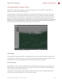
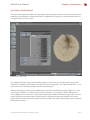
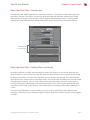
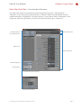
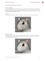
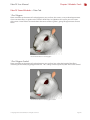
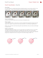
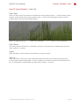
LightWave FiberFX
User Manual
FiberFX User Manual
Contents
Chapter 1 Introduction
What is FiberFX?
How Fibers Are Created
FiberFX Pixel Filter Generated Fibers
Advantages
Disadvantages
Guide Geometry Based Fibers
Advantages
Disadvantages
3D Strand Modeler Geometry ‘Fibers’
Advantages
Disadvantages
How Fibers Are Rendered
Chapter 2 Layout Tools
Introduction
FiberFX Pixel Filter
Adding Fibers to a Model
FiberFX Pixel Filter Interface Overview
Global Controls
Geometry Tab
Instance Tab
Color Tab
Shading Tab
Shadows Tab
Etc. Tab
Editing Strand Guides
FiberFX Node Editor
Chapter 3 Modeler Tools
Introduction
FiberFX Strand Modeler Interface Overview
Global Controls
Fiber Tab
Guides Tab
Random Tab
Gravity Tab
Tools1 Tab
Tools2 Tab
Options Tab
Strand Tool
Strand Maker
© Copyright 1990-2008 NewTek, Inc. All rights reserved.
Page 03
Page 04
Page 05
Page 06
Page 07
Page 08
Page 09
Page 10
Page 11
Page 18
Page 22
Page 25
Page 28
Page 30
Page 31
Page 33
Page 37
Page 38
Page 39
Page 43
Page 46
Page 47
Page 48
Page 49
Page 50
Page 51
Page 52
FiberFX User Manual
Chapter 1 Introduction
What is FiberFX?
FiberFX is a new addition to LightWave 3D 9.5 that allows you to create hair and fur effects on your
models. Whether it’s grass for architectural exteriors, flowing hair on a character, fur on a teddy bear
or any other effect which is largely fibrous looking; FiberFX offers you the flexibility to create many
different looking styles.
FiberFX Hair Example
FiberFX Grass Example
FiberFX consists of 4 separate plugins, one is located in LightWave 3D Layout, the others in LightWave
3D Modeler.
Plugin Name
FiberFX Pixel Filter
FiberFX Strand Modeler
Strand Tool
Strand Maker
Type
Layout
Modeler
Modeler
Modeler
Location In LightWave 3D
‘Image Processing‘ Panel > ‘Add Pixel Filter‘ > ‘FiberFilter‘
‘Setup’ Tab > ‘FiberFX‘ > ‘FiberFX‘
‘Setup’ Tab > ‘FiberFX‘ > ‘Strand Tool‘
‘Setup’ Tab > ‘FiberFX‘ > ‘Strand Maker‘
Each of these tools falls into one of the two main concepts you need to understand while working with
FiberFX; how fibers are created, and how they are rendered.
How Fibers Are Created
Before fibers can be rendered, fiber guides have to be created first. Within FiberFX there are two ways
to create guides, which ultimately allows three approaches to fiber generation. One is to ‘grow’ them
on your model using the ‘FiberFX Pixel Filter’ in LightWave 3D Layout, the second is to model guide
strands using the ‘FiberFX Strand Modeler’ found in LightWave 3D Modeler, which then control the
‘FiberFX Pixel Filter’ generated fibers, and the third is to create fully 3D geometry ‘fibers’ also using the
‘FiberFX Strand Modeler’.
Each of these different fiber creation methods has advantages and disadvantages.
© Copyright 1990-2008 NewTek, Inc. All rights reserved.
Page 3
FiberFX User Manual
Chapter 1 Introduction
FiberFX Pixel Filter Generated Fibers
As already mentioned, these are fibers that are ‘grown’ on your model using the ‘FiberFX Pixel Filter’
plugin, they require no physical geometry guides as these can be created and styled within the plugin.
FiberFX Pixel Filter Generated Fibers
Advantages
The main advantage of ‘FiberFX Pixel Filter’ generated fibers, is that they are much quicker and easier
to setup. Within a few clicks you can have fibers on your model. Your models are also smaller in file
size as there is no geometry needed to be saved.
The other big advantage are the styling tools available for ‘FiberFX Pixel Filter’ fibers. They are much
more intuitive and interactive to use than their modelled counterparts, although modelled fibers can
be controlled much more accurately as they use the LightWave 3D Modeler environment.
Because ‘FiberFX Pixel Filter’ generated fibers can interact with the volumetric system, instancing of
large areas of fibers is possible.
Disadvantages
As already suggested, the main limitation with ‘FiberFX Pixel Filter’ fibers is that they cannot
themselves be animated using LightWave 3D’s dynamics tools. So if you had a character with long hair
and you wanted the hair to move naturally, then you would want to use geometry based fibers.
‘FiberFX Pixel Filter’ generated fibers will move with the underlying mesh however, giving some
impression of movement, but not as realistic.
Because ‘FiberFX Pixel Filter’ generated fibers have no physical 3D volume, they are limited to the finer
looking fibers like hair and fur.
© Copyright 1990-2008 NewTek, Inc. All rights reserved.
Page 4
FiberFX User Manual
Chapter 1 Introduction
Guide Geometry Based Fibers
Although these fibers are also ‘grown’ on your model, they differ in that they are added to guide
strands created by the ‘FiberFX Strand Modeler’ and not on your base object.
Strand guides can be used when modelled as two-point polygon chains in ‘FiberFX Strand Modeler’
which are then used in conjunction with the FiberFX Pixel Filter in LightWave 3D Layout to draw the
fibers directly where the ‘strands’ are located. You can also add more fiber strands around these ‘base
strands’, but there is a limitation which we will go into in the disadvantages section.
FiberFX Pixel Filter Geometry Guided Fibers
Advantages
Because the generated fibers are ‘attached‘ to geometry guide strands, they can be animated like any
other LightWave 3D model using dynamics. As the guide strands are affected by dynamics, the fibers
follow them, which allows more natural movement of the fibers.
Guides strands also have the ability to imported and exported to and from other packages, and so can
be used for styling hair using other third-party tools such as Worley Labs Sasquatch plugin.
Disadvantages
Interactive styling of fibers is limited to basic parameters in the ‘Geometry’ tab in the ‘FiberFX Pixel
Filter’ interface, although it is possible to style the modelled guide strands in ‘FiberFX Strand Modeler’.
If you want to create human hair using a combination of guide strands and ‘FiberFX Pixel Filter’
generated fibers, you will need many guides to ensure good coverage of the head surface, as using the
‘Cluster’ setting (see page XX) to create additional fibers around the guide strands will result in fibers
‘leaving’ the head surface if the ‘Cluster Radius’ setting is too large.
© Copyright 1990-2008 NewTek, Inc. All rights reserved.
Page 5
FiberFX User Manual
Chapter 1 Introduction
3D Strand Modeler Geometry ‘Fibers’
These ‘fibers’ as their name suggests, are actual hard geometry, and are created in LightWave 3D
Modeler using the ‘FiberFX Strand Modeler’.
Geometry fibers can also be given multiple sides so that they have physical 3D volume, at this point
you don’t need to use the FiberFX Pixel Filter to render them as they will be seen by the LightWave
3D renderer like any normal geometry. They can even be made large enough so that you can create
flat areas in which to map images onto. When fibers are created this way, the Strand Modeler also
generates UV maps of the polygons ready to be textured, and corresponding weight maps which could
then be used to animate the polygons even further. Using this method it’s possible to create leaves
using a texture map along with a transparency map, or even feathers.
FiberFX Strand Modeler 3D ‘Fibers’
Advantages
Just like guide based geometry fibers, 3D polygonal ‘fibers’ can be also be animated using dynamics.
Styling of fibers is much more precise as you can use any of Modelers tools to tweak your fibers once
created, or even convert existing geometry into FiberFX ready strands and guides.
Disadvantages
The biggest draw back is the heavy geometry that will be created, especially if you have large areas
of dense fibers, so doing large areas of grass using this method is not really the best option both for
memory, performance and file size reasons.
Setup time is usually longer using this method as there is the extra process of modelling the fibers
ready to be taken into LightWave 3D Layout with your model.
© Copyright 1990-2008 NewTek, Inc. All rights reserved.
Page 6
FiberFX User Manual
Chapter 1 Introduction
How Fibers Are Rendered
Once you have created your fibers (or more specifically, fiber guides) they are ready for rendering. Fiber
rendering is handled by the ‘FiberFX Pixel Filter’ in LightWave 3D Layout, yes, the same plugin that can
also ‘grow’ fibers on your models.
FiberFX Pixel Filter Plugin
The ‘FiberFX Pixel Filter’ takes either the fiber guides you ‘grew’ on your model, or the strand guides
modelled in LightWave 3D Modeler, and renders the fibers using them. The ‘FiberFX Pixel Filter ‘ is also
where you can set surfacing attributes for your rendered fibers.
All fiber rendering is handled inside LightWave 3D Layout by the FiberFX Pixel Filter plugin, this is the
main ‘engine’ of FiberFX. For the most part, fiber rendering is a ‘post-process’ effect, which means
once LightWave 3D has finished it’s part of the rendering, the FiberFX Pixel Filter plugin takes over and
renders the fibers onto the image, in reality FiberFX is working alongside the LightWave 3D render
engine which we’ll talk about more later, but the actual fibers are drawn to the image at the end, hence
the name post-process.
© Copyright 1990-2008 NewTek, Inc. All rights reserved.
Page 7
FiberFX User Manual
Chapter 2 Layout Tools
Fiber Filter Pixel Filter > Introduction
In order to use the ‘FiberFX Pixel Filter’ it needs to be added as a ‘Pixel Filter’ in the ‘Processing’ tab in
the ‘Effects’ window. The ‘Effects’ window can be found under the ‘Windows’ popup menu on the
main interface, or by pressing the hotkey CTRL F8 (Option F8 for Macintosh users). To bring up the
‘FiberFX Pixel Filter’ interface once added, double-click on the ‘FiberFX’ entry in the Pixel Filter list.
Add FiberFX
as a Pixel Filter
Effects Panel > Processing Tab
Fiber Filter Pixel Filter > Adding Fibers to a Model
To quickly add fibers a model, select the object’s name in the ‘Object List‘ on the left, then click the
‘Activate’ button, a ‘tick’ will appear in the ‘On’ column to indicate fibers are now grown on the model.
By default ‘Draw Fibers’ is turned off, to see fibers on your model in the OpenGL view click the blank
space in the ‘Draw’ column next to your object name. You should now see fibers drawn on your model
using the default settings. You can set the limit of how many fiber edges are drawn in the OpenGL
view by changing the ‘Scene Edge Limit’ found under the ‘Etc’ tab. Increasing this number will allow
more fibers to be visible in your OpenGL view at the expense of working speed within LightWave 3D
Layout.
Once you have added fibers to your model, you can now start to modify how they will look when
rendered. In the next part we will go through the ‘FiberFX Pixel Filter’ interface and the various options
available.
© Copyright 1990-2008 NewTek, Inc. All rights reserved.
Page 8
FiberFX User Manual
Chapter 2 Layout Tools
Fiber Filter Pixel Filter > User Interface Overview
The ‘Fiber Filter‘ panel in Layout (found in the ‘Image Processing‘ Panel > ‘Add Pixel Filter‘ >
‘FiberFilter‘) is for creating ‘pixel generated’ fibers. Unlike the ‘FiberFX Strand Modeler’ found in
LightWave Modeler, no geometry is actually created, it is a post-process effect. Although it’s main
usage is for shorter fur type effects, it can also be used to create hair, grass, carpets etc.
Fiber Information
File Operations &
FiberFX Activation
Objects List
Fiber Properties
Global Properties
Guide Editing
FiberFX Fiber Filter Interface
Edit Guides Interface
© Copyright 1990-2008 NewTek, Inc. All rights reserved.
Page 9
FiberFX User Manual
Chapter 2 Layout Tools
Fiber Filter Pixel Filter > Global Controls
There are a number of controls on the main FiberFX interface that allow control over certain global
parameters, as well as some other operations.
Copy / Paste
When you have more than one object with FiberFX applied, you can copy and paste the settings using
these buttons.
Load / Save
Allows you to load and save your FiberFX preset settings to disk. Note any fiber guide styling done
using the ‘Edit Guides’ option is NOT saved in the preset, this information is saved into the scene file.
Activate / Deactivate
Options to turn on / off fiber generation on selected objects.
Show Voxels
FiberFX uses LightWave’s Volumetric system for creating shadows by creating ‘Voxel’ objects along
the fiber length. Each voxel contains the fibers opacity at that point, which means unlike standard
LightWave 3D ‘Shadow Maps’, the shadows from fibers can be opaque or solid where the fiber density
changes. Shadow Maps also require a Spotlight, whereas FiberFX can use any LightWave light, and
only needs to create one shadow structure for all lights in the scene, whereas Shadow Maps require
this process to be completed for each light using shadow maps.
Clicking this option allows you to see shadow’s voxel objects in the main viewport.
Reflections
A global switch to turn on / off reflection of fibers seen in other objects in your scene (fibers do not
reflect within themselves). Currently only the base color of an object can be seen in reflections.
Volume Only
A switch to draw Fibers using LightWave’s Volumetric system instead of using the default post
process pixel filter mode. Volumetric fibers are coarser in appearance, but are able to participate in all
volumetric effects including volumetric lighting.
Edit Guides
Brings up the fiber guide styling tools, which allow you to comb fiber guides directly in the main
viewport using airbrush tools. This is covered in more detail later in the manual.
© Copyright 1990-2008 NewTek, Inc. All rights reserved.
Page 10
FiberFX User Manual
Chapter 2 Layout Tools
Fiber Filter Pixel Filter > Geometry Tab
Max Fiber Density / Fiber Qty
Controls how dense your fibers look on your surface. This setting behaves differently depending on
whether you’re using surface generated fibers or guide driven fibers.
For surface generated fibers ‘Max Fiber Density’ multiplies the number of fibers by the number of
polygons and then distributes them across the entire selected surface area. Small polygons might not
receive any fibers if they haven’t accumulated enough area for a fiber to be placed.
When using geometry guide driven fibers, the ‘Fiber Qty’ is the number of fibers generated around
each guide fiber, each ‘bunch’ of fibers form a wisp, the whole wisp will follow the movement or
animation of the base guide fiber.
Density 2%
Density 15%
Density 60%
Density 100%
Density 200%
Guide Radius
When using geometry guide driven fibers, the radius is how far additional fibers are scattered around
each guide hair. The limitation is that because fibers are not ‘attached’ to the surface, increasing the
radius too far will force fibers off the surface as can be seen in the examples below. This control is
disabled for surface generated fibers as geometry guides are not used.
Qty 32 Rad 2mm
Qty 32 Rad 2cm
Qty 32 Rad 6cm
Qty 32 Rad 12cm
Qty 32 Rad 48cm
Cluster and Cluster Radius
The Cluster setting allows you to add additional fibers around each guide hair, the distance these
additional fibers are away from the guide hair is controlled by the Cluster Radius.
Clstr 1 Rad 3mm
Clstr 4 Rad 3mm
© Copyright 1990-2008 NewTek, Inc. All rights reserved.
Clstr 8 Rad 3mm
Clstr 8 Rad 3cm
Clstr 8 Rad 12cm
Page 11
FiberFX User Manual
Chapter 2 Layout Tools
Fiber Filter Pixel Filter > Geometry Tab
Fiber Smooth
FiberFX draws surface generated fibers as a series of two-point polygon edges, they are not perfectly
smooth splines. When the number of ‘Edges’ setting is greater than 1, you can then use the ‘Fiber
Smooth’ setting to subdivide each edge even further, it works much the same way as ‘Subdivision
Levels’ do on regular LightWave models.
‘Fiber Smooth’ has four levels of subdivision: Level 1=2 Edges, 2=4 Edges,3=8 Edges, 4=16 Edges, these
edge values are how many times EACH edge in the ‘Edges’ setting is divided up into. So 3 ‘Edges’ with
‘Fiber Smooth’ level 2 = 3x4 (16) total edges / fiber.
Fiber Smooth 0
Fiber Smooth 1
Fiber Smooth 2
Fiber Smooth 3
Fiber Smooth 4
Fiber Kink
This ‘Fiber Kink’ setting is only available when ‘Fiber Smooth’ is set to 1 or above. As fiber edges are
subdivided, each newly created edge end point can be perturbed. This creates a kinked look to the
fibers. Because subdivision of fibers is performed just before the edges are drawn, they are not used
in creation of the shadows, as these are created prior to subdivision. As a result, the ‘kinking’ effect will
not be visible in shadows.
Kink 20%
Kink 40%
Kink 60%
Kink 80%
Kink 100%
Fiber Width
Controls how thick or thin fibers appear. Thinner fibers are more transparent and build up density
slower, whereas thick fibers are less transparent and build up density faster. Model scale has an effect
on fiber width, as does the distance to camera.
Fibers further away are smaller in screen space and are more transparent. The percentage is based on
human hair which has been measured at 0.017mm to 0.181mm with blond hair being the thinnest and
black hair the thickest. At 100% width a fiber is calculated using a median value of 0.05mm.
Fiber Width 10%
Fiber Width 25%
© Copyright 1990-2008 NewTek, Inc. All rights reserved.
Fiber Width 50%
Fiber Width 75%
Fiber Width 100%
Page 12
FiberFX User Manual
Chapter 2 Layout Tools
Fiber Filter Pixel Filter > Geometry Tab
Splay
Controls how much fibers can be tilted away from each other. The splay center is calculated from the
centre of each polygon. When using this setting with geometry guide driven fibers, the splay center is
the position of the each guide fiber, all the other fibers tilt away from it.
Splay 20%
Splay 40%
Splay 60%
Splay 80%
Splay 100%
Swirl
Controls how much fibers can be rotated around each other. The splay center is calculated from the
centre of each polygon. When using this setting with geometry guide driven fibers, the swirl center
is the position of the each guide fiber, all the other fibers rotate around it. (‘Swirl Turns’ at 50%). The
Random checkbox makes a random starting rotation offset.
Swirl 20%
Swirl 40%
Swirl 60%
Swirl 80%
Swirl 100%
Swirl Turns
When the ‘Swirl’ setting is above 0%, the amount of turns can be controlled by the ‘Swirl Turns’ setting.
Swirl Turns 20%
Swirl Turns 40%
Swirl Turns 60%
Swirl Turns 80%
Swirl Turns 100%
Tuft
Controls how much fibers can be shorten the further away from the guide center they are. The tuft
center is calculated from the centre of each polygon. When using this setting with geometry guide
driven fibers, the tuft center is the position of the each guide fiber.
Tuft 20%
Tuft 40%
© Copyright 1990-2008 NewTek, Inc. All rights reserved.
Tuft 60%
Tuft 80%
Tuft 100%
Page 13
FiberFX User Manual
Chapter 2 Layout Tools
Fiber Filter Pixel Filter > Geometry Tab
Stray
One fiber in each wisp can be scaled to a larger size, but following the original shape. This creates a
look where just a few strands of hairs poke out from the rest.
Stray 40%
Stray 80%
Stray 120%
Stray 160%
Stray 200%
Random Length
Randomizes the length of the fibers to create a less uniform appearance.
Rand Length 20%
Rand Length 40%
Rand Length 60%
Rand Length 80%
Rand Length 100%
Clump
Fibers can clump together as if sticky or wet. Only fiber within a wisp can clump together.
Clump 20%
Clump 40%
Clump 60%
Clump 80%
Clump 100%
Bump
This effect perturbs the initial fiber direction by simulating a surface bump using the local gradient of
the texture. Similar to ‘Bump Maps’ in the ‘Surface Editor’ in LightWave. This effect needs something in
the texture channel such as a ‘Procedural Texture’ to be visible.
Bump 50%
Bump 150%
© Copyright 1990-2008 NewTek, Inc. All rights reserved.
Bump 300%
Bump 600%
Bump 1200%
Page 14
FiberFX User Manual
Chapter 2 Layout Tools
Fiber Filter Pixel Filter > Geometry Tab
Bump - Root Only
With the ‘Root Only‘ option switched on, bump is calculated from the root only, giving a different look
to how the bump effect is applied.
Bump w/RO 50%
Bump w/RO 150%
Bump w/RO 300%
Bump w/RO 600% Bump w/RO 1200%
Scale
Scales all fibers up or down by the specified amount.
Scale 20%
Scale 60%
Scale 120%
Scale 200%
Scale 400%
Edges
The ‘FiberFX Pixel Filter’ draws fibers as a series of two-point polygon edges, they are not perfectly
smooth splines. You can set the number of edges of your fibers (max 127) using the ‘Edges’ setting.
The higher the number, the smoother your fibers will look.
Edges: 1
Edges: 3
Edges: 6
Gravity
Simulate the effect of gravity on your fibers, pulling them down the more you increase it.
Gravity 20%
Gravity 60%
© Copyright 1990-2008 NewTek, Inc. All rights reserved.
Gravity 120%
Gravity 200%
Gravity 400%
Page 15
FiberFX User Manual
Chapter 2 Layout Tools
Fiber Filter Pixel Filter > Geometry Tab
Gravity - Use Dot
Affects how gravity is calculated. With “Use Dot” inactive fibers on the lowers slope of an object will
hang down like gravity is affecting them. With ”Use Dot” active the fibers will “hug” the surface and
look more like fur.
Gravity w/UD 25%
Gravity w/UD 50%
Gravity w/UD 75% Gravity w/UD 100% Gravity w/UD 150%
Dynamic Gravity
If you have applied some gravity to your fibers, when you rotate your model the fibers will also move
with the model. By turning on ‘Dynamic Gravity’ your fibers will always point in the direction of gravity
even when the object is rotated.
Bias Vmap
A Bias Vmap is an RGB Vmap (vertex map) which tells the fibers which direction to leave the surface.
In order to create a bias map, you must model your fibers in the ‘Strand Modeler’ in LightWave 3D
Modeler (below left image). The directional information of the fibers is automatically stored as a vmap
(below right image) on the model (not the fibers or guides). This is a useful way to control exactly the
direction of fur on your models. The vmap isn’t created until you build the fibers by pressing the ‘Okay’
button in the Strand Modeler. If you only intend to use the bias vmap, you can delete any fiber strands
or guides that you created, as these are no longer needed for the bias map.
Creating a Bias Vmap in the Strand Modeler
© Copyright 1990-2008 NewTek, Inc. All rights reserved.
Resulting Bias Vmap After Creation
Page 16
FiberFX User Manual
Chapter 2 Layout Tools
Fiber Filter Pixel Filter > Geometry Tab
Direction Bias
When a Bias Vmap is selected from the popup menu, you can use this control to influence the amount
the Bias VMap contributes to the direction of the fibers.
Dir’ Bias 0%
Dir’ Bias 50%
Dir’ Bias 100%
Dir’ Bias 200%
Dir’ Bias 300%
Surface
This popup gadget allows you to specify which surface is used to grow fibers on. The default is ‘All’
which will grow fibers on every surface of the selected model, when you select a surface, fibers are
grown only on that surface.
If you need to isolate different areas of the model with the same surface name, you can use either
weight or image maps (found under the ‘T’ button to the right of every parameter that supports them)
to further control the look of your fibers.
© Copyright 1990-2008 NewTek, Inc. All rights reserved.
Page 17
FiberFX User Manual
Chapter 2 Layout Tools
Fiber Filter Pixel Filter > Instance Tab
How Instancing Works
FiberFX utilizes LightWave’s volumetric system in order to achieve instancing. To activate the
instancing controls within FiberFX you must first add a ‘Particle Emitter’ to your object. This step MUST
be done BEFORE you add FiberFX to your scene.
Instancing also only works with ‘Volumetric’ fibers, so on the main FiberFX interface, makes sure you
switch ‘Volume Only’ on.
To add a particle emitter to you object. First select the object, then bring up the ‘properties’ panel
(keyboard shortcut ‘p’). Under the ‘Dynamics’ tab there is a popup menu called ‘Add Dynamic’, click
that and select ‘Emitter’ from the menu. Next double click the ‘FX Emitter’ entry to bring up the
properties.
Adding a Particle Emitter to an Object
When using the particle system for placement of fibers, you must remember that fibers will be subject
to the properties and behavior of particles. To avoid having your fibers disappear over time and
to ensure they are all visible at the beginning of your animation, set the ‘Birth Rate’ to the number
of ‘instances’ you require, set the ‘Generate By’ option to ‘Frame’, then set the ‘Particle Limit’ to the
same value as the ‘Birth rate’, these settings can be found under the ‘Generator’ tab. Next, under the
‘Particle’ tab, make sure you set the ‘Life Time (Frame)’ setting to 0, this makes the particles live forever.
This will set the number of particles to appear all at once at the start of your animation, stop generating
(as the particle limit is reached on the first frame) and last until the end of your animation.
Finally, set the ‘Nozzle’ type on the ‘Generator’ tab to one that best suits the distribution you’re after.
© Copyright 1990-2008 NewTek, Inc. All rights reserved.
Page 18
FiberFX User Manual
Chapter 2 Layout Tools
Fiber Filter Pixel Filter > Instance Tab
Setting Up Instancing
Once the particles that will drive the fiber instances are setup, you’re ready to setup FiberFX to take
advantage of them. On the ‘Instance’ tab, make sure ‘Volume Only‘ is switched on, then select the
particle emitter you setup on your object from the ‘Particle System’ popup menu.
Activating FiberFX Instancing
© Copyright 1990-2008 NewTek, Inc. All rights reserved.
Page 19
FiberFX User Manual
Chapter 2 Layout Tools
Fiber Filter Pixel Filter > Instance Tab
Once activated, FiberFX will take whatever fiber setup you have and ‘clone’ it to each particle location.
In the example below we want to use instancing to create a number of grass clumps across the ground.
If we applied FiberFX to the whole ground surface it would be cloned many times over itself. This is
not what we want as can be seen in the image below.
FiberFX Instancing Incorrectly Applied
What we need to do is setup a smaller patch of grass by renaming just a few polygons on the ground
plane, we will then use this smaller surface to setup our fibers on. The rest of the ground plane needs
to be named differently from the ‘grass’ surface. In the image below you can see the fibers setup on
the surface BEFORE instancing is applied.
FiberFX Grass Fiber Setup Before Instancing
© Copyright 1990-2008 NewTek, Inc. All rights reserved.
Page 20
FiberFX User Manual
Chapter 2 Layout Tools
Fiber Filter Pixel Filter > Instance Tab
Once instancing is activated this is what we now see.
FiberFX Grass Fiber Setup After Instancing
Here are some examples showing what can be achieved using this method.
© Copyright 1990-2008 NewTek, Inc. All rights reserved.
Page 21
FiberFX User Manual
Chapter 2 Layout Tools
Fiber Filter Pixel Filter > Color Tab
This tab is where you control the base color of your rendered fibers. There are two main modes for
coloring fibers, Mixed (default) and Textured.
Color Mode - Mixed
When this mode is selected you can blend between two fiber colors (each with a different root and tip
color). You can also set the amount each color influences the overall fiber color. At 0% ‘Base / Tip Color
1’ will be the predominant color, at 100% ‘Base / Tip Color 2’ will be the predominant color. In this
example we have the first color set to a reddish color, and the second to a blue color.
Color Mix 0%
Color Mix 25%
Color Mix 50%
Color Mix 75%
Color Mix 100%
Blend (Mixed Color Mode)
When ‘Blend’ is checked, the colors values themselves are actually mixed, as oppose to just the amount
of fibers using those colors, you can see this best in the 50% setting below when compared without.
With Blend 0%
With Blend 25%
With Blend 50%
With Blend 75%
With Blend 100%
Highlight (Mixed Color Mode)
This setting randomizes fiber shading by choosing lighter and darker values based on the original
base colors used. The percentage determines how much different the light or dark values are from the
original colors.
Highlight 0%
Highlight 50%
© Copyright 1990-2008 NewTek, Inc. All rights reserved.
Highlight 150%
Highlight 200%
Highlight 400%
Page 22
FiberFX User Manual
Chapter 2 Layout Tools
Fiber Filter Pixel Filter > Color Tab
Color Mode - Textured
When this mode is selected you can use either the color picker to select a simple base color. Unlike
‘Mixed’ color mode, all your fibers will be the same color. However, you can now also use the standard
LightWave 3D texture editor to color your fibers, this offers many options for texturing your fibers.
Plain Color
Texture Map
Fiber U Gradient
Fiber U Gradient
‘Fiber U’ allows you to control a particular settings value as it travels along the fiber length from root to
tip. In the example below we are controlling the fiber colour of some hair from blue at the root to red
at the tip. The results of which can seen in the above right example.
Fiber U: 0.5
Fiber U: 0.0
Fiber U: 1.0
Fiber U Gradient
Highlight (Textured Color Mode)
The ‘Highlight‘ setting is common to both color modes, and works the same in ‘Textured’ color mode
as it does with ‘Mixed’ color mode.
Highlight 0%
Highlight 50%
© Copyright 1990-2008 NewTek, Inc. All rights reserved.
Highlight 150%
Highlight 200%
Highlight 400%
Page 23
FiberFX User Manual
Chapter 2 Layout Tools
Fiber Filter Pixel Filter > Color Tab
Color Evaluation
There are two methods for ‘Color Evaluation’ in the ‘Color’ tab: ‘Interpolated Color’ and ‘Per Pixel Color’.
Interpolated Color
Interpolated evaluation is slightly faster than per pixel, but can only evaluate color changes at edge
end points, and then blends between them along the fiber.
The limitation of this mode occurs if you want many color changes along a fiber without having
enough edge end points for FiberFX to evaluate the color on. So if you had 4 color changes on a
gradient along the fiber length, but only 1 edge, you will only see 2 color changes, one change for each
end point on the edge.
Per Pixel Color
Although slightly slower than interpolated mode, it can evaluate color changes anywhere along the
fiber length, regardless if there is an edge end point there or not.
This means that using ‘Per Pixel Color’ evaluation would show all the color changes along the length
even if you didn’t have enough edge end points to ‘change colour on’.
The differences are best best shown in the examples below. There are 9 color changes along the length
of the fiber using a gradient (locations 0, 12.5, 25, 37.5, 50, 62.5, 75, 87.5 and 100%) fiber smoothing is
off and edges have been set to 1, which means each fiber has a total of 2 edge end points.
As you can see, the ‘Interpolated Color’ evaluation only shows two of those color changes along the
length of the fiber. Whereas ‘Per Pixel Color’ shows all 9 color changes.
Interpolated Color: 1 edge, 2 colors evaluated
© Copyright 1990-2008 NewTek, Inc. All rights reserved.
Per Pixel Color: 1 edge, all 9 colors evaluated
Page 24
FiberFX User Manual
Chapter 2 Layout Tools
Fiber Filter Pixel Filter > Shading Tab
This tab contains all the surfacing parameters for your fibers, much of the settings work in the same
way they do in the standard LightWave 3D ‘Surface Editor’.
Diffuse
Determines how much your fibers react to the diffuse setting on lights. Essentially simulating the
scattering of light over the fiber surface (not to be confused with sub-surface scattering). The higher
the percentage the brighter overall your fibers will look.
Diffuse 10%
Diffuse 50%
Diffuse 100%
Diffuse 200%
Diffuse 400%
Specular / Specular Color
Controls how much your fibers will react to specular settings on lights. As with other specularity
settings in LightWave this is the ‘simulation’ of lights being reflected on your fibers. Higher values will
increase the intensity of this effect. You can also specify the color of the specular highlights using the
‘Specular Color’ picker.
Specular 10%
Specular 50%
Specular 100%
Specular 200%
Specular 400%
Gloss
In order to see the effect of the gloss setting, you must have ‘Specular’ above 0%. Much like the gloss
setting in the surface editor, the gloss setting controls the spread of the specular highlights on your
fibers. This setting works slightly differently however. At 0% gloss is off, once over 0%, low values
result in a broader spread of your specular highlights, as the percentage goes higher the spread then
becomes narrower. In the examples below, a specular value of 200% was also used.
Gloss 5%
Gloss 10%
© Copyright 1990-2008 NewTek, Inc. All rights reserved.
Gloss 30%
Gloss 60%
Gloss 90%
Page 25
FiberFX User Manual
Chapter 2 Layout Tools
Fiber Filter Pixel Filter > Shading Tab
Luminosity
Another similar acting surface editor setting. Luminosity controls how ‘bright’ or self-illuminating your
fibers look, higher percentages mean brighter fibers. They don’t actually emit any light though.
In the examples below ‘Diffuse’ was set to 75% and ‘Specular’ 100% to better see the effect.
Luminosity 10%
Luminosity 50%
Luminosity 100%
Luminosity 200%
Luminosity 400%
Ambient
Controls how much ambient light affects your fibers. In order to see any changes, your scene must
have ‘Ambient Intensity’ in your ‘Light Properties’ panel above 0%. Higher percentages mean your
fibers receive more ambient light, and therefore look brighter as a result. In the examples below
‘Diffuse’ was set to 50%, ‘Specular’ 100% and ‘Ambient Intensity’ 50% to better see the effect.
Ambient 10%
Ambient 50%
Ambient 100%
Ambient 200%
Ambient 400%
Tip Transparency
‘Tip Transparency’ controls at what percentage along your fibers length (starting from the root) your
fibers start to have transparency down to 0% at the ends, effectively ‘fading them out’. 0% means your
fibers have no transparency, and so will appear solid right to the tips. 50% would mean that at 50%
along your fibers, they start to ‘fade out’ until they reach 100% transparent at the tips. Makes hair look
thick (0%) or fine and fly-away (100%). In the examples below ‘Diffuse’ was set to 75% and ‘Specular’
100% to better see the effect.
Tip Trans 0%
Tip Trans 25%
© Copyright 1990-2008 NewTek, Inc. All rights reserved.
Tip Trans 50%
Tip Trans 75%
Tip Trans 100%
Page 26
FiberFX User Manual
Chapter 2 Layout Tools
Fiber Filter Pixel Filter > Shading Tab
Translucency
Translucency is only really apparent with lights placed behind the subject. Higher translucency
settings give the impression of more light passing through the fibers making them lighter. This effects
the outer edges of your fibers more than the main body. In the examples below ‘Diffuse’ was set to
75% and ‘Specular’ 100% to better see the effect (more noticeable down the right hand side).
Translucency 10%
Translucency 50% Translucency 100% Translucency 200% Translucency 400%
Cuticle Tilt
This setting only works when the ‘Specular’ setting is above 0% as it controls the position of the
specular highlight on the fibers. At 0% the specular highlight is where it naturally lies when light
hits it, negative values pull the highlights towards the roots, whereas higher, positive values push
the highlights away from the roots and towards the tips. Think of it as a ‘manual override’ for where
specular highlights hit your fibers. In the examples below ‘Diffuse’ was set to 75%, ‘Specular’ 100% and
‘Gloss’ 5% to better see the effect.
Cuticle Tilt -100%
Cuticle Tilt -50%
Cuticle Tilt 0%
Cuticle Tilt 50%
Cuticle Tilt 100%
Secondary Gloss / Cuticle Tilt 2
Simulates the secondary ‘gloss’ or ‘shine’ fibers display (mainly hair) when light is bounced around
inside the fibers as a result of being naturally translucent (not linked to ‘Translucency’ setting). Works
the same way as the first ‘Gloss’ setting. Cuticle Tilt 2 controls the position of the secondary gloss in
the same way ‘Cuticle Tilt’ controls the first ‘Gloss’ setting.
Sec’dry Gloss 5%
Sec’dry Gloss 10%
Cuticle Tilt2 -100% Cuticle Tilt2 -50%
© Copyright 1990-2008 NewTek, Inc. All rights reserved.
Sec’dry Gloss 30%
Sec’dry Gloss 60%
Sec’dry Gloss 90%
Cuticle Tilt2 0%
Cuticle Tilt2 50%
Cuticle Tilt2 100%
Page 27
FiberFX User Manual
Chapter 2 Layout Tools
Fiber Filter Pixel Filter > Shadows Tab
This tab contains the controls for tailoring the look of the shadowing of your fibers.
FiberFX uses LightWave’s Volumetric system for creating shadows by creating ‘Voxel’ objects along
the fiber length. Each voxel contains the fibers opacity at that point, which means unlike standard
LightWave 3D ‘Shadow Maps’, the shadows from fibers can be opaque or solid where the fiber density
changes. Shadow Maps also require a Spotlight, whereas FiberFX can use any LightWave light, and
only needs to create one shadow structure for all lights in the scene, whereas Shadow Maps require
this process to be completed for each light using shadow maps.
You can view the voxels used to create the volumetric shadow objects in Layout by clicking the “View
Voxels” button.
To globally toggle shadows on / off, use the ‘Volumetric Shadows’ button.
Self Shadow
Sets the amount of fiber self shadowing. Higher values result in darker shadows, giving the
appearance of thicker looking fibers, whereas lower values result in lighter shadows giving the
appearance of thinner fibers. In the examples below ‘Cast Shadows’ was set to 15%. It’s also worth
noting that the greater your ‘Max Fiber Density / Fiber Qty’ setting on the ‘Geometry’ tab, the more
dense self shadowing will appear, as there are more fibers to cast shadows.
Self Shadow 0%
Self Shadow 15%
Self Shadow 30%
Self Shadow 60%
Self Shadow 100%
Cast Shadow
Sets the density of shadows cast by fibers onto other objects. Higher values result in darker shadows,
lower values result in lighter shadows. In the examples below ‘Self Shadow’ was set to 15%. The
shadow you see when ‘Cast Shadow’ is at 0% is from the object the fibers are attached to, not the
fibers themselves.
Cast Shadow 0%
Cast Shadow 15%
© Copyright 1990-2008 NewTek, Inc. All rights reserved.
Cast Shadow 30%
Cast Shadow 60% Cast Shadow 100%
Page 28
FiberFX User Manual
Chapter 2 Layout Tools
Fiber Filter Pixel Filter > Shadows Tab
Shadow Depth
This controls the shadow quality. Shadows are created by subdividing the fiber object into many small
voxel boxes. The density of each little box is measured and used to create the shadows. Lower values
result in coarser, less accurate shadows, but will render faster. Higher values mean smoother, more
accurate shadows, but slower rendering. A value of 16 works best for most setups.
Shadow Depth 2
Shadow Depth 4
Shadow Depth 8
Shadow Depth 12
Shadow Depth 16
Multisample
Creates multiple shadow samples randomized on a hemisphere about the Light direction. This
smooths out shadows at the expense of more shadow rays.
Shadow Type
There are three shadow types for fibers in FiberFX. ‘Interpolated’, ‘Ray Trace’ and ‘Point Sample’.
Interpolated Shadows
Ray Traced Shadows
These are the fastest shadows.
Fully traced, but slowest.
Point Sample Shadows
Better quality than Interpolated,
but slower
Sample Radius
When ‘Shadow Type’ is set to ‘Point Sample’, the ‘Sample Radius’ option becomes available. The larger
the sample radius, the smoother but less accurate point sampled shadows become.
Sample Radius 1
Sample Radius 2
© Copyright 1990-2008 NewTek, Inc. All rights reserved.
Sample Radius 3
Sample Radius 4
Page 29
FiberFX User Manual
Chapter 2 Layout Tools
Fiber Filter Pixel Filter > Etc Tab
The ‘Etc’ tab contains preferences for the FiberFX plugin, as well as buffer saving options.
Cull Angle
To speed up the OpenGL display of fibers, this setting eliminates fibers early in the drawing stage that
would be behind the object and not be drawn. At 100% fibers beyond the objects profile edge will be
culled, at 0% no fibers are culled.
Fade Angle
This is the angle the fibers fade out over. Tweak this value to have long back facing fibers fade
gradually instead of just disappearing from the OpenGL view.
Scene Edge Limit
Sets the maximum number of fiber edges drawn in the OpenGL view. The higher the number the
more fibers will be visible at the expense of slower OpenGL responsiveness.
World
Turning this option on gathers fiber coordinates in world space and not in relation to the object parent
coordinates. Typically you would have this setting off, but if you are using LightWave Dynamics to
animate fibers, you need to turn this on and unparent to gather the coordinates correctly.
Before Volume
Runs the pixel filter and sets the depth buffer before any volumetric plug-ins. This allows volumetric
effects like LightWave’s HyperVoxels to contribute to the FiberFX depth buffer.
Save RGBA
Saves the RGBA buffers to a separate file. When this item is active the fibers will not be drawn into the
image filter buffer. Make sure you select a file format capable of saving in RGBA (RGB + Alpha) or you
will lose the alpha channel.
Save Z
Saves the depth buffer information in separate floating point buffer. When this is selected, Z buffer
values will not be written to the image filter buffer. Make sure you select a file format capable of
saving data in floating points.
© Copyright 1990-2008 NewTek, Inc. All rights reserved.
Page 30
FiberFX User Manual
Chapter 2 Layout Tools
Fiber Filter Pixel Filter > Editing Strand Guides
FiberFX allows airbrush like styling of fiber guides directly within the LightWave Layout OpenGL
viewport. These tools are very intuitive to use, and allow more natural styling of fibers than using just
the basic parameters found in the ‘Geometry’ tab.
To bring up the styling tools click the ‘Edit Guides’ button in the lower left corner of the main FiberFX
interface. Once clicked, the main FiberFX interface will be hidden and you will be presented with ‘Edit
Strands’ dialog box.
The fibers also become hidden and you will see the guides that control them instead, these are what
you will be styling. It’s worth noting at this point that when you begin styling your guides the ‘Edges’
setting in the ‘Geometry’ tab will become locked, so either make sure you have edges set to what you
want before styling, or save a ‘before styling’ version of the scene to preserve the ability to edit edges.
FiberFX Strand Guide Editing in Layout
© Copyright 1990-2008 NewTek, Inc. All rights reserved.
Page 31
FiberFX User Manual
Chapter 2 Layout Tools
Fiber Filter Pixel Filter > Editing Strand Guides
Brush Type - Push
Push mode is similar to combing, guides can be dragged in the direction you move the mouse.
Brush Type - Scale
Scale mode will increase the length of the guides, if you use the right mouse button while dragging
the guides will decrease in length.
Brush Type - Straighten
This mode will straighten the guides based on the ‘normal’ direction from where the guide started.
Brush Type - Single
Single mode allows the ‘pushing’ of individual guides, useful for tweaking any stray guides that may
have occurred as a result of styling guides.
Brush Mode - Radius
Uses airbrush like manipulation of the ‘Brush Types’, anything within the brush circle is edited, except
on ‘Single’ where only one guide will be moved.
Brush Mode - Global
Every guide on the object will be edited equally, allows en-masse editing.
Brush Mode - Surface Hug
Works similar to ‘Radius’ mode, but follows the nearest surface on the object.
Brush Radius
Sets the working size of the brush when ‘Brush Type’ is set to ‘Radius’.
Brush Strength
Sets the power of the brush, smaller values allow finer tweaks, larger values edit guides much more
aggressively. Entering negative values ‘invert’ the direction of the ‘Scale’ brush type without needing
to use the right mouse button while brushing.
Undo / Redo
Allows you to undo / redo brushing strokes whilst within the guide editing interface.
Reset
Resets all changes made going back to when you last opened the ‘Edit Guides’ interface.
Reset Default
Completely resets ALL styling changes, use with caution, as you cannot undo this change.
© Copyright 1990-2008 NewTek, Inc. All rights reserved.
Page 32
FiberFX User Manual
Chapter 2 Layout Tools
Fiber Filter Pixel Filter > Node Editor
The Node controls for FiberFX are more advanced that the basic parameters found on the ‘Geometry’
tab, and so, have been deliberately left until the end of this section before introducing them. Having
an understanding of the basics in FiberFX will hopefully help making node editor concepts easier.
An example FiberFX node flow
Node Editor Usage
The node editor in FiberFX allows you to control the appearance of the fiber ‘geometry’ styling, as well
as the base color of fibers. Once opened you are presented with a standard LightWave 3D Node Editor.
The FiberFX ‘root node’ has 4 inputs that you can control: Vector, Amplitude, Length and Color. When
anything is plugged into the ‘Color’ input, the Node Editor will override that parameter, but the Vector
and Amplitude inputs allow blending of any calculations within the Node Editor and any settings
changed on the ‘Geometry’ tab
Double-clicking on the FiberFX root node will display two parameters for how the Node Editor will
calculate the resulting direction.
FiberFX Root Node & Properties
‘Local Displacement’ orients the displacement to be performed along the underlying polygons normal,
this mode is useful for creating swirls, as the ripples radiate down the fiber. Turning it off uses object
space displacement, use this mode for things like fields of waving grass.
‘Nodal First’ changes the order that the nodes and other effects are evaluated, for instance, if you have
gravity set to make the fibers droop, it is possible to set the nodes to override the effect of the gravity.
The default setting for nodes first will prevent this.
© Copyright 1990-2008 NewTek, Inc. All rights reserved.
Page 33
FiberFX User Manual
Chapter 2 Layout Tools
Fiber Filter Pixel Filter > Node Editor
FiberInfoNode
The ‘FiberInfoNode’ allows access to fiber edge information, which you can then use along with regular
nodes to modify them, this allows you to create more custom styling of fibers not available by using
the standard controls on the ‘Geometry’ tab on the main FiberFX interface. Double-clicking on the
‘FiberInfoNode’ allows you to select which FiberFX object to gather the data from.
FiberFX FiberInfoNode & Properties
Fiber U
The position of the evaluation down the length of the fiber. Starting from 0.0 at the root to 1.0 at the
tip. Use this as an input to opacity on a node to control effect strength down the length.
Poly Normal
The normal vector coordinates of the underlying polygon that the fiber is growing from.
Poly Center Position
The center position of the underlying polygon that the fiber is growing from.
Offset
The offset position of the fiber currently being evaluated.
Fiber Tangent
The normal vector of the edge currently being evaluated.
Fiber Base Position
Position in local coordinates of the base of each fiber currently being evaluated.
Fiber Edge Position
Start position in local coordinates of the edge currently being evaluated.
Fiber Number
Returns the fiber number that is being evaluated
© Copyright 1990-2008 NewTek, Inc. All rights reserved.
Page 34
FiberFX User Manual
Chapter 2 Layout Tools
Fiber Filter Pixel Filter > Node Editor
Offset Amt (Amount)
The offset of each added fiber from the parent ‘wisp’ or guide fiber.
Cluster
Returns the fiber’s Cluster number. Use it to determine if a clustered fiber is being evaluated.
To Up Right
Transform from polygon coordinates to up right.
To Up Up
Transform from polygon coordinates to up up.
To Up Forward
Transform from polygon coordinates to up foward.
From Up Right
Transform from up right to polygon coordinates.
From Up Up
Transform from up up to polygon coordinates.
From Up Forward
Transform from up forward to polygon coordinates.
FiberFX Root Node
FiberFX Root Node & Properties
Color
Changes the color of the fibers. Use a Fiber U input on a gradient to change colors based on the
position along the fiber length.
Amplitude
Use this input to change the amount of amplitude of the Vector input’s perturbation. Without any
amplitude input, 100% of the Vector input will be used, often resulting in harsh changes of direction.
Vector
Controls the direction of the fiber edge vector. The old and new fiber directions are interpolated
together by the Amplitude amount.
Length
Controls the length of the fiber.
© Copyright 1990-2008 NewTek, Inc. All rights reserved.
Page 35
FiberFX User Manual
Chapter 2 Layout Tools
Fiber Filter Pixel Filter > Node Editor
Example Node Flow
Here is an example of what can be achieved using the node editor.
Faked Fiber Dynamics
This very simple node flow gives the illusion of dynamics on the fibers.
The scene has a simple sphere object with fibers grown on the surface and a NULL object.
Fake Dynamics Node Flow
The fibers vector direction is controlled by subtracting the NULL’s world position from the sphere’s
world position. The amount of the resulting vector direction is then controlled by the Fiber U position,
so that at the root of the fiber the strength is low, and higher at the tip, this gives the illusion of ‘fading
out’ of the movement.
In Layout, the sphere and NULL object are hand animated to move the fibers in the general direction
they would move in reality to simulate dynamic movement. Clearly this is not as accurate as using
actual LightWave Dynamics, but it’s a neat solution to animating ‘Pixel Generated’ fibers that usually
can’t be animated using LightWave Dynamics.
The result using the node editor to simulate dynamic movement of fibers
© Copyright 1990-2008 NewTek, Inc. All rights reserved.
Page 36
FiberFX User Manual
Chapter 3 Modeler Tools
FiberFX Strand Modeler > Introduction
There are a number of tools available in LightWave 3D Modeler for FiberFX. These tools not only
allow you to build 2-point poly chain fiber guides for use with the FiberFX Pixel Filter plugin in Layout,
but the creation of full 3D fiber geometry, Vertex Bias maps for controlling fiber direction and autocreation of UV maps for 3D fibers.
FiberFX Strand Modeler > Interface Overview
The ‘Strand Modeler’ is the main part of FiberFX inside LightWave Modeler. It can be found under the
‘Setup’ tab > ‘Fiber FX’ title. When opened the Strand Modeler interface looks like this:
Tool Property Tabs
View Settings
Viewport
Settings File Operations
& Viewport Controls
Tool Properties
Surface Selection
& Fiber Operations
FiberFX Strand Modeler Interface
Fiber Information
Viewport Hotkeys
The OpenGL viewport window supports many of the same hotkeys as LightWave 3D. Holding down
the Alt key while dragging in the viewport rotates the view, Alt + Ctrl zooms and Alt + Shift pans the
view.
The ‘a’ key auto fits and centers the object in view. The numerical keys 1 - 6 changes the viewport to
show front, back, top, bottom, right and left views respectively.
© Copyright 1990-2008 NewTek, Inc. All rights reserved.
Page 37
FiberFX User Manual
Chapter 3 Modeler Tools
FiberFX Strand Modeler > Global Controls
Surface Selection & Controls
In the lower left hand corner, you can select which surface on your model to grow your fibers on using
the popup menu. You are not limited to just one surface, selecting a different surface name allows you
to grow fibers with different settings on each surface in one fiber modelling session.
Once you have selected your surface, click the ‘Grow’ button, this will then add fibers to the selected
surface using the current settings. Switching between surfaces allows you to edit the fibers
parameters for that particular surface.
You can also click the ‘Hide’ button should you need to clean up the view while working on a particular
part of your model.
FiberFX Strand Modeler showing fibers with different parameters grown on an object.
Load / Save
If you want to save your fiber editing session for later, you can save and load using these controls (you
will need to save each surface setting if you have more than one). Note, any guides you’ve added will
not be saved. To store guides you must click the ‘Okay’ button to complete the session. Fibers will be
created along with the guides (each in different layers). To recall your session you must first load the
settings, then load the guides using the ‘Add Guides’ popup menu found under the ‘Guides’ tab.
© Copyright 1990-2008 NewTek, Inc. All rights reserved.
Page 38
FiberFX User Manual
Chapter 3 Modeler Tools
FiberFX Strand Modeler > Fiber Tab
Fiber Distribution
There are two methods for distributing fibers over your models surface, ‘By Area’ and ‘1 Per Polygon’.
Both of these methods also have a ‘Scaled’ option whereby the size of the underlying polygon is taken
into consideration, you can adjust this compensation by adjusting the ‘Area Scale’ property. This gives
a total of four actual distribution methods.
By Area
The number are fibers in the ‘Fiber Qty’ setting are scattered across the whole surface randomly.
Fiber Distribution ‘By Area‘
By Area Scaled
The number are fibers in the ‘Fiber Qty’ setting are scattered across the whole surface randomly but
scales the length of the fibers according to the underlying polygon area size. This scaling can be
adjusted by the ‘Area Scale’ control.
Fiber Distribution ‘By Area Scaled‘
© Copyright 1990-2008 NewTek, Inc. All rights reserved.
Page 39
FiberFX User Manual
Chapter 3 Modeler Tools
FiberFX Strand Modeler > Fiber Tab
1 Per Polygon
Places one fiber at the center of each polygon on your surface, this creates a very ordered appearance.
If you use these fibers as guides in the ‘FiberFX Pixel Filter’ in LightWave 3D Layout, you can create
many more ‘virtual’ fibers clustered about the centre of these ‘guides’, giving the appearance of more
fibers.
Fiber Distribution ‘1 Per Polygon‘
1 Per Polygon Scaled
Places one fiber at the center of each polygon on your surface, but scales the length of the fibers
according to the underlying polygon area size. This scaling can be adjusted by the ‘Area Scale’ control.
Fiber Distribution ‘1 Per Polygon Scaled‘
© Copyright 1990-2008 NewTek, Inc. All rights reserved.
Page 40
FiberFX User Manual
Chapter 3 Modeler Tools
FiberFX Strand Modeler > Fiber Tab
Area Scale
This setting becomes available when the fiber distribution method is set to ‘By Area Scaled‘ or ‘1 Per
Polygon Scaled‘. It adjusts the percentage of scaling from the largest to the smallest polygons.
Area Scale 0%
Area Scale 25%
Area Scale 50%
Area Scale 75%
Area Scale 100%
Fiber Qty (Quantity)
Determines the number of fibers to be used in ‘By Area’ distribution mode.
Fiber Length
Set the length of the fibers. If ‘Area Scale’ is active this would be the length of the polygons with the
largest area. Length is measured from root to tip with the fiber in an absolutely straight position.
Effects such as Curl, Kink, and Gravity change the shape of the fiber, and may cause the overall length
to appear shorter.
Edge Qty (Quantity)
The number of edges on each fiber strand. The more edges the smoother the strand. If you render
your fibers using the ‘FiberFX Pixel Filter’ in LightWave 3D Layout, fiber strands can be further
subdivided by using the ‘Fiber Smooth’ setting. If required, you can cover an object with single point
polygons by setting the ‘Fiber Sides’ setting to 0. The maximum edges per fiber is 127.
Edges: 1
Edges: 3
Fiber Sides 1
© Copyright 1990-2008 NewTek, Inc. All rights reserved.
Fiber Sides 2
Edges: 6
Fiber Sides 3
Page 41
FiberFX User Manual
Chapter 3 Modeler Tools
FiberFX Strand Modeler > Fiber Tab
Fiber Sides
Fibers can more sides if you intent to use FiberFX for creating fully 3D ‘fibers’. 1 side will create 2-point
polygon strands which can be used as guide strands. 2 sides creates flat polygon ‘blades’, and any
number above 2 will create full 3D fiber objects.
Sides 1: 2-point poly chains
Sides 2: Flat 2D blades
Sides 3+: Full 3D geometry
Fiber Radius
The setting controls the thickness of the fiber at the base. It only becomes available when the ‘Fiber
Sides’ setting is 1 or above.
Angle
Multi-sided fibers can be rotated around their axis using this control.
Taper %
Multi-sided fibers can be set to taper along their length, from root to tip. Higher percentages will
create sharper pointier looking fibers. If set to a negative value, fibers can be made to have blunt flat
tips. It only becomes available when the ‘Fiber Sides’ setting is 1 or above.
© Copyright 1990-2008 NewTek, Inc. All rights reserved.
Page 42
FiberFX User Manual
Chapter 3 Modeler Tools
FiberFX Strand Modeler > Guides Tab
Spline Type
Changes the spline calculation method for all splines (you can toggle between them).
‘Interpolating’ splines pass through each knot of the guide. Whereas ‘Approximating’ splines act more
like Bezier splines. ‘Interpolating’ splines can be bent tighter, ‘Approximating’ splines are smoother.
‘Interpolating’ Splines
‘Approximating’ Splines
Add Guide
To place a guide on your model to control the fibers, click this button (or press the hotkey ‘g’) then
select a polygon on your model that will serve as the place holder for your guide. You can only place
one guide per polygon.
To add many guides in one go, use the ‘Grow’ button to add fibers to your model and set the ‘Fiber
Qty’ setting to the number of guides you require. Then click the ‘Okay’ button to commit your settings.
Run the Strand Modeler again and use the ‘Add Guides’ popup menu selecting the layer that contains
the fibers you just created. These will then load up as guides and not fibers. Or you can select ‘Current
Fibers’ option which is a much quicker way of doing the same operation.
Scale (Guides)
Scales the length of the selected guides, this will also scale the length of any fibers they are controlling
as a result.
Del Guide (Delete Guide)
To delete a guide hold down the ‘Shift’ key and drag a box selection using your mouse over the guide
you wish to delete (normal left mouse clicking doesn’t select a guide as this is how you move guide
knots, not select them). You can continue to use this same method to select multiple guides. When a
guide is selected the last knot will be highlighted white. You can now click the ‘Del Guide’ button to
remove the selected guides.
© Copyright 1990-2008 NewTek, Inc. All rights reserved.
Page 43
FiberFX User Manual
Chapter 3 Modeler Tools
FiberFX Strand Modeler > Guides Tab
Add Node (Guide Knot)
To add a new node (or knot) click this button, It will add a node / knot to ALL guides. Currently all
guides must have a uniform node / knot count.
Del Node (Guide Knot)
Clicking this button will delete the last node or knot from ALL guides.
Add Guides (Load Guides)
You can add or load guides in a number of ways using this popup menu. You can load guides
previously saved on layers in your object. 2-point polygon fiber chains can also be loaded back in as
guides, and not fibers.
Guides can be created from fibers currently growing on the surface. Note: guides created using this
method take on the exact shape of your current fibers, so any styling done to them will be reflected in
the shape of the guides.
You can also create guides based every polygon on the currently selected surface - guides will be
created matching each polygons ‘normal’ vector. Or you can create guides based on every single point
on the currently selected surface, again these will be created using the point normal vector.
Save Guides
Saves the current guide set to the next available layer in Modeler.
Select Node (Knot)
This popup allows you to select either the First / Last node or knot on every guide (it selects all knots
on every guide because any deletion of knots must be equal on all guides). You can also use Previous /
Next to step through intermediate knots, or use the ‘None’ option to deselect.
Clear Guides
Clear all guides on the surface.
IK Guides
By default, when manipulating guides using the mouse, they use an IK (Inverse Kinematic) method of
handling the guide chains which keeps all knots at an equal distance apart. If you wish to override this
method, uncheck the ‘IK’ option. You will now be able to move knots anywhere you desire.
© Copyright 1990-2008 NewTek, Inc. All rights reserved.
Page 44
FiberFX User Manual
Chapter 3 Modeler Tools
FiberFX Strand Modeler > Guides Tab
Interpolation
Guides have several ‘Interpolation’ methods available to them to further refine their area of influence
on the fibers. Clicking the root knot on a guide changes its interpolation method (the color also
changes to show which mode you’re in) and if applicable the radius of influence the interpolation has.
Sharp Wide
Interpolate Wide
Radius Sharp
Radius Sharp w/fx
Radius Interpolated
Radius Interpolated w/fx
Bundled
Radius
Sets the radius of influence for interpolation modes that support it.
Bundle %
The bundle percentage pulls all fibers in the radius of influence together forming a ponytail.
Bundle Bias
Sets how far along the fibers length they start to bundle together. At 0% the bundling starts nearer
the tip of the fibers, at 100% bundling starts nearer the root.
© Copyright 1990-2008 NewTek, Inc. All rights reserved.
Page 45
FiberFX User Manual
Chapter 3 Modeler Tools
FiberFX Strand Modeler > Random Tab
This tab contains controls for randomizing the appearance of the fibers to create a shaggier look.
Length
Randomizes the lengths of the fibers.
Jitter X
Randomizes the X axis direction the fiber as it leave the objects surface.
Jitter Y
Randomizes the Y axis direction the fiber as it leave the objects surface.
Jitter Z
Randomizes the Z axis direction the fiber as it leave the objects surface.
© Copyright 1990-2008 NewTek, Inc. All rights reserved.
Page 46
FiberFX User Manual
Chapter 3 Modeler Tools
FiberFX Strand Modeler > Gravity Tab
Contains controls for simulating gravity affecting the fibers to create a more natural appearance.
Strength
The percentage of gravity affecting the fibers. Gravity bends the fibers in the direction of the arrow in
the gravity direction control box.
Use Normals
Percentage of force pulling fibers into the direction of the surface normal. Useful for creation of surface
hugging fibers instead of being pulled only in the direction of gravity.
Gravity Direction
The gadget allows you to change the direction you want the gravity force to be directed. To modify
the click and drag the arrow using the mouse.
Reset
Reset the gravity direction arrow to point down.
Slope
Changes the force of the gravity effect according to the slope of the surface. Fibers on upward and
horizontal facing surfaces receive more of the gravity strength, whereas fibers on downward and
vertical surfaces receive less of the gravity force.
© Copyright 1990-2008 NewTek, Inc. All rights reserved.
Page 47
FiberFX User Manual
Chapter 3 Modeler Tools
FiberFX Strand Modeler > Tools1 Tab
Tools for fiber styling can be found on this tab.
Curl %
Percentage of curl. Use in combination with curl turns to create various curl types. These require many
edges for the smoothest effect.
Curl Turns
The quantity of curl revolutions. Set to 1 a curl would make a single 360 degree curl.
Randomize Curling
Randomize the phase of the curl start.
Kink
Sets the percentage of back and forth kinking like pleats or accordion fold.
Slope Shorten
Shorten the fibers according to the slope of the surface. At 100% the fibers facing down are scaled to 0
and fibers in between are scaled accordingly.
UV Bias
Set the directional bias to be applied over each polygon laying down according to the direction
chosen. Think of this like a joystick at the North Pole. Setting this to have a specified direction lays all
the fibers over into this direction. Handy for creation of parts and the whorl at the top of the head.
Bias works by laying a fiber up or down against it’s underlying polygon. It can be used to create sleek
lay-down types of hair. To illustrate, say you are doing a Wolfman. In the normal UV position, the hair
part would be at the top of the head when contoured. All the hair would be flowing down over the
face. If you changed the UV contouring setting appropriately, the same operation would produce the
part at the nose. Then the hair will flow from the nose back across the face, more like animal fur.
Reset
Reset the UV bias and directional bias back to default.
Dir Bias
Use this to tip the “UV bias joystick” at the North Pole into a different orientation.
© Copyright 1990-2008 NewTek, Inc. All rights reserved.
Page 48
FiberFX User Manual
Chapter 3 Modeler Tools
FiberFX Strand Modeler > Tools2 Tab
Tools for fiber styling can be found on this tab.
Clip Object
Select another modeler layer as a clipper object to cut the hair that intersects it. The clipper object is
shown in wireframe. For instance you can use a box in another layer to clip hair into a flat top style.
Imagine hair growing into a form and stopping where it intersects.
Clip Transformation
The clip object can be moved by selecting the transform and using the ‘Ctrl’ key to manipulate it.
Reset
Resets the clip object back to origin.
Hide
Hides the clip object.
Collision
Set the fiber collision with the surface. These are subject to effects and be aware that guides plus
effects can drive fibers into the surface since by nature those are predetermined and subject to
interpolation.
Guide knots themselves are subject to collisions and can be place down on a surface.
Axis Mirror
Only available when using guides and is handy for creating a symmetrical hair part. Place the guides
on one side and fibers on the other side with use them in a mirrored fashion.
Length Vmap
Choose an existing weight map to alter the length according to the weight map values from 0 to 1.
Density Vmap
Choose an existing weight map to alter the local fiber density according to the weight map values from
0 to 1.
Make UVs
UV coordinates are created for the fibers, 0 at the base and 1 at the tip. Useful for weighting animated
fibers using clothFX.
© Copyright 1990-2008 NewTek, Inc. All rights reserved.
Page 49
FiberFX User Manual
Chapter 3 Modeler Tools
FiberFX Strand Modeler > Options Tab
Contains preferences for the FiberFX Strand Modeler.
Fiber Color
Sets the color of the fibers within the Interface. This does not affect the fibers color when rendered.
Bkg Color (Background)
Sets the color of the viewport background within the Interface.
Grid
Draws a X-Z grid in the viewport.
Reset Current Surface
Reset current surface to default settings, any styling will be lost. Guides will not be deleted.
Surface Offset
Push points off the polygon by set amount. Useful to offset single point polygons from the surface.
Knots Only
Show only the guide knots, turning off the spline drawing.
Ends Only
Show only the root and tip knots, hiding any knots inbetween.
Fat Lines
Thickens up the fibers and guides within the interface to make them more visible.
© Copyright 1990-2008 NewTek, Inc. All rights reserved.
Page 50
FiberFX User Manual
Chapter 3 Modeler Tools
FiberFX Strand Modeler > Strand Tool
This is a Modeler tool for adjusting fiber strands using IK after creating them in Strand Modeler. When
launched the Strand Tool scans the selected layer and builds a list of fiber strands. A handle is drawn at
the end of each strand and inverse kinematics is used to calculate the new position when moved.
Pressing the ‘n’ key brings up the numeric panel allowing you to set the IK strength. The numeric panel
also lets you toggle all knots to adjust interior knots in a strand.
Edit Strand Modeler Fibers Using The Strand Tool
© Copyright 1990-2008 NewTek, Inc. All rights reserved.
Page 51
FiberFX User Manual
Chapter 3 Modeler Tools
FiberFX Strand Modeler > Strand Maker
This Modeler tool allows you to create fiber strands using standard LightWave Modeler tools. When
Strand Maker is run, it scans the polygons in the current layer then moves to a new layer and builds
fiber strands based off the geometry.
You can also use LightWave Modelers curve drawing tools like ‘Sketch’ and ‘Spline Draw’ to create fiber
strands by hand, or convert whole objects into fibers. Any objects with edge loops will create fibers
that are continuous, whereas open ended curves will create strands exactly matching them.
Once these strands have been creating, you can either use them back inside the Strand Modeler as
fiber guides for further controlling your fibers, or take them into LightWave Layout for use as guides for
the FiberFX Pixel Filter plugin.
In the quick example below, creating a ball object, delete one half to create a hemisphere. Flattening it
in the Y-Axis and finally converting the geometry to fibers using Strand Maker could be the beginnings
of a spiders web.
Converting Existing Geometry to Fiber Strands Using the Strand Maker
© Copyright 1990-2008 NewTek, Inc. All rights reserved.
Page 52
Copyright and Trademarks
LightWave and LightWave 3D are registered trademarks of NewTek, Inc. TriCaster, and VT[5] are
trademarks of NewTek, Inc.
© Copyright 1990-2008 NewTek, Inc. All rights reserved.