1
MELSECNET/H
Network Module
User’s Manual
(Hardware)
QJ71LP21GE
QJ72LP25GE
Thank you for buying the Mitsubishi general-purpose programmable
logic controller MELSEC-Q Series
Prior to use, please read both this manual and detailed manual
thoroughly and familiarize yourself with the product.
MODEL Q-LPGE-U-HW-E
MODEL
13JR34
CODE
IB(NA)-0800183-A(0103)MEE
2001 MITSUBISHI ELECTRIC CORPORATION
! SAFETY PRECAUTIONS !
(Always read these instructions before using this equipment.)
Before using this product, please read this manual and the relevant manuals
introduced in this manual carefully and pay full attention to safety to handle the
product correctly.
Precautionary notes in this manual cover only the installation of this product.
For precautions on designing and discarding this product, refer to "Safety
Precautions" in the MELSECNET/H Reference Manual.
For safety precautions on the PLC system, refer to the CPU User's Manual.
In this manual, the safety instructions are ranked as "DANGER" and
"CAUTION".
DANGER
CAUTION
Indicates that incorrect handling may cause hazardous
conditions, resulting in death or severe injury.
Indicates that incorrect handling may cause hazardous
conditions, resulting in medium or slight personal injury or
physical damage.
Note that the
CAUTION level may lead to a serious consequence
according to the circumstances.
Always follow the instructions of both levels because they are important to
personal safety.
Please save this manual to make it accessible when required and always
forward it to the end user.
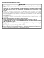
[INSTALLATION PRECAUTIONS]
CAUTION
! Use the PLC in an environment that meets the general specifications contained in
CPU module user's manual.
Using this PLC in an environment outside the range of the general specifications
may cause electric shock, fire, malfunction, and damage to or deterioration of the
product.
! Insert the module's mounting latch into the base unit's mounting cutout while
pressing the module's loading lever, which is located at the bottom of the module.
Improper installation may result in a malfunction or breakdown, or may cause the
module to fall off.
To install the module in a place subject to strong vibration or impact, secure it with
mounting.
! Tighten the screw within the range of specified torque.
Loose screws may result in malfunctioning or cause the module to fall off.
If the screws are too tight, it may damage the screws, and as a result the module
may malfunction or fall off.
! Switch all phases of the external power supply off when mounting or removing the
module.
Not doing so may cause damage of the product.
! Do not directly touch the conductive area or electronic components of the module.
Doing so may cause malfunction or failure in the module.
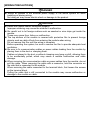
[WIRING PRECAUTIONS]
DANGER
! Switch all phases of the external power supply of the whole system off when
installing or placing wiring.
Not doing so may cause electric shock or damage to the product.
CAUTION
! Solder the coaxial cable's connector properly.
Improper soldering may cause the module to malfunction.
! Be careful not to let foreign matters such as sawdust or wire chips get inside the
module.
These may cause fires, failure or malfunction.
! The top surface of the module is covered with protective film to prevent foreign
objects such as cable offcuts from entering the module when wiring.
Do not remove this film until the wiring is complete.
Before operating the system, be sure to remove the film to provide adequate heat
ventilation.
! Be sure to fix communication cables or power cables leading from the module by
placing them in the duct or clamping them.
Cables not placed in the duct or without clamping may hang or shift, allowing them
to be accidentally pulled, which may cause a module malfunction and cable
damage.
! When removing the communication cable or power cables from the module, do not
pull the cable. When removing the cable with a connector, hold the connector on
the side that is connected to the module.
When removing the cable connected to the terminal block, first loosen the screws
on the terminal block.
Pulling the cable that is still connected to the module may cause malfunction or
damage to the module or cable.
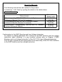
About the Manuals
The following manuals are also related to this product.
In necessary, order them by quoting the details in the tables below.
Related Manuals
Manual name
Q corresponding MELSECNET/H Network System
Reference Manual (PLC to PLC network)
Q corresponding MELSECNET/H Network System
Reference Manual (Remote I/O network)
Q/QnA/Q4AR corresponding MELSECNET/10 Network
System Reference Manual
Manual No.
(Model code)
SH-080049
(13JF92)
SH-080124
(13JF96)
IB-66690
(13JF78)
Conformation to the EMC Directive and Low Voltage Instruction
For details on making Mitsubishi PLC conform to the EMC directive and low voltage
instruction when installing it in your product, please refer to Chapter 3,"EMC
Directive and Low Voltage Instruction" of the PLC CPU User's Manual(Hardware).
The CE logo is printed on the rating plate on the main body of the PLC that conforms
to the EMC directive and low voltage instruction
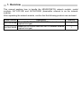
1. Overview
This manual explains how to handle the MELSECNET/H network module, model
numbers QJ71LP21GE and QJ72LP25GE (hereinafter referred to as the network
module).
After unpacking the network module, confirm that the following products are enclosed.
Model number
Description
Model QJ71LP21GE MELSECNET/H network module
QJ71LP21GE
(optical link type)
Model QJ72LP25GE MELSECNET/H network module
QJ72LP25GE
(optical link type)
Quantity
1
1
2. Performance Specifications
2.1 Performance specifications for the network module.
(1) QJ71LP21GE
Item
Maximum number of link points
per network
Specifications
LX/LY
LB
LW
PLC to PLC
Maximum
network
number of link
points per
Remote I/O
station
network
Communication speed
Communication method
Synchronous method
Transmission path format
Maximum number of networks
Maximum number of groups
PLC to PLC
Number of
network
connected
Remote I/O
stations
network
Overall distance
Distance between stations
Connection cable
Applicable connector
Number of I/O occupied points
5 VDC current consumption (A)
External dimensions (mm (in.))
Weight (kg )
MELSECNET/H mode *1
(PLC to PLC network/
Remote I/O network)
8192 points
19383 points
19383 points
MELSECNET/10 mode *1
(PLC to PLC network)
8192 points
8192 points
8192 points
{(LB + LY) /2 + LW × 2) ≤ 2000 bytes
Remote master station to Remote I/O station
Remote I/O station to Remote Master station
{(LB + LY) /2 + LW × 2) ≤ 1600 bytes
10Mbps
Token ring
Frame synchronous method
Duplex loop
239
32
64 stations (control station: 1, normal station: 63)
65 stations (Remote master station: 1, Remote I/O station: 64)
30 km (98430 ft.)
62.5GI optical cable: 2km (6562 ft.)
Optical fiber cable (Arranged by user *2)
2-core optical connector plug (Arranged by user *2)
32 points (I/O assignment: intelligent 32 points)
0.55
98 (3.86) (H) × 27.4 (1.08) (W) × 90 (3.54) (D)
0.11
(2) QJ72LP25GE
Item
Specifications
LX/LY
8192 points
LB
16383 points
LW
16383 points
Remote master station to Remote I/O station
Maximum number of link points
Remote I/O station to Remote Master station
per station
{(LB + LY) /2 + LW × 2) ≤ 1600 bytes
X + Y ≤ 4096 point
Maximum number of link points
When X/Y number overlaps, only one side becomes the object of
per station
the point.
Communication speed
10Mbps
Communication method
Token ring
Synchronous method
Frame synchronous method
Transmission path format
Duplex loop
Maximum number of networks
239
Maximum number of groups
32
65 stations
Number of connected stations
(Remote master station: 1, Remote I/O station: 64)
Overall distance
30 km (98430 ft.)
Distance between stations
62.5GI optical cable: 2km (6562 ft.)
Connection cable
Optical fiber cable (Arranged by user *2)
Applicable connector
2-core optical connector plug (Arranged by user *2)
Base unit installation position
CPU slot
5 VDC current consumption (A)
0.89
External dimensions (mm (in.))
98 (3.86) (H) × 27.4 (1.08) (W) × 90 (3.54) (D)
Weight (kg )
0.15
*1: Mode selection is performed using network parameters.
*2: Specialised training and specific tools are required to connect the connector to the optical-fiber
cable; the connector itself is a custom product. Please contact your nearest Mitsubishi Electric
Europe GmbH when purchasing these items.
For general specifications of the network module, refer to the user's manual for the CPU that is to be
used.
Maximum number of link points
per network
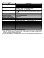
2.2 62.5GI type fiber-optic cable specifications
(1) Applicable cable specifications
" The specifications for the 62.5GI cable are given below.
" If you prepare a 62.5GI cable yourself, it must comply with the specifications
indicated below.
Item
Specification
Fiber type
GI (graded index) type multimode quartz glass
Core diameter
62.5µm
Clad diameter
125µm
Transmission loss
3dB/km or less
Wave length
0.85µm
Transmission band
300 MHz km or more
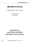
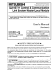
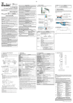
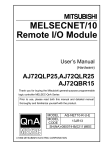
(2) Cable loss
Conversion cable (1m) *1
QJ71LP21GE
Adaptor
QJ72LP25GE
IN
SD
RD
OUT
SD
RD
Optical
module
5.5 dB or less
Conversion cable (1m)
Adaptor
SD IN
RD
Connection loss: 1 dB (max.)
Connection loss: 1 dB (max.)
Total cable loss = 7.5 dB or less
*1: Conversion cable
Conversion Type
Cable
AGE-1P-CA/FC1.5M-A
CA type ↔ FC type
AGE-1P-CA/ST1.5M-A
CA type ↔ ST type
AGE-1P-CA/SMA1.5M-A
CA type ↔ SMA type
Purchased from: Mitsubishi Electric Europe GmbH
SD
OUT
RD
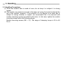
3. Handling
3.1 Handling Precautions
(1) Since the module case is made of resin, do not drop it or subject it to strong
impact.
(2) The module can easily be secured to the base unit using the hooks located at the
top of the module. However, if the module is to be placed in an area that is
subject to strong vibration or impact, we recommend that it be secured with
module mounting screws (provided by the user). In that case, tighten the module
mounting screws within the following range.
Module mounting screws (M3 × 12): The range of clamping torque is 36 to 48
N·cm .
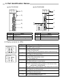
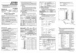
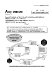
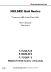
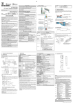
4. Part Identification Names
(a) QJ71LP21GE
(b) QJ72LP25GE
QJ71LP21GE
MNG
D.LINK
RD
L ERR.
REM.
D.LINK
RD
L ERR.
1)
90 1
4 56
23
78
90 1
78
01
EF 2
4)
BCD
MODE
789
4)
3)(Left side)
RESET
F01
89
67 A
345
6)
IN
6)
IN
BCD
MODE
2)
3)
4 56
23
X1
RUN
T.PASS.
SD
ERR.
1)
RS-232
STATION NO.
X10
QJ72LP25GE
345
RUN
T.PASS.
SD
ERR.
5)
STATION NO.
90 1
456
23
OUT
78
6)
OUT
X10
6)
90 1
4 56
23
78
X1
QJ72LP25GE
QJ71LP21GE
Number
1)
2)
3)
Name
Display LED
RS-232 connector
Station number setting switches
Number
4)
5)
6)
Name
Mode setting switch
RESET switch
Connector
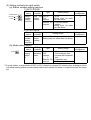
(1) Display contents for LEDs
LED name
RUN
QJ71LP21GE
RUN
T.PASS
SD
ERR.
MNG
D.LINK
T. PASS
RD
L ERR.
SD
QJ72LP25GE
RUN
T.PASS
SD
ERR.
ERR.
REM.
D.LINK
RD
MNG
L ERR.
REM.
D. LINK
RD
L. ERR.
Display contents
On: Operating normally
Off: WDT error occurred
On: Executing baton pass
Flicker: Executing test
Off: Baton pass not yet executed (host is disconnecting)
On: Data being transmitted
Off: Data not yet transmitting
On: Setting error occurred
Flicker: Error detected by a test
Off: No setting error
On: Operating as a control station or sub control station
Off: Operating as a normal station
On: Operating mormally
Flicker: Flash ROM is being written or the device of the
parameter is being tested.
Off: WDT error, Fuse break off, Unit verify error occurred.
On: Data link being executed
Off: Data link not yet executed
On: Data being received
Off: Data not yet received
On: Communication error occurred
Off: No communication error
(2) Setting contents for each switch
(a) Station number setting switches
1) QJ71LP21GE
STATION NO.
10s unit
X10
1s unit
X1
Switch
name
Station
number
setting
switches
Setting
Type
content
Sets the PLC to
station
PLC
number
network
Remote I/O
network
Setting range
1 to 64
Setting error for other
than the above
0: Remote master
station
Setting error for other
than the above
Setting at time
of shipment
1
2) QJ72LP25GE
Switch
name
Station
number
setting
switches
Setting
Setting at time
Setting range
content
of shipment
Sets the 1 to 64: Remote I/O station
1
station
Setting error for other than the above
number
(b) Mode setting switch
MODE
Switch
name
Mode
setting
switch
*1
Setting
Type
content
Sets the PLC to
operating PLC
mode
network
"
Remote I/O
network
Setting range
0: On-line
1: Self-loopback test
2: Internal self-loopback
test
3: Hardware test
5 to F: Use prohibited
Setting at time
of shipment
0
*1:Contorl station, normal station of PLC to PLC network or remote I/O network when making to online
with Mode setting switch remote master station and remote I/O station is made the switch the same
set.
5. External Wiring
5.1 Precautions for Laying Optical Fiber Cables
(1) When connecting an optical fiber cable, the following restrictions on the bending
radius must be observed. Please confirm bending radius of the cable with the
cable used.
(2) Please maintain the optical fiber cable permissible bending radius with a checking
tool.
Enquiries for the checking tool for optical fiber cable bending radius maintenance
are handled by Mitsubishi Electric Europe GmbH. Please contact Mitsubishi
Electric Europe GmbH for detail.
(3) When laying the optical-fiber cable, do not touch the fiber core of the cable
connector or module connector, or let dirt or dust collect on it.
If oil from the hands, dirt or dust should adhere to the core, the transmission loss
will increase, causing a malfunction in the data link.
(4) When attaching or detaching the optical-fiber cable to/from the module, hold the
cable connector securely with the hands.
(5) Connect the cable connector and module connector securely until you hear a
"click" sound.
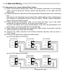
(6) Connect the optical fiber cables as shown below.
(a) QJ71LP21GE-QJ71LP21GE
QJ71LP21GE
QJ71LP21GE
QJ71LP21GE
IN
SD
RD
IN
SD
RD
IN
SD
RD
OUT
SD
RD
OUT
SD
RD
OUT
SD
RD
(b) QJ71LP21GE-QJ72LP25GE
QJ71LP21GE
QJ72LP25GE
QJ72LP25GE
IN
SD
RD
IN
RD
SD
IN
RD
SD
OUT
SD
RD
OUT
RD
SD
OUT
RD
SD
Optical module
Optical fiber cable
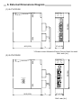
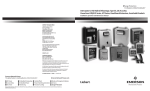
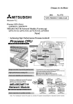
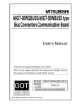
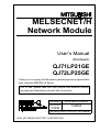
6. External Dimensions Diagram
(1) QJ71LP21GE
QJ71LP21GE
MNG
D.LINK
RD
L ERR.
23
456
X10
90 1
STATION NO.
78
RUN
T.PASS.
SD
ERR.
90 1
456
23
98(3.86)
78
X1
IN
89 A
01
EF 2
67
3 45
BCD
MODE
OUT
QJ71LP21GE
90.5(3.56)
*1
27.4(1.08)
*1:Please contact Mitsubishi Electric Europe GmbH for detail.
Unit: mm (in.)
(2) QJ72LP25GE
QJ72LP25GE
RUN
T.PASS.
SD
ERR.
REM.
D.LINK
RD
L ERR.
98(3.86)
RS-232
IN
RESET
0
8
C
MODE
STATION NO.
4
90 1
45 6
23
78
X10
90 1
45 6
23
78
X1
OUT
QJ72LP25GE
90.5(3.56)
*1
27.4(1.08)
Unit: mm (in.)
Warranty
Mitsubishi will not be held liable for damage caused by factors found not to be the cause of
Mitsubishi; machine damage or lost profits caused by faults in the Mitsubishi products;
damage, secondary damage, accident compensation caused by special factors unpredictable
by Mitsubishi; damages to products other than Mitsubishi products; and to other duties.
For safe use
" This product has been manufactured as a general-purpose part for general industries, and
has not been designed or manufactured to be incorporated in a device or system used in
purposes related to human life.
" Before using the product for special purposes such as nuclear power, electric power,
aerospace, medicine or passenger movement vehicles, consult with Mitsubishi.
" This product has been manufactured under strict quality control. However, when installing
the product where major accidents or losses could occur if the product fails, install
appropriate backup or failsafe functions in the system.
Country/Region Sales office/Tel
U.S.A
Mitsubishi Electric Automation Inc.
500 Corporate Woods Parkway Vernon
Hills, IL 60061
Tel : 1-847-478-2100
Brazil
MELCO-TEC Rep. Com.e Assessoria
Tecnica Ltda.
Av. Rio Branco, 123-15 ,and S/1507,
Rio de Janeiro, RJ CEP 20040-005,
Brazil
Tel : 55-21-221-8343
Germany
Mitsubishi Electric Europe B.V. German
Branch
Gothaer Strasse 8 D-40880 Ratingen,
GERMANY
Tel : 49-2102-486-0
U.K
Mitsubishi Electric Europe B.V. UK
Branch
Travellers Lane, Hatfield, Herts., AL10
8XB,UK
Tel : 44-1707-276100
Italy
Mitsubishi Electric Europe B.V. Italian
Branch
Centro Dir. Colleoni, Pal. Perseo - Ingr.2
Via Paracelso 12, 20041 Agrate B.,
Milano, Italy
Tel:39-039-6053301
Spain
Mitsubishi Electric Europe B.V. Spanish
Branch
Pol. Ind. "Can Magi"- C/.Joan Buscalla,
2-4-A.C.420
08190 Sant Cugat del Valles, Barcelona,
Spain
Tel:34-935-653135
South Africa
MSA Manufacturing (Pty) Ltd.
P O Box 39733 Bramley 201 8
Johannesburg, South Africa
Tel : 27-11-444-8080
Hong Kong
Ryoden International Ltd.
10th Floor, Manulife Tower, 169 Electric
Road, North Point, HongKong
Tel : 852-2887-8870
Country/Region Sales office/Tel
China
Ryoden International Shanghai Ltd.
3F Block5 Building Automation
Instrumentation Plaza 103 Cao Bao Rd.
Shanghai 200233 China
Tel : 86-21-6475-3228
Taiwan
Setsuyo Enterprise Co., Ltd.
6F., No.105 Wu-Kung 3rd.RD, Wu-Ku
Hsiang, Taipei Hsine, Taiwan R.O.C.
Tel : 886-2-2299-2499
Korea
HAN NEUNG TECHNO CO.,LTD.
1F Dong Seo Game Channel Bldg.,
660-11, Deungchon-dong Kangsec-ku,
Seoul, Korea
Tel : 82-2-3668-6567
Singapore
Mitsubishi Electric Asia Pte, Ltd.
307 ALEXANDRA ROAD #05-01/02,
MITSUBISHI ELECTRIC BUILDING
SINGAPORE 159943
Tel : 65-473-2480
Thailand
F. A. Tech Co.,Ltd.
898/28,29,30 S.V.City Building,Office
Tower 2,Floor 17-18 Rama 3 Road,
Bangkpongpang, Yannawa,
Bangkok 10120
Tel : 66-2-682-6522
Indonesia
P.T. Autoteknindo SUMBER MAKMUR
Jl. Muara Karang Selatan Block A Utara
No.1 Kav. No.11 Kawasan Industri/
Pergudangan Jakarta - Utara 14440
Tel : 62-21-663-0833
India
Messung Systems Put,Ltd.
Electronic Sadan NO:111 Unit No15,
M.I.D.C BHOSARI,PUNE-411026
Tel : 91-20-7128927
Australia
Mitsubishi Electric Australia Pty. Ltd.
348 Victoria Road, PostalBag, No 2,
Rydalmere, N.S.W 2116, Australia
Tel : 61-2-9684-7777
HEAD OFFICE:MITSUBISHI DENKI BLDG MARUNOUCHI TOKYO 100-8310 TELEX:J24532 CABLE MELCO TOKYO
NAGOYA WORKS:1-14, YADA-MINAMI 5, HIGASHI-KU, NAGOYA, JAPAN
When exported from Japan, this manual does not require application to the Ministry
of International Trade and Industry for service transaction permission.
Specifications subject to change without notice.
Printed in Japan on recycled paper.