1
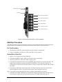
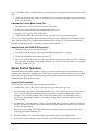
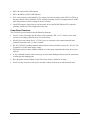
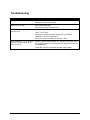
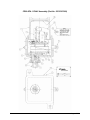
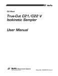
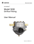
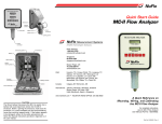
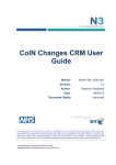
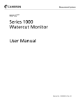
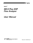
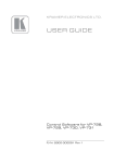
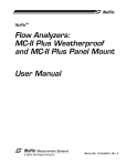
Clif Mock
CD20-SFA (115VAC)
Sampler Drive
User Manual
Manual No. 20165017, Rev. A
© 2004 NuFlo Technologies, Inc. All information contained in this publication is confidential and
proprietary property of NuFlo Technologies, Inc. Any reproduction or use of these instructions,
drawings, or photographs without the express written permission of an officer of NuFlo
Technologies, Inc. is forbidden.
All Rights Reserved.
Printed in the United States of America.
Manual No. 20165017, Rev. A
August 2004
Table of Contents
Description .................................................................................................................... 1
Installation and Wiring.................................................................................................. 1
Start-Up Procedure ....................................................................................................... 2
Pre-Test Procedure ..................................................................................................... 2
Repeat Mode Check-Out ............................................................................................. 2
External Input Pulse Mode Check-Out ........................................................................ 3
Sample Probe and CD20-SFA Check-Out................................................................... 3
Motor Control Operation............................................................................................... 3
Control Card Functions................................................................................................ 3
Power Board Functions ............................................................................................... 4
Troubleshooting ............................................................................................................ 5
Sampler Drive Schematic ............................................................................................. 6
Bill of Materials.............................................................................................................. 7
August 2004
i
ii
August 2004
Description
The CD20-SFA 115VAC Control and Drive Assembly (Part No. 50132307668) is engineered specifically
for use with the True-Cut C-Series sample probes. It comprises the following components:
•
a motor speed control that provides pulse input (flow-proportional) control of the sample probe.
When a “start” pulse is received at the CD20-SFA control card input, the probe is rotated 180 degrees
to capture and discharge a single 1.5-ml isokinetic sample. On a horizontal line, the probe is stopped
in the closed position, while on a vertical line, the probe is stopped in the open position. A probe
failure alarm relay provides an output contact that is open as long as a sample has been taken within
the alarm delay period set on the control card potentiometer. Alarm delays ranging from 6 seconds to
6 minutes can be set.
•
a 9VDC gear motor with a gear ratio of 150:1
•
a cam with two high points located opposite each other mounted on the gear motor output shaft.
•
a proximity switch mounted in the hub assembly opposite the cam. When a high point on the cam is
opposite the proximity switch, the PROX (“Hold”) LED will be illuminated. This signal indicates the
sample probe is at the stop and “hold” position.
•
a coupling, jam nut, and hub, which allow the CD20-SFA Control and Drive Assembly to be mounted
directly to the C-Series sample probe. No brackets or supports are required, but they are advisable on
pipelines with some vibrations.
•
an explosion-proof housing encloses the complete assembly. Two ¾-in. NPT holes allow connection
of the 115VAC line power and input pulse (for flow proportional sampling). A ½-in. breather plug is
installed on one side of the enclosure, and a ½-in. conduit plug is installed on the opposite side of the
enclosure.
Installation and Wiring
The CD20-SFA mounts directly to the C-Series sample probe via the DC-2 coupling. The DC-2 coupling
should be hand-tightened only to ensure that the internal retaining ring is not pushed out of its groove. If
the DC-2 coupling is over-tightened at the CD20-SFA hub, the motor shaft will not engage the DC-1 (not
shown) coupling on the probe.
Use the following steps to install field wiring to the CD20-SFA-115VAC (Figure 1):
1. Connect 115VAC power to 1TB-1 and 1TB-2.
2. Connect the flow pulse input contact to 1TB-5 (signal) and 1TB-6 (common). If an open collector
transistor driver is used, the collector must connect to 1TB-5 and the emitter must connect to 1TB-6.
Note—The pulse contact must be closed for at least 5 msec to produce a start pulse.
Note—If an electronic square wave is used, it must have a pulse amplitude of 12VDC. A 5VDC square
wave will not work.
Connect the sample failure alarm relay contact to 1TB-3 and 1TB-4. The contact will remain open as long
as sampling occurs within the alarm delay period. This contact is rated for 90VA resistive and 30VA
inductive loads. It is suitable for use with 115VAC low current.
August 2004
1
PROX (“Hold”) LED
I-Limit LED
1TB-6 Pulse Input (Emitter)
1TB-5 Pulse Input (Collector)
1TB-4 (Failure Alarm)
1TB-3 (Failure Alarm)
1TB-2 115-VAC Power (N)
1TB-1 115-VAC Power (H)
Figure 1—Field wiring of CD20-SFA (115VAC) assembly
Start-Up Procedure
The start-up procedure consists of four steps: a pretest, a repeat-mode checkout, an external input pulse
mode checkout, and a sample probe/control drive checkout. Each of these is described below.
Pre-Test Procedure
1. Disconnect the CD20-SFA control and drive assembly from the sample probe.
2. Connect a pushbutton switch across 1TB-5 and 1TB-6 for test purposes.
Repeat Mode Check-Out
1. Apply 115VAC input power to the CD20-SFA.
2. Verify that the PROX (“Hold”) LED is on when the motor is not turning.
3. Close the switch across 1TB-5 and 1TB-6 to apply a pulse.
4. Verify that the output shaft turns in a CLOCKWISE (CW) direction as you look at the shaft. The
sample probe will then be rotated COUNTERCLOCKWISE (CCW) when the CD20-SFA is
connected to it. If the direction of motor rotation is wrong, swap the motor armature leads at 2TB-1
and 2TB-2.
5. Verify that the CD20-SFA output shaft rotates 180 degrees and stops after each switch closure
input. It should take about 2.5 seconds for the motor to rotate 180 degrees and stop.
Note—Any switch closure made while the motor is turning is disregarded by the control.
6. Verify that the I-LIMIT LED blinks on momentarily during acceleration of the CD20-SFA motor.
After the motor reaches the 16-18 rpm running speed, the I-LIMIT LED should turn off.
2
August 2004
Note—The PROX (“Hold”) LED should be off while the motor is running and turned on when the motor
stops.
7. Verify that the alarm relay contact is closed after power is applied, and that it opens after the alarm
delay period has lapsed.
External Input Pulse Mode Check-Out
1. Disconnect the 115VAC input power from the CD20-SFA.
2. Remove the switch and wire in the external input pulse source.
3. Reapply 115VAC power to the CD20-SFA.
4. Verify that the CD20-SFA output shaft rotates 180 degrees for each external input pulse.
Note—Any internal coincidence pulses that provide the next “start” command for the CD20-SFA must
occur when the CD20-SFA is stopped and the PROX (“Hold”) LED is on. The maximum valid flow
proportional sampling rate is 2.5 seconds per sample (24 samples/min).
Sample Probe and CD20-SFA Check-Out
1. Disconnect VAC power from the CD20-SFA.
2. Mount the CD20-SFA to the sample probe and hand-tighten the DC-2 coupling.
3. Verify that the product line is full and pressurized.
4. Hold a 100-ml graduated beaker (or other applicable measuring device) under the probe’s discharge
port and collect 10 samples. Each sample should be 1.5-ml in size; the total volume for 10 samples,
therefore, should be 15 ml.
Motor Control Operation
The CD20-SFA motor control assembly consists of a control card and power board mounted to a ring
which in turn is mounted to the back of the CD20-SFA gear motor. All field connections are to terminal
block 1TB on the control card. The motor and proximity switch connections are made at the factory to
terminal block 2TB on the power board.
Control Card Functions
The CD20-SFA control card performs the following functions:
•
Components C7, R12, CR5, and a U4 gate provide a 100-msec power-up reset.
•
An alarm delay timer circuit is implemented with U3, C6, C10, R4, R1 and a U4 gate. This circuit is
reset every time a sample is taken and on initial power-up. U3 counts oscillator pulses and deenergizes relay 1CR after counting 2048 clock pulses from U4 pin 6. The alarm delay time is
increased by adjusting R1 clockwise. Alarm delays ranging from 6 seconds to 6 minutes can be
selected via R1.
•
An input filter circuit connected to 1TB-5 buffers incoming pulses from an external flow measuring
device. The filter has a 2msec time constant, and the input pulse duration must be at least 5 msec to
assure a start pulse output.
•
When set by a start pulse, the RUN/STOP latch U5A outputs the speed command voltage to the
summing point control amplifier U2A.
•
Amplifier U2B provides current feedback to the summing point control amplifier U2A.
•
Resistor R19 provides armature voltage feedback to the summing point control amplifier U2A.
August 2004
3
•
DS2 is the current limit LED indicator.
•
DS1 is the PROX (“Hold”) LED indicator.
•
U2C is the proximity switch amplifier. The voltage across the proximity switch (2TB-3 to 2TB-4 on
the power board) will be nominally +8VDC when the proximity switch is sensing metal and +4VDC
when the proximity switch is sensing an absence of metal.
•
Latch U5B outputs a single 20-msec one-shot pulse to reset the RUN/STOP latch U5A when the
proximity switch first senses a high point on the cam.
Power Board Functions
The CD20-SFA power board provides the following functions:
•
Fuse F1 (2-amp, fast-acting) provides short circuit protection. ZD1, a 33V "crowbar" zener diode,
provides over voltage protection for the rest of the circuit.
•
Diode D2 prevents current flow if +115VAC power is connected to the common terminal and a
ground is connected to the +115VAC terminal.
•
Q4, an LT1074CT switching regulator and associated circuitry efficiently convert the +115VAC into
a regulated +6.3VDC motor supply voltage.
•
The control card uses motor armature feedback to set the speed command to the motor driver power
FET Q2.
•
A stop command from the control card to Q1 provides motor braking which prevents the motor from
coasting past the stopping point.
•
R6 is the motor current feedback resistor. The motor current is limited to 3.0 amps.
•
Fuse F2 (2-amp, slow blow) will open in less than 1 minute if the motor is stalled (locked rotor).
4
August 2004
Troubleshooting
Problem
Probable Cause
Input power fuse F1 is open.
Input power surge above 33VDC.
Short circuit on the power board.
Motor fuse F2 is open.
Motor stall (locked rotor).
Short circuit in motor armature circuit.
Motor does not run and the current
limit LED is off.
Input power not on or connected backwards.
Fuse F1 or F2 open.
Open circuit to motor armature. Check 2TB-1 and 2TB-2.
CD20-SFA-115VAC control failure.
No pulses of proper amplitude at 1TB-5 to 1TB-6.
Motor continues to run. The PROX
(“Hold”) LED never comes on or
blinks on and off.
Broken or open proximity switch wire. Check at 2TB-3 and 2TB-4.
The proximity switch is not sensing the high points of the cam due
to misalignment.
CD20-SFA-115VAC control failure (power supply board).
August 2004
5
CD20-SFA 115VAC Assembly (Part No. 50132307668)
6
August 2004
CD20-SFA-115VAC Assembly (Part No. 50132307668) Parts List
ITEM
1
2
3
4
5
6
7
8
QTY
1
1
1
1
1
1
1
1
CONTROL NO.
50142304856
50142307664
50142307700
50142382006
50142200170
50142150932
50142307695
50142381667
9
10
11
12
13
14
15
1
1
1
1
1
4
11
50142309906
50142307686
50142304632
50142307696
50142200101
50025400765
50142307693
16
17
18
19
11
1
1
1
50142307694
50142304642
50142400194
50142200109
20
1
50142304858
August 2004
DESCRIPTION
ENCLOSURE
SPEED CONTROL, 115VAC
MOTOR, CS/CD DRIVE
HUB ASSEMBLY, CD DRIVE
JAM NUT, CS/CD DRIVE
DRIVE COUPLING ASSY, DC-2
DRIVE SHAFT
COUPLING, CAM/MOTOR
ASSEMBLY
PROXIMITY SWITCH, EI-08-01-NACS
ADAPTER PLATE
PLUG, 1/2", CONDUIT
SNAP RING
TAG, ELECTRICAL, CD/DS DRIVE
DRIVE SCREW, 2 x 3/16"
BINDER HD SCREW, #8-32NC x 1/2"
LG
WASHER HUB SCREW, #8
BREATHER, 1/2" PLUG
JUMPER, RDI #J4-02
CAUTION TAG, CD20-SFA, CD20SFA, CD30 DRIVES
HUMISORB PACKET, #107HX 4 x 4
7
WARRANTY - LIMITATION OF LIABILITY: Seller warrants only title to the products,
software, supplies and materials and that, except as to software, the same are free from
defects in workmanship and materials for a period of one (1) year from the date of
delivery. Seller does not warranty that software is free from error or that software will run
in an uninterrupted fashion. Seller provides all software "as is". THERE ARE NO
WARRANTIES, EXPRESS OR IMPLIED, OF MERCHANTABILITY, FITNESS OR
OTHERWISE WHICH EXTEND BEYOND THOSE STATED IN THE IMMEDIATELY
PRECEDING SENTENCE. Seller's liability and Buyer's exclusive remedy in any case of
action (whether in contract, tort, breach of warranty or otherwise) arising out of the sale or
use of any products, software, supplies, or materials is expressly limited to the
replacement of such products, software, supplies, or materials on their return to Seller or,
at Seller's option, to the allowance to the customer of credit for the cost of such items. In
no event shall Seller be liable for special, incidental, indirect, punitive or consequential
damages. Seller does not warrant in any way products, software, supplies and materials
not manufactured by Seller, and such will be sold only with the warranties that are given
by the manufacturer thereof. Seller will pass only through to its purchaser of such items
the warranty granted to it by the manufacturer.
NuFlo Measurement Systems
14450 John F. Kennedy Blvd.
Houston, TX 77032
www.nuflotech.com
North America:
800-654-3760
281-582-9500 (Houston)
877-891-6540 (Calgary)
UK:
44-1243-826741
Singapore:
65-6737-0444