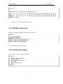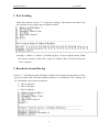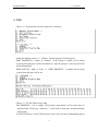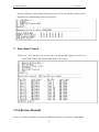
1
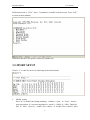
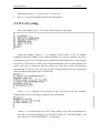
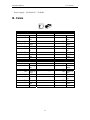
ISCOM 1024M(A)
User Manual
Raisecom Technology
200503
RAISECOM TECHNOLOGY
Content
.................................................................................1
1、ISCOM 1024M(A) ......................................................................................................3
1.1Package ................................................................................................................3
2、 Deploying ..................................................................................................................3
2.1 ISCOM 1024M(A) on desktop............................................................................3
2.2 ISCOM 1024M(A) on cabinet.............................................................................3
3、 Configuring and managing ISCOM 1024M(A) ........................................................4
3.1 introduction of manual ........................................................................................4
3.2 How to manage ISCOM 1024M(A) ....................................................................4
3.2.1 Log in .......................................................................................................4
3.2.2PORT SETUP............................................................................................5
3.2.3VLAN setting ............................................................................................6
3.2.4 Modify password......................................................................................7
3.2.5 advanced setting .......................................................................................7
3.2.6 Restore Default.......................................................................................10
3.2.7 Reset Syetem .......................................................................................... 11
3.2.8 Exit ......................................................................................................... 11
4. LED Description ......................................................................................................... 11
5. Troubleshooting........................................................................................................... 11
5.1 How to resolve link LED off ............................................................................. 11
6.2 Q & A ................................................................................................................12
7. Specifications ..............................................................................................................12
A. Features and specifications.................................................................................12
B. Cable...................................................................................................................13
RAISECOM TECHNOLOGY
1、ISCOM 1024M(A)
ISCOM 1024M(A) is an Ethernet switch with VLAN and QoS. It can provide
24X10/100Mbps RJ45 interfaces and support Local craft terminal management through
Console. For simplifying the configuration, it can be configured as NO VLAN and
Concentration VLAN mode. If it is configured as Concentration VLAN mode, every
port is independent VLAN and supports flow control and rate-limit controlfor uploading.
ISCOM 1024M(A) is your best choice for connection of SME.
1.1Package
z
z
z
z
1 unit ISCOM 1024M(A)
1 AC power supply cable
1 RS232 connectivity cable
2 screw for bracket used on cabinet
2、 Deploying
2.1 ISCOM 1024M(A) on desktop
1.
2.
ISCOM 1024M(A) is put on desktop
ISCOM 1024M(A) is connected to network
2.2 ISCOM 1024M(A) on cabinet
ISCOM 1024M(A) can be installed on the EIA 19” cabinet using the screws and
brackets in the package.
ISCOM1024M(A)
User manual
3、 Configuring and managing ISCOM
1024M(A)
3.1 introduction of manual
[1]Introduction
ISCOM 1024M(A) provides friendly GUI and manual interface which include the
functions as following:
z Configure the parameters of system and ports
z Configure VLAN
z Configure packet filtering
z Configure bandwidth for upload
[2]Method for management
z
ISCOM 1024M(A) is managed by CONSOLE.
Local Craft Terminal management
ISCOM 1024M(A) default setting for console [bits per second:9600,data bits:8,
parity:0,stop bits:1,flow control:None],VT100 type terminal.
Log in ISCOM 1024M(A)
When ISCOM 1024M(A) is logged in at first time,the system will ask password
which is 1234 as default. It can be modified when logged in.
3.2 How to manage ISCOM 1024M(A)
ISCOM 1024M(A) provides an interface driven by manual.
3.2.1 Log in
The prompt as following on the screen:
4
ISCOM1024M(A)
User manual
Default password is “1234”. Note:Command is available with lowercase. Press “ESC”
to return to main manual.
Under this interface, the option is chosen by number key.
3.2.2PORT SETUP
Choose “1” to enter the screen as following in the main manual.
1.
Modify setting
Press “m” to modify the setting including:Admin(e:open,d:close)、Auto(e:
auto negotiation,d:non auto negotiation)、speed (1:100M,0:10M)、Duplex(f:
full,h:half)、flow-C(e:enable flow control,d:disable flow control). After
5
ISCOM1024M(A)
2.
User manual
modification, press “y” to save, press “n” not to save.
press “q” to quit this manual and return to main manual.
3.2.3VLAN setting
Under this manual, press “2” to enter VLAN manual as following:
Under this manual, choose “1” to configure VLAN mode to suit to multiple
residential customer building. (Note: under this mode, every port to customer can not be
communicated. However, all of them can communicate with uplink port to access upper
level device. This mode is usually used on the broadband access for multi-tenant ) the
system will ask to assign the specific uplink port, then the system will generate
automatically VLAN for every port to access the customer and these VLAN on the ports
can be included in the uplink port. As following:
Choose “2” to configure VLAN based on port. the system will ask manually
configuration for VLAN on port according to the requirement.
Choose “3” to configure tag for VLAN. Tag(u:untag,t:tag) is the configuration for
the status of port and belonging of VLAN ID PVID(0-23). “TAGGED PORT” can
not connect to “UNTAGGED PORT”, as following:
6
ISCOM1024M(A)
User manual
Choose “4” to remove all of VLAN tag.
3.2.4 Modify password
Choose “3-Password Setup” to modify the password.
User can configure new password.
3.2.5 advanced setting
Choose “4” to access “ Advanced Setup”.
7
ISCOM1024M(A)
User manual
1. Port Locking
Under this manual, choose “1” to enter port locking. This function can allow only
one customer to use specific port of Ethernet switch.
Locking(e:enable, d:disable). “Switching Aging” is open at default setting. When
the current customer’s MAC ID is aged out, another MAC ID will become this
“sole” customer.
2. Broadcast storm filtering
Choose “2”, if broadcast storm filtering is enable, these broadcast storm packet will be
given up within 50ms when the broadcast packet is over threshold. The customer can
set 3 thresholds values based on all ports.
1:10% for all ports;
2:20% for all ports;
3:40% for all ports;
8
ISCOM1024M(A)
User manual
3. COS
Choose “3”, this function can set 4 queues for customers.
Under this manual, choose “1”. Global:Switch supports COS based port.
PORT PRIORITY(e:enable, d:disable):if the setting is enable, all of packet
receiving from this port will be forwarded as a specific priority. VLAN tag and TOS
will be disregarded.
PORT QUEUE(1:high,0:low):if “PORT PRIORITY” is enable, the receiving
packet from this port will be set.
Choose “2”, VLAN/TOS Priority Map
TOS PRIORITY:if it is enable, TOS priority information will be deal more in
advanced than VLAN tag;otherwise,VLAN will be deal more in advanced than
TOS priority.
VLAN/TOS Priority:VLAN/TOS Priority value can be set into 2 transmitting queues.
9
ISCOM1024M(A)
User manual
Totally, 8 different VLAN and TOS Priority value can be set and these values can be
dispatched to 2 transmitting queues of each port.
3. Rate-limit Control
Choose “4”, this function can set the rate for upload and support 9 level rate
(64K,128K,256K,512K,1M,4M,10M,20M,和 No Limit)
3.2.6 Restore Default
Choose “5. Restore Default” to restore the Ethernet switch to exit factory configuration.
10
ISCOM1024M(A)
User manual
3.2.7 Reset Syetem
Choose “7. Reset System” to reset Ethernet switch.
3.2.8 Exit
Choose “8. Exit” to exit interface of configuration to return log interface.
4. LED Description
LED
PWR
SYS
LNK / ACT
status
On
blinkin
g
On
description
Power on
Switch can be configured
Blinkin
g
Green
Packet is transmitted or received
Speed is 100Mbps
Yellow
Speed is 10Mbps
Link status is OK
5. Troubleshooting
5.1 How to resolve link LED off
The possible reasons are following:
z the power supply is off
z the type of cable is not right one
z physical interface of switch has some problem
11
ISCOM1024M(A)
User manual
6.2 Q & A
1. Computer A can access computer B through Ethernet switch. However, computer A
can not access computer C.
9 Computer A and computer C are maybe not in the same VLAN. Please check the
VLAN configuration through console port.
9 The network has some problem including Computer C. please check LED
LNK/ACT of computer C and try to connect other device using this interface.
9 Please check the NIC configuration of computer C.
7. Specifications
A. Features and specifications
z
z
z
z
z
z
z
24 x 10/100Mbps RJ45 interfaces
Support MDI or MDI-X
Support CONSOLE
Support flow control
Support rate-limit for uploading
Support VLAN
Support QoS
Complied standard:IEEE802.3 10Base-T,IEEE 802.3u 100Base-TX
Support VLAN based on ports up to 24
Dimension: 440Wmm x 120Dmm x 43.6Hmm
Store and forward: wire-speed
Mac table:4K
Buffer for packet:128K
Environment temp:0-50 centigrade degree
Humidity:
5% ~ 95%
Power consumption: く 15W
12
ISCOM1024M(A)
User manual
Power supply:160-240VAC,50-60Hz
B. Cable
Standard straight line
HUB / Switch
Pin#
#
1
RX+ white-gr
een
2
RX- green
3
TX+ white-or
ange
4
N/A blue
5
N/A white-bl
ue
6
TX- orange
7
N/A white-br
own
8
N/A brown
Standard cross over line
Hub /switch
Pin #
#
1
RX+ white-gr
een
2
RX- Green
3
TX+ white-or
ange
4
N/A blue
5
N/A white-bl
ue
6
TX- orange
7
N/A white-br
own
8
N/A brow
-----------------
NIC
Pin #
1
---------------------------------
2
3
---------------------------------
4
5
---------------------------------
6
7
-----------------
8
----
----
NIC
Pin#
1
-------
-------
2
3
4
5
----
----
6
7
8
13
#
RX+ white-gr
een
RX- green
TX+ white-or
ange
N/A blue
N/A white-bl
ue
TX- orange
N/A white-br
own
N/A brown
#
RX+ white-or
ange
RX- orange
TX+ white-gr
een
N/A blue
N/A white-bl
ue
TX- Green
N/A white-br
own
N/A brown