1
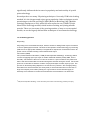
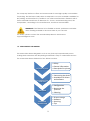
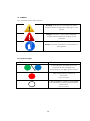
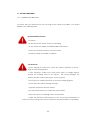
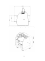
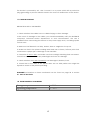
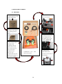
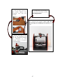
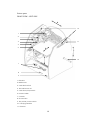
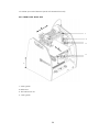
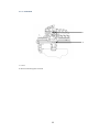
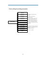
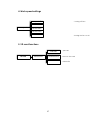
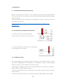
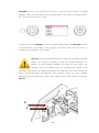
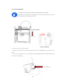
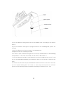
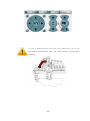
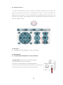
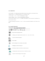
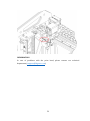
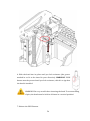
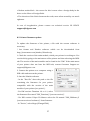
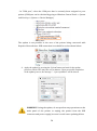
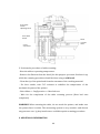
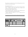
1
Spatial Printer
Advanced and reliable 3D printing platform with a patented head change system.
PURPOSE :
RAPID PROTOTYPING
SMALL SCALE PRODUCTION
SUPPORT OF MANUFACTURING PROCESSES
TABLE OF CONTENTS 2
Spatial Printer
Advanced and reliable 3D printing platform with a patented head change system.
PURPOSE :
RAPID PROTOTYPING
SMALL SCALE PRODUCTION
SUPPORT OF MANUFACTURING PROCESSES
TABLE OF CONTENTS 2
1. INTRODUCTION 5
1.1.
1.2.
1.3.
1.4.
1.5.
1.6.
1.6.1.
INTRODUCTORY COMMENTS
A FEW WORDS ON THE HISTORY OF 3D PRINTING
DESCRIPTION OF THE PROCESS OF 3D PRINTING
MATERIALS TO PRINT 9
STRUCTURE OF THE MANUAL 10
SYMBOLS 11
LIST OF SYMBOLS OCCURRING IN THE MANUAL 11
1.6.2. INDICATOR LIGHTS 11
2
1.7.
SAFETY MEASURES 12
1.7.1. GENERAL INFORMATION 12
1.7.2. WHEN MOVING THE PRINTER 14
1.7.3. ABOUT THE LOCATION OF PRINTER INSTALLATION
1.7.4. PRIOR TO STARTING 16
1.8. ENVIRONMENTAL PARAMETERS 16
2.
DESCRIPTION OF PRINTER 17
2.1. INITIAL STEPS 17
CONTENTS OF EQUIPMENT 19
2.2. CONSTRUCTION OF PRINTER 20
2.2.1. VIEW FROM FRONT - LEFT SIDE 20
2.2.2. VIEW FROM FRONT - RIGHT SIDE 21
2.2.3. REAR VIEW 22
2.2.4. EXTRUDER 23
2.3.
CONTROL BUTTONS 24
2.3.1. MAIN PANEL 24
2.3.2. PAUSE BUTTON 25
2.3.3. DESCRIPTION OF DISPLAY 25
2.3.4. MENU 26
3. PREPARATION 30
3.1. INSTALLATION OF SOFTWARE AND DRIVER 30
3.2. CONNECTION AND ENABLING OF PRINTER 31
3.3. CALIBRATION OF TABLE 31
3.4. MOUNTING FILAMENT 34
3.5. REMOVING FILAMENT 36
4. THE FIRST PRINT 37
4.1. CONNECTING THE PRINTER TO A COMPUTER 37
4.2. CONFIGURATION OF REPETIER-HOST SOFTWARE 37
3
4.3. FIRST PRINT 39
5. POST-PRINTING OPERATIONS 44
5.1. REMOVING THE PRINT 44
5.2. CLEANING 45
5.2.1. CLEANING THE PRINT HEAD 45
5.2.2. CLEANING OF OPERATING TABLE 45
5.3. TURNING OFF 46
6. STORAGE 46
7. SOFTWARE 47
7.1. GENERAL INFORMATION 47
7.2. LOCATION OF FACILITY 47
7.2.1. 3D VIEW 47
7.2.2. SHORTCUTS 48
7.2.3. LOCATION OF FACILITY 48
7.3. MANUAL CONTROLS 49
8. SERVICING 52
8.1. Replacement of filament
8.2. Replacement of Print Head 53
8.3. Maintenance of guides and ball screws 56
8.4. Maintenance of toothed belts /gear belts 56
8.5. Updating the Printer Firmware 57
9. Additional information 61
9.1. GUARANTEE 61
9.2. Tips / Common problems 63
9.3 How to design models
10. Printer specifications 64
11. Useful contacts 65
4
1. Introduction
1.1 Introduction
Thank you for choosing 3DGence One 3D printer. The following manual will introduce
you to the world of 3D printing, and enable you to smoothly negotiate your way
around it.
Before attempting to use the 3DGence One printer, we strongly urge you to read the
information contained in the manual and comply with it fully. This compliance will
help to prevent any future device failures.
In the event of problems or concerns please contact our technical department at
the following address: [email protected]
5
1.2. A FEW WORDS ON THE HISTORY OF 3D PRINTING
The date that is associated with the birth of spatial printing is the same year as
Orwell’s famous novel 1984, when Charles Hull (b. 1939, USA) invented a
method of stereolithography (SLA). However, the appearance of the first "print"
could be seen much earlier in history, as far back as ancient times when people
started welding. Yes, you have read it right, it's about the technique of welding
and soldering. Perhaps it is true that ancient people used primitive versions of
these techniques, and only in the nineteenth and twentieth century did these
methods become developed and modernized. The creation of welding torches
contributed to the spread of welding, and thereby new inventive methods of
joining metals. This, in turn, led to the invention of flame-plating, a technique
similar to the method of 3D printing, based on applying successive layers of
material – so-called incremental technology.
Reverting back to the topic of Charles Hull, it should be noted that not only did
he invent the SLA method connected to toughening the epoxy or acrylic resin
with the use of an ultraviolet light beam generated by a laser. He also made his
mark in the history of spatial printing in another very important way. He
developed a file with the extension stl, which is characteristic of 3D printing.
After that the development of 3D printing was very dynamic - Charles Hull
patented the SLA printing technique, founded the 3D system company (which is
still successful), and launched the first commercial 3D printer for sale (1992).
The market slowly began to get saturated, with companies competing to find
better methods of printing. 3D printing started to be applied in many important
areas, e.g. medicine - in 1999 the first attempts at transplantation commenced.
An important moment for the advancement of 3D printing was the year 2005,
when the first RepRap printer model was developed by Adrian Bowyer (born
1952, UK). RepRap printer is a device that can replicate its components, or in
other words – it prints itself! – using FDM technology (Fused Deposition
Modeling). This is a technique which applies layer upon layer of molten
consumable material in the form of service lines, that is - filament). Then it can
print anything a user wants at low cost. The emergence of "replicating" devices
6
significantly influenced the increase in popularity and universality of spatial
print technology.
Nowadays there are many 3D printing techniques. Currently, FDM is the leading
method. It is the cheapest and enjoys great popularity. Other techniques worth
mentioning are the SLA and PolyJet, MJM (Multi-Jet Modeling), MJP (MultiJet
Printing) (analogous to SLA), while the most expensive one is DMLS (Direct
Metal Laser Sintering) method, which involves melting and joining metallic
powder. These are just some of the growing number of ways to create spatial
models, as are the vaguely defined new techniques of incremental technology.
1.3 3D Printing process
3D printing
3D printing is an incremental technique, which is based on adding further layers of material
to form a spatial physical model. The basis of the operation of this technology is processing
(with the use of appropriate software) of a digital file of sequences of instructions that a 3D
printer carries out while creating a three-dimensional object.
FFF method (FDM)
FFF (Fused Filament Fabrication) / FDM (Fused Deposition Modeling) - technology which
consists of applying layer upon layer of molten manmade material (usually ABS, PLA or
NYLON). The filament in the form of a wire is wound on a spool located on the printer and
then in the semi-molten state is extruded through the extruder through a nozzle. This nozzle
prints out on the table on which a creation of a physical object is made, layer by layer. The
process of 3D model printing depends on its size and our precision. The average printing
time takes from several minutes (for small prints) to several hundred hours in the case of
large and complex prints. When printing it is a good idea to ensure that the supply of
electricity to the machine is continuous and therefore it is advisable to use UPS units.
1FDM (Fused Deposition Modeling) - name reserved by the creator of the technology, Stratasys company
7
Development of the 3D model in
CAD (e.g. Autodesk Inventor,
Tinkercad, FreeCAD, SolidWorks,
Catia,etc.)
•STL format
Preparing the model for printing in an
appropriate software (e.g. Slic3r,
Cura, Kisslicer, etc.) based on
adapting settings and cutting into
layers.
•file generating in the
G-code format
Sending your printer sets of commands
connected to printing in the form of the
G-code using an SD card or directly by
plugging the printer into the computer.
Printing
Removing the printed
model from the working
area.
Finishing, e.g.
removing
supports.
3D printing process
1.4. MATERIALS FOR PRINTING
Currently on the market there are approximately 3 000 kinds of materials for 3D
printing in FFF technology, and the number is constantly growing. Consumables are
usually designed on the basis of ABS, PLA or nylon with various admixtures (e.g.
bronze, aluminum) that affect the universal features of the filament. The use of
particular material depends primarily on individual requirements and customer
expectations.
8
The company 3DGence offers and recommends its own high-quality consumables
for printing. The 3DGence ONE printer is adapted to use most materials available for
3D printing, and therefore it is possible to use other manufacturers’ filaments with it.
These materials should have a diameter of 1.75 mm, and when being used, the
temperature, according to the manufacturer, should not exceed 260C.
WARNING! If the filament is too flexible or elastic, problems could arise
when feeding material to the head. Print at your own risk.
If in doubt, please contact the technical department at 3DGence:
[email protected]
1.5. STRUCTURE OF THE MANUAL
This manual has been designed in such a way that any inexperienced person
starting their adventure with 3D printing should find it easy to understand and use.
The manual has been divided into four distinct sections.
INTRODUCTION
PREPARING FOR
PRINTING
• Safety
• General information
• Description for printer
• Connecting the device
• Installation of drivers
and software
• Configuration
• Removing the
printout
• Cleaning
FIRST PRINT
• Printer storage
• Software
• Servicing
• Tips
ADDITIONAL
INFORMATION
9
1.6. SYMBOLS
1.6.1. Symbols used in this manual:
Warning: indicates a potentially hazardous
situation, which could cause damage to your
printer
Danger: indicates a potentially dangerous
situation that could result in injury to the
operator
Gloves: for these operations, it is necessary to
wear gloves.
1.6.2 Indicator Lights
color
indication
Overcooling of the table (you can
intervene in the working zone).
Depending on the light: green or blue
Table temperature is above 40
Red Color
Do not touch!
Table warmed up, ready to work (table
has reached the desired temperature).
White color.
Do not touch!
10
1.7. SECURITY MEASURES
1.7.1. GENERAL INFORMATION
To ensure that your printer serves you as long and as safely as possible, you should
abide by the following rules:
Do not install the device:
• outdoors
• in areas that are damp or prone to flooding
• in the vicinity of volatile and inflammable substances
• near concentrated acids or corrosive fumes
• in places easily accessible to children
You must not:
• once printing is under way, touch the printer, platform or head –
there is a risk of being burnt,
• once printing is under way, insert body parts or foreign objects
around the working area of the printer - this could damage the
device and also could cause injury to the operator,
• touch the hot nozzle with hands, even when wearing gloves.
• touch the parts which are high voltage.
• operate the printer with wet hands.
• put any items either on or under the printer table,
• place any items containing water on the printer,
• whilst the 3DGence ONE printer is in use, it becomes extremely hot
and has many moving parts. Never reach into the printer while it is operating
11
You must:
• use only the power sources with grounding (to avoid shock).
• when disconnecting the plug from the power source, hold its cover, not the cord.
• before starting any repairs or maintenance, disconnect the power source,
• protect the cable, and plug against damage.
• disconnect the power plug before any relocation/moving of the machine
• if the device is not used for a long period of time, unplug the power plug,
• periodically clean the nozzle by removing external dirt (with non-flammable
material)
• always wear protective gloves when working with the printer.
• use the device away from children and animals.
WARNING: Heated table and head may be hot even after printing. You
should check the temperature on the display before touching them, or
wait 30 minutes after switching off the device (e.g., for cleaning, device
removal, exchanging of nozzle, etc.)
You can remove the device or touch the operation table ONLY when the blue or
green light is on (it indicates that the table has cooled down). WARNING! The head
may still be hot. The blue (green) light concerns only the temperature on the table.
The temperature of the head and of the table is indicated on the LCD panel.
Table temperature
Head temperature
1.7.2. MOVING
• Before moving the machine, disconnect it from the power source.
• The machine should be cooled down and consumables should be removed.
12
• When moving the machine, only use the specially designated handles
1.7.3. Location of machine installation
The location where the machine is installed should meet the following conditions:
• the machine should be used at room temperature,
• the machine is not designed to work in dusty environments,
• the room should be provided with ventilation appropriate for its size
• the machine should be placed on a hard, stable surface.
• this machine must not be exposed to direct sunlight,
• the machine should be placed away from heat sources and drafts.
• location of the device should be fitted with a 110V socket
• it is recommended to use UPS emergency power supplies, so that, in case of
temporary power failure, the printing process is not interrupted.
13
Side view of the printer indicating the operating area (extended table)
14
The device is powered by AC 110V. Connect it to a power outlet with a protective
plug (grounding) to prevent electric shock in the event of malfunction of the device.
1.7.4. BEFORE STARTING
BEFORE ECH USE OF THE PRINTER:
1. Check whether the cables have no visible fraying or other damage.
In the event of damage to the cables, you should immediately notify the 3DGENCE
company's technical service department. In such circumstances, the user is
prohibited from connecting the device to the power supply and / or making repairs
on their own.
2. Make sure the filament is not dirty, broken, bent or tangled on the spool.
3. Make sure that in the printer working area there are no items / leftover prints that
could cause a paper jam or damage to the machine.
4. Check the X and Y axes, and make sure that nothing is blocking their movement.
Check that the toothed belts are pulled tight and have no damage.
5. Check whether the Z-axis stopwatch is not damaged / broken / bent.
6. Check that in the area of the printer there are no third parties who might be
injured as a result of the printer operating.
WARNING! Information on items mentioned can be found on page 22 in section
2.1. Parts of the Printer
1.8. ENVIRONMENTAL PARAMETERS
Storage temperature
0 - 32 °C
Operating temperature
15 - 26 °C
15
2. DESCRIPTION OF PRINTER
2.1. FIRST STEPS
1. Open the
cardboard box in the
place indicated
below
4. Remove the yellow
security bands.
2. Remove the box
containing printer
parts
5. Attach the spool
to the filament on
the right side of the
printer. (Note! Left
hand thread)
3. Pick it up by the
handles and
carefully pull the
printer out of the
box. Then remove
the protection
wrapper and
remove the
cardboard with the
filament located on
the printer table.
Cardboard box
accessory parts
with
16
6. Attach the
polycarbonate
covers to the sides of
the printer
7. In the top right corner of
the printer tighten the
cleaning tool and the
handle.
9. Install filament according to
instructions included in section
3.5 Fitting filament
10. Connect the power cables (Ch. 3.2.
Connecting and enabling of the printer)and
USB.
8. Push in the end of the
wire of the cleaning tool
into the indicated ending
(as
indicated
in
the
picture), which is located
on the extruder.
17
EQUIPMENT
• 3DGence ONE printer
• USB memory stick with software
• Memory card
• Filament (wire, consumables)
• Spatula
• Network cable
• USB cable
• Bowden (the wire guiding the filament to the extruder)
• Protective gloves
• Cleaner
• Spool handle
• The print head nozzle with a diameter of 0.5 mm (already installed)
• Tweezers
• Panels made of polycarbonate (sides, depending on the color version: red, blue,
or orange)
18
Printer parts
FRONT VIEW – LEFT SIDE
10
1
2
3
11
4
5
6
Z
12
7
8
9
1. Extruder
2. Ball Screws
3. Z-axis limit switch
4. The ball screw nut
5. Z-axis timer/stopwatch
6. Heated table
7. Controls
8. SD card slot
9. The printer power switch
10. Carrying handles
11. Cleaner
19
12. Holder spool with filament (NOTE: left-handed thread!)
2.2.2. FRONT VIEW- RIGHT SIDE
1
2
3
4
Z
1. X-axis guide
2. Ball screw
3. The ball screw nut
4. Y-axis guide
20
2.2.3. REAR VIEW
Z
1
2
3
4
1. A USB slot (allowing the plugging in of machine to an external device, e.g.
camera, memory stick etc. that are shown on the computer)
2. USB-B slot for receiving the cable which connects the printer to a computer
3. Mains Power
4. Fan. Warning! Do not obstruct!
21
2.2.4. EXTRUDER
1
2
1. Lever
2. Button releasing the hotend
22
2.3. CONTROLS
2.3.1. MAIN PANEL
WARNING! Left control panel operates outside of traffic restrictions (by
micro switches), damage caused by improper use is not covered by the
warranty (buttons from 1 to 4).
1
3
4
6
2
8
5
7
9
10
1. Upwards table adjustment button (works after referencing the Z axis).
2. Add filament button (from 200 ° C *).
3. Filament recognition button (from 200 ° C *).
4. Downwards table adjustment button (works on referencing the Z axis).
5. Start button (after pressing the pause button).
6. Upwards Menu navigation button (and values changer).
7. Menu navigation button values change.
8. Menu Navigation button and menu return.
9. Key down navigation menu.
10. Navigation key OK (select).
* Applies to material PLA, in the case of ABS, set the temperature
240 ° C at the head to use the quick access keys.
WARNING! Buttons in point 2 and 3 are to be used after the head has warmed up to
the temperature recommended by the manufacturer of the material.
23
2.3. 2. PAUSE BUTTON
• A single press will stop the printing process.
• Double-clicking will stop the printing process and the departure of the nozzle.
pause button
2.3.3. DISPLAY DESCRIPTION
position of the head
table temperature
head temperature
fan blow power
speed multiplier
extensometer indications
multiplier in %
24
2.3.4
MENU
1. Basic settings for printing parameters
Home All
Speed Mul.
Flow Mul.
Preheat PLA
Preheat ABS
Quick settings
Cooldown
- % of the standard print
speed
- amount of filament
administered
- preheating the table and
head for printing with PLA
- preheating the table and
head for printing with ABS
- turning off table and head
heating
Set to origin
Disable Stepper
Park Heat Bed
Restart
25
- turning off engines (this will
allow you to manually move
osiami, np. stołu)
- sets in axis in positions
X: 0, Y: 0, Z: MAX
2. The settings for positioning axes and extruder.
Home All
Home X
Home Y
Home Z
- referencing of the X axis
- referencing of the Y axis
- referencing of the Z axis
Position
Position X
- manual moving of the
X axis
Position Y
- manual moving of the
Y axis
Position Z
- manual moving of the
Z axis
Position Extr.
- manual adjusting of the
extruder position
3. Detailed parameters settings
Bed temp.: 0
Temp. 0: 0
- set temperature of extruder
Extruder 0 Off
Extruder
E: 0,00 mm
Position Extr.
1 click = 1mm
Set origin
26
4. Work speed settings
- turning off fans
Fan speed: 0%
Set Fan: 25%
Fan speed
Set Fan: 50%
Set Fan: 75%
Set Fan: 100%
- turning the fan on at t
5. SD card functions
Print File
SD Card
Mount Card
Unmount Card
Delete File
27
- print file
- remove the card
- delete file
6. Configuration settings
Baudrate: 250 000
Stepper inactive
General
Max. Inactive
Beeper: On
Configuration
Acceleration
- ust
Feedrate
- Extruder work detailed settings : step,
acceleration, initial and maximum
values
Extruder
Heat Bed Scan
- skanowanie
podgrzewanego stołu
7. Informacje na temat oprogramowania.
NAME: 3D GENCE
ONE
HW: Titanium 1,0
Software
SW: 3DONE.2.0
BD: 07.04.2015
REPETIER: V0.91
28
3. PREPARATION
3.1. SOFTWARE AND DRIVERS INSTALLATION
Before connecting the device to your computer, you must install Repetier-Host
software (located on the memory stick), included with the software and the current
version of drivers.
In case of problems more information on installing the software can be found on the
manufacturer's website:
http://www.repetier.com/documentation/repetier-host/rh-installation-andconfiguration/
3.2. CONNECTING AND ENABLING OF PRINTER
1. Place the device on a flat and stable
surface and then connect it to the network.
2. To turn the device on, press the ON / OFF button
on the right side of the panel.
3.3. CALIBRATION TABLE
The supplied printer was calibrated prior to shipment, but during transport it could
have been maladjusted, and therefore it is advisable to carry out the following
actions in order to avoid damage or incorrect output.
Performing the calibration process is not required before every startup of the printer –
doing it once in a while will be enough.
1. Remove all dirt and leftover material from the nozzle head and clean the table
with a spatula.
2. Select the HOME ALL option on the display using the right panel, and press OK.
29
WARNING! Observe the movement of all axes, when the axis Z reaches the limit
switches, observe the distance from the nozzle end to the table. It should be about
0.5 - 0.8 mm (not more than 1 mm).
3. Select the option EXTRUDER on display using the right panel, then BED TEMP and set
the temperature of the table to 100 degrees (for better results, wait 10-15 min. to
stabilize the temperature of the table).
Warning! If the distance between the nozzle end and table is greater
than 1 mm, adjust it manually, so that this distance becomes 0.50.8mm. For this purpose, release the screw (1) and adjust the
distance using the knurled screw (2). Screwing the knurled screw
clockwise will increase the distance between the table and the head. Moving the
screw counter-clockwise will decrease the distance. Once you have finished
adjusting with a knurled screw, check the position of the nozzle with the command
HOME Z.
2
1
30
4. On the panel, select CONFIGURATION, and then HEATBED SCAN.
5. Wait until the scan is complete. After scanning the display will show : HEAT
BED SCAN COMPLETED.
WARNING! During calibration, do not touch the head or the extruder.
The calibration process can take up to 25 minutes.
WARNING! In the event of a loud "clicking" sound from the engine, or
if any axis did not stop, immediately turn off the device and contact
the technical department.
WARNING! In the case of a triple failure during calibration, please contact the
technical department: [email protected]
31
3.4. Filament Mounting
1. Unpack the spool with the filament attached to the device.
2. Install the spool holder on the right side of the device (NOTE: The nut on
the handle has a left hand thread!).
;
Filament handle
NOTE : left threat!
3. Place the spool on the handle.
4. Release the sealed end of the material, then cut the ending with strong scissors or
pliers.
5. To place the filament in the cleaning tool– get familiar with its construction, and
then do the following:
Cleaning tool
32
a) pass the filament through the hole of the cleaner’s nut according to the picture
above,
b) pass the filament through the sponge located in the cleaning tool (pierce the
sponge)
c) insert the filament with the sponge to the cleaning tool,
d) tighten all with the cleaning tool cap.
6. In order to pass a filament through the hot-end you should heat it to the following
temperatures - in the case of PLA 220c, in the case of ABS to 250 ° C.
7. Push the filament through a tube (Bowden), and then straighten the end of it and
put it in the extruder connector (if the filament is bent, cut off the tip to even out the
wire).
8. Pull the extruder lever and put the filament inside until there is resistance and until
you see material leaking from the nozzle, or, when using the Repetier-Host software
(point 4 of this manual) extrude material by pressing the extrusion icon 1. ???
33
To push material through the head, you should heat it up to the
appropriate temperature (see the manufacturer's specification
material).
34
3.5. Filament removal
1. To remove the filament from the extruder (to replace the filament or to clean the
head), first preheat the hot-end to a temperature of 200 ° C for PLA and 240˚C for
ABS, then pull out approx. 2 cm of the filament by pressing number 3 (buttons on the
left side of the panel), then pulling the lever, firmly grasp the filament and pull it out
with one vigorous stroke.
4. FIRST PRINT
4.1. CONNECTING THE PRINTER TO YOUR COMPUTER
4. FIRST PRINTING
4.1. CONNECTING THE PRINTER TO YOUR COMPUTER
1.PLEASE NOTE! Make sure you install the printers
software attached to the pen drive
2. Connect the USB cable to the slot in the printer
3. Connect the other end of the USB cable to the computer.
4. Wait until the system finds the connected device.
35
4.2. REPETIER-HOST CONFIGURATION
To configure the program, run it and then go to Printer Settings tab.
36
In Connection tab we focus on the size and transmission speed, and we set them as
shown in the graphic below. Other parameters should be entered as below.
set the port (COM port)
corresponding to the printer
In the "COM port", select the COM port that is currently assigned to your printer (you
can check the COM port by going to Windows Control Panel => System and Security
=> System => Device Manager)
If in doubt, please contact our technical department: [email protected]
Then go to the Printer tab, and set the settings as shown below. In the following tabs
proceed similarly.
37
4.3. FIRST PRINTING
1. Start the 3DGence One-Repetier host software on the pen drive attached to the
printer.
2. Load the object that you want to print. Select from the top menu
Open
and then select the file calibration_30x30.stl.
38
3. Check whether the model is in the middle of the table - Location-center the
object.
4. On the Slicer tab , set appropriate parameters:
- set the type of slicer Slicer: Slic3r,
- set the nozzle size Print Settings: 3DGence One nozzle 0.5 mm (if you are using a
nozzle with a different diameter, select the appropriate size)
- select the type of material which you will be printing from Printer Settings:
3DGence One PLA (when printing from a different material, select it from the dropdown list
- set the type of material on Extruder 1: 3DGence One PLA 1.75 mm.
39
5. In 3DGence One-Repetier Host main window press Cut Slic3r program. Wait until
the program has finished make the model!
6. Insert the SD memory card in the computer reader.
7. Save the G-Code by clicking Save
(the icon in the upper left corner) -
Save.
40
Select memory card as location. Wait until the window that has popped up
disappears.
8. Turn on the printer by pressing the round button (ON / OFF) on the front panel.
9. Remove the memory card from your computer and insert in the printer. The reader
is at the bottom of the front panel of the printer.
SD card reader
ON/OFF button
10. Select the SD CARD from the panel of the printer.
11. Then select MOUNT CARD.
12. After selecting the PRINT FILE option, select the stored program from the list.
After starting the printer, it will start heating up the head and the table. When the
target temperature is reached, a point scanning of the distance between the nozzle
and the table will begin.
41
WARNING! Before turning on the printer, remove the dirt on the table – it can cause
measurement distortion.
WARNING! During the point scanning do not touch the printer and make sure that
the printer base is stable. The scanning system is very sensitive and can detect the
pressure of anything over 1g. Any interference can disrupt the scanning procedure
or falsify the measurement.
In case of failure, the measurement display will show AUTO COMP.ABORTED. In the
case
of
a
triple
failure,
please
contact
the
technical
department:
[email protected]
When the measured distance is greater than 1mm, you can set it using the control
buttons on the left side of the LCD panel
(arrows
one click will create a movement of about 0,025).
13. Once the printing is completed, wait until a blue / green light appears above the
table and then remove the print from the heated table (detailed information on
how to do this included in the next chapter Operations after printing).
14. To remove the SD card from the printer you must first select the option UNMOUNT
CARD.
42
5. OPERATIONS AFTER PRINTING
5.1. REMOVAL OF PRINTED MODELS
Immediately after completion of the printing process, the
work area light will become red - this means that you should
NOT remove the print, but that you should wait for the
temperature to drop. When the blue/green light appears in the work area, it is a sign
that you can remove the printed model.
The printed model must be picked up from the table using the spatula included.
WARNING!
Do not
touch
the
heated table!
This may cause
contamination, and could lead to prints sticking together. The table
can be touched or cleaned with gloves.
43
5.2. CLEANING
5.2.1. PRINT HEAD CLEANING
After each printing is complete, it is advisable to clean the remnants of
melted / burnt material from the outer part of the nozzle and the print
head.
To do this:
• Put on the gloves!
• From the printer menu or from the Host Repetier program, heat up the head to the
appropriate temperature (depending on the used batch material, not less than
200 ° C).
• Pull the work table down to below half the height of the Z axis to facilitate access
to the head and prevent possible burns from a hot table.
• With the use of non-flammable material or a metal spatula, gently remove the
remains of melted / burnt material.
• After cleaning the head, turn off the heating.
5.2.2.
WORK TABLE CLEANING
Before printing, it is recommended to clean and
degrease the work table of the printer. To do this
you can use a clean spatula and 10% spirit
vinegar.
You
can
also
use
ACETONE,
BENZINE
or NITRO.
WARNING!!! Before using the above-mentioned measures you should
carefully read the accompanying instructions for use and safety
instructions !!
Before cleaning the work table you should:
• Turn off all heating elements of the machine and wait until it is completely cool!
44
• Turn off the device using the power button, and then unplug the printer from the
power source.
• Put the gloves on.
• Clean the ceramic table of remnants of material with a spatula, then degrease
using a cloth soaked in solvent (NOTE: Be sure to follow the principles contained in
the safety instructions attached to the solvent!). Pay special attention to degreasing
in order to not expose elements made of plastic and paint into contact with the
solvent, as it can damage them!
• Allow the solvent to evaporate.
• If necessary, connect the device to a power source and turn on the printer using
the power button.
5.3.
SHUTDOWN
To turn off the printer, press the ON / OFF button on
the right side of the panel.
WARNING! Do not turn off the printer by unplugging the power cord - it
may damage it.
6. STORAGE
1. The filament must be stored in a clean, dry place of moderate temperature. If the
material gets soaked in liquid, it loses its properties, and in such a case you print at
your own risk.
2. Do not leave the head heated for a long time.
3. The printer should be stored in accordance with the principles contained in
section
1.4.3. Place installation.
45
7. SOFTWARE
7.1. GENERAL INFORMATION
Repetier - Host is a simple to use software that is designed to prepare the model to
be printed. It allows you to simulate the printing process. It has a built-in program for
creating models : Slic3r, CuraEngine. There is also a G-Code editor allowing you to
analyze and modify the code.
It is compatible with Windows XP (and higher), Linux and Mac OS X.
7.2. OBJECT LOCATION
7.2.1. 3D VIEW
To import a new model, select the Location tab and then click the Add object
button.
To control the position of the model use the following buttons (activated by pressing
the left mouse button) on the left side of the window:
•
Rotation (Ctrl + left mouse button)
•
move the viewpoint (Shift + left mouse button)
•
move the object (right click)
•
magnification (mouse wheel)
•
adjust the object in the workspace,
•
view control icons: isometric view, front view, top view (more
option in the View tab)
•
Use a parallel projection.
46
7.2.2. SHORTCUTS
• Fit to Printer - F4 - brings the entire printer area of the printer to a maximum size.
• Align objects - F5 - brings all objects to a maximum size.
• Show Edges - Ctrl + E - turns on displaying of edges.
• Show a plane - Ctrl + F - turns on displaying of surfaces.
• Show axis compass - Alt + C - enables the display of the compass coordinates in
the lower left corner.
• Switch showing of ID printer - Ctrl + I - turns on Printer ID display in the tab on the
right.
7.2.3. OBJECT LOCATION
- Export all the displayed files
- Adding a new object (the extension * stl, * obj, * AMF * 3ds)
- Copy the selected object
- Auto adjust
- Set the subject in the center of the bed
- Scaling the selected object
- Rotating an object around the selected axis
- Cutting objects (this option has no effect on print)
- Creates a mirror image of the object
47
7.3. MANUAL CONTROL
After connecting the printer and proceeding to the Manual Control tab, the below
window which describes the most important print parameters, will be displayed.
Information on printer status
Field to enter the G-Code
/not available with EasyMode
option
Extruder
control
positioning
block
of
block
different
speeds and temperatures
debugging
48
Extruder control
On top of this block the current position of the extruder is displayed. After
connecting the printer, the coordinates are displayed in red color, which means that
the host does not know where the extruder is. Therefore, you should press the Home
button
to move the extruder to its specific position (coordinates change color to
black - position is known).
With the use of the arrow keys you can move the extruder in any direction
(within the cube of the printer). After moving the cursor on to the arrow, the distance
(in millimeters) that the extruder will move after pressing the button, will be displayed.
Warning! When using the arrow keys, giving too large a value for extruder
movement, will not result in a shift beyond the boundaries of the cube printer. If you
enter a too large value as G code, the information will be immediately sent to the
printer and there will be the possibility of damage to parts.
Buttons
- power supply; is not supported from all panels and requires an ATX power
supply
- Engine stop
49
- Parking: moves extruder to the parking position specified in the printer
settings
- Activation of the Help mode
- Using the buttons 1-5 you can send predefined scripts 1 to 5 to the printer
print speed
The amount of administered filament
It allows you to adjust the flow rate (the amount of administered filament). The
option is available when you turn off the Easy Mode option.
Fan
It allows you to control fan speed, and can be switched on / off the same way as in
the case of temperature.
Temperature
It allows adjustment of table and extruder temperature. Temperature change is also
possible by clicking on the temperature curve.
50
8. SERVICING
8.1. FILAMENT EXCHANGE
Each filament replacement can be made only after having warmed up
the print head to the right temperature.
WARNING! You must not remove the batch print from the cold head, as
this may cause damage!
To replace the filament you must:
• Preheat the print head to the appropriate temperature (refer to the material
manufacturer's recommendations).
• Pull the Teflon tube (called "Bowden") from the extruder, so as to expose the
filament.
• extrude approx. 2 cm.
• Grasp the filament at the level of the connector and with a quick motion pull it
from the head.
WARNING! slow stretching of the wire may cause blocking
in the head. In this case, carefully push it back into the head, extrude
approx. 20 mm through the nozzle, then quickly pull.
• Remove the spool from the holder.
WARNING! After removing, the spool should protect it from moisture
absorption (e.g. Add to a container with a moisture absorber)
51
• Insert a new roll of filament and move the end of the wire through the cleaner
(you must first clean the sponge in the cleaner in order to prevent dirt / dust
from entering the head)
• Pull the wire through until it reaches the knurl of the extruder, use the
extruder lever to release the pressure and insert the wire into the head. Release
the pressure, and from the printer or Repetier Host menu, extrude the filament
until it passes through the entire head.
8.2. Print head replacement
1. Lower the table using the option PARK HEAT BED ()
2. Remove the material (filament) from the head (see section 3.5).
3. Wait until the head and table have cooled down!
4. Unplug the device and remove the USB cable.
5. Press and hold the PUSH button, and with the other hand pull the head out of
the fixing.
52
INFORMATION
In case of problems with the print head, please contact our technical
department ([email protected]).
53
6. Slide the head into its place until you feel resistance (the groove
marked in red is to be aimed in your direction). WARNING! PUSH
button must be pressed until you feel resistance, which is a sign that
the head is installed.
WARNING! Be very careful when inserting the head. To avoid bending
of pins, the head must be held at all times in a vertical position!
7. Release the PUSH button.
54
8.3. GUIDES AND BALL SCREW MAINTANANCE
It is recommended that linear guides and linear guide rails are lubricated once
every two months, and ball screws - once every 3 months, using lubricants
(grease or oil).
55
When using grease lubrication we recommend lubricants according to DIN
51825 class K2K (e.g. BEACON EP1, Fa. ESSO MicrolubeG80, Optimol Longtime
PD0, PD1 and PD2, Paragon EP1).
The amount which should be extruded into the linear guide rails by means of
screwed in lubricating connectors is 0.5-1g,.In the case of ball screws- about
2cm cubed of lubricating oil (in the amount is too big, excess lubricating oil will
be pushed through the seal).
WARNING! Do not use dry lubricants and greases based on Teflon
and graphite.
8.4. Maintenance of toothed belts
Once a month, we recommend a review of the technical condition of toothed
belts involving a visual assessment of the degree of the belts wear and tear and
their tightness.
A toothed belt should always be properly tightened, the simplest tightness test
is an attempt to turn the belt around about 90 degrees- in this position it should
present resistance. If the belt is too loose it will be possible to turn it around 180
degrees without any resistance.
Irregularities and their causes:
• Abrasion of the side of a tooth, a tooth root fracture and shearing of teeth- the
reason of this is too large / small a tension or an operation of foreign bodies.
• Abrasion of the edge of a belt, the causes of this most often are the axes not set
in a parallel way.
• Damage to the belt on the teeth side- it can be caused by a foreign body in the
way of the belt, or damage to the gear teeth.
• Cracks / fractures on the back/ridge of the belt, most common cause is too
high / low ambient temperature, the effect of foreign liquids, aging / wear.
56
• Broken toothed belt - the reason for this is most often a foreign body in the
drive or the effects of foreign fluids.
• The abrasion of the fabric between the teeth, most often caused by too much
tightness.
In case of irregularities, please contact our technical service 3D GENCE.
[email protected]
8.5. Printer Firmware update
To update the firmware of the printer, a file with the current software is
necessary
* hex format and Xloader software which can be downloaded from
http://russemotto.com/xloader/XLoader.zip.
1. Check the version of the main module, which your printer is working on. You
can do this by going to the main menu of the printer and then selecting the INFO
tab. The version of the main module can be found in the "HW:" If the main menu
of your printer does not have the INFO tab, contact Customer Support at:
[email protected].
2. Connect the printer to a computer using a
USB cable and turn on the printer.
3. Start the Xloader software
- In the "Hex file" show the path to the file
containing the firmware for your printer
compatible with the version of the main
module of your printer (see point 1).
- For HW version: Titanium 1.0 or 1.1, select
the firmware file named "3DG_Titanium_V (current version)".
- For HW version: Foltyn 3D Master select the file named "3DG_3DMaster_V
(current version of software)" from firmware.
- In "Device", select Mega (ATmega2560).
57
- In "COM port", select the COM port that is currently been assigned to your
printer (COM port can be checked by going to Windows Control Panel => System
and Security => System => Device Manager)
The update is not possible in the case of the printer being connected with
Repetier-Host software. USB connection icon should be red as shown below.
4. Apply the update by pressing the Upload button and wait for the update
process to finish. This may take a few minutes. Upon successful completion
of the update process, the message "... bytes uploaded" will be shown.
WARNING! During the update, do not perform any operations on the
main panel of the printer or unplug the printer from the USB
connector and power supply, because it could cause updating failure.
58
After a successful update, you must prepare your printer to work on new
software (DOES NOT APPLY TO PRINTERS HOLDING ORIGINAL SOFTWARE
VERSIONS above ONE.2.0). To do this:
1. Set the imit switches of the Z-axis accordingly so that the nozzle of the print
head is in a referenced position at a distance of 0.5 - 0.8 mm above the work
table of the printer.
In particular you should:
- Heat the printer table to operating temperature
- Loosen the knob regulating the protective limit switch
- Adjust the height of the limit switches by using the adjusting knob, and
perform referencing of the Z-axis (Menu => Position => Home Z). Screwing the
screw clockwise will increase the distance of the head above the table, while
unscrewing it counter-clockwise will reduce the distance of the head above the
table.
- Check the height of the head above the table, it should be in the range of
approx. 0.5 - 0.8 mm.
- Check whether in any XY position the head over the table, there is no collision
with the table.
- Tighten adjusting knob.
WARNING! Limit switches adjustment procedure must be done very
carefully so as to avoid a collision between the head and the table.
59
Z axis limit
switch
adjusting knob
Z axis limit
swicth
Head
Ceramic
table
Z axis
stopwatch
2. Perform the procedure of table scanning:
- Heat the table to operating temperature.
- Remove the filament from the head (for this purpose you must first heat it up,
while the scanning procedure should be done using a cold head).
- Clean the tip of the print head from the remnants of the working material.
- For best results, wait 5-15 minutes to stabilize the temperature of the
mechanical system of the printer.
- Select Menu => Configuration => Heat bed scan
- Wait for the completion of the table scanning process (Heat bed scan
completed).
WARNING! When scanning the table, do not touch the printer, and make sure
the printer base is stable. The measuring system is very sensitive and detects
any pressure over 1g. Any interference could disrupt the scanning procedure.
9. ADDITIONAL INFORMATION
60
9.1. WARRANTY
WARRANTY CARD
3DGence ONE version .......................................................................................... ...
Serial Number ONE .......................................................................................... ...
Proof of purchase number ............................................... ...................................
Date of sale ...............................................................................................
TERMS OF WARRANTY
3DGence guarantees high quality and efficient operation of the machine during
the warranty period. The Guarantee is granted for a period of 12 months from
the date of sale.
The device must be used in accordance with the manual attached.
Using the device during the guarantee period, but not in accordance with the
manufacturer's requirements contained in the manual, results in the loss of this
guarantee.
During the warranty period, any defects attributable to the manufacturer in
terms of defects in material and workmanship defects, will be repaired for free.
The basis for the repair is a written notification of the complaint, together with a
detailed description of the problem, and also a stating of the cause, and
presentation of this card.
In the case of a justified warranty repair, the costs of transport to the servicing
location are covered by the User / Purchaser, and the return journey by the
Guarantor.
In the event of unjustified sending of the machine for repair under warranty the
User / Buyer shall be charged the costs of transport in both directions, as well as
machine inspection costs (price according to the price list).
The warranty period shall be extended by the length of time of repair.
Repair time: up to 21 days.
61
This period may be extended if the repair involved buying spare parts from a
manufacturer from outside the country.
The warranty does not cover:
Mechanical damage due to improper operation, failures of thermal or chemical
origin,
overvoltage in mains or other random events, or damage to parts
caused by wear and tear during normal usage.
The user loses the right to a guarantee in case of:
• making unauthorized repairs or replacement of parts unauthorized by the
Guarantor, except replacing the print head and the filament
• damage resulting from improper use, not in accordance with the
manufacturer’s instructions.
The original warranty card is the only basis for implementation of the warranty!
Service Annotations of inspections / repairs
Submission date of
Date of when
inspections/repairs
repair was
and order number
performed
Warranty
extension
NOTES:
62
Service
Overview of inspection/repair
engineer
signature
9.2. TIPS / COMMON PROBLEMS
1. If you are printing small or very complex objects, we recommend printing at
slow speed so that previous layers have time to cool down before applying the
next one.
2. If the temperature is too low when printing, layers might not stick to each
other and the model might have gaps.
3. If you are printing the current layer at too high a temperature, the former one
may still be too soft. With a large angle of inclination, the material can slide
down.
4. If the print does not stick to the table, the following problems are possible:
• wrong temperature was selected - for the PLA set 65-75˚C, for ABS - 140150˚C,
• low quality filament - we recommend using our specially produced filaments,
which are characterized by high adhesion of the material to the table (or you
can use filaments by Verbatim and ColorFabb)
• wet filament - filament should be dried in an incubator (or in an oven at a
temperature of up to 55 ° C) for 1-2 hours, or on the printer table heated to 60 °
C for 2-3 hours.
WARNING! Do not dry the filament on the radiator / other heating sources
• Improperly adjusted table height when printing the first layer - correct table
setting when printing the first layer using hotkeys.
5. In order to improve adhesion (due to very low quality of used materials) you
can apply additional coatings: PVA glue sticks, yellow masking tape, Kapton
tape, dimafix spray, BuildTak self-adhesive pad (before use, we recommend that
you contact technical department), ABS juice (not recommended).
For more tips and answers to frequently asked questions go to: www.3dgence.pl
section: SUPPORT
63
9.3. How to design models
To make sure a model can be easily printed in a 3D printer, remember
a few important principles that must be adhered to at the design stage of the
model.
1. The inclination of the wall must not exceed 45 °.
2. Walls of constructed models cannot be too thin (max. thickness depends on
the diameter of the nozzle).
3. The minimum diameter of the holes vertically and horizontally, should be
about 1-1.5 mm. If holes are larger, it may be necessary to use slides.
4. The base of the model must be designed so that a printed model has no
problems with adhesion to the table.
5. The solids which the model is created from, must be merged together. If they
interfere with each other, this can lead to damage during printing.
10. PRINTER SPECIFICATIONS
11. CONTACT US
3DGence Sp. z o.o
ul. Mickiewicza 29
40-085 Katowice
Poland
Complaints, sales and promotion department:
3DGence Sp. with o.o
Technopark Gliwice Branch
64
ul. Konarski 18C
44-100 Gliwice
Contact the technical department: [email protected]
www.3dgence.com
65