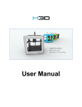
Download RoVa3D User Manual
Transcript
User Manual Rev. B Table of Contents 1. Getting to know your RoVa3D printer .................................................................................................... 5 1.1. What‟s in the box .................................................................................. 5 1.2. Specification ............................................................................................. 6 1.3. What is 3D Printing? ............................................................................... 7 1.4. RoVa3D Overview .................................................................................. 8 1.4.1. Component Names - Front ............................................................................................ 8 1.4.2. Component Names - Back ............................................................................................ 9 2. Getting Started ...................................................................................................................................... 10 2.1. Safety ............................................................................................. 10 2.2. 3D Printing: From Idea to Print .......................................................................11 2.3. Initial setup ..............................................................................................12 2.4. 2.3.1. Tools you will need ...................................................................................................... 12 2.3.2. Connecting the Power Supply ..................................................................................... 13 2.3.3. Installing Filament Guide Tubes .................................................................................. 13 2.3.4. Installing Filament Feed Tubes .................................................................................... 14 2.3.5. Installing Extruder Springs........................................................................................... 14 2.3.6. Installing Filament Spool Holders ................................................................................ 15 2.3.7. Loading Filament ......................................................................................................... 15 2.3.8. Connecting the RoVa3D to your Computer ................................................................. 19 2.3.9. Installing the USB Drivers ............................................................................................ 19 2.3.10. Installing Pronterface / Printrun ............................................................................. 20 2.3.11. Testing Pronterface communication with the RoVa3D ................................................ 21 2.3.12. Installing Slic3r ............................................................................................................ 23 2.3.13. Disabling Windows Update .......................................................................................... 24 2.3.14. Testing the Homing Switches ...................................................................................... 25 2.3.15. Taping the Print Bed .................................................................................................... 28 2.3.16. Leveling the Print Bed.................................................................................................. 31 2.3.17. Leveling Nozzles ......................................................................................................... 36 2.3.18. Setting Z Home ................................................................................................................. 37 2.3.19. Safety Enclosure ......................................................................................................... 39 Basic usage .................................................................................... 44 2.4.1. Choosing a 3D Model .................................................................................................. 44 2.4.2. Slicing Your Model ....................................................................................................... 44 ordsolutions.com 2.4.3. Before Printing ............................................................................................................. 45 2.4.4. Printing Your Model ..................................................................................................... 46 2.4.5. Cool-down ................................................................................................................... 46 2.4.6. Removing Your Model ................................................................................................. 46 2.4.7. Print Examples ............................................................................................................ 46 3. Advanced Usage ................................................................................................................................... 47 3.1. 3.2. 3.3. Multi-Material Printing .................................................................................47 3.1.1. Changing material types .............................................................................................. 47 3.1.2. Ooze prevention .......................................................................................................... 48 3.1.3. Calculating nozzle offsets ............................................................................................ 49 3.1.4. Designing Multi-Material Models ................................................................................. 50 3.1.5. Creating AMF Files ...................................................................................................... 55 Additional RoVa3D Functionality .....................................................................57 3.2.1. Turn LED lights on/off .................................................................................................. 57 3.2.2. Avoid Crossing perimeters .......................................................................................... 57 3.2.3. Vase mode .................................................................................................................. 58 3.2.4. Print bed cover material tips ........................................................................................ 58 3.2.5. Measuring filament diameter ....................................................................................... 59 Pushing the limits................................................................................ 60 3.3.1. Auto PID ...................................................................................................................... 60 3.3.2. Extruder steps per mm ................................................................................................ 63 3.3.3. Advanced Slic3r settings ............................................................................................. 65 4. Keeping things running smoothly ....................................................................................................... 69 4.1. Recommended Service Schedule .............................................................. 69 4.2. Level 1 Service ..........................................................................................70 4.2.1. Multipoint inspection .................................................................................................... 70 4.2.2. Clean the nozzles ........................................................................................................ 70 4.2.3. Clean the filament feed gear teeth ......................................................................... 72 4.2.4. Service the filament feed tube ends ....................................................................... 73 4.2.5. Oil Bearings ................................................................................................................. 74 4.2.6. Oil smooth shafts ................................................................................................... 75 4.2.7. Oil Leadscrews ............................................................................................................ 77 4.2.8. Adjust belt tension ....................................................................................................... 77 4.2.9. Update the firmware .................................................................................................... 78 ordsolutions.com 4.3. 4.4. 4.5. Level 2 Service ..........................................................................................80 4.3.1. Refresh bed printing surface ....................................................................................... 80 4.3.2. Change nozzles ........................................................................................................... 80 4.3.3. Replace Belts .............................................................................................................. 81 4.3.4. Clean fans ................................................................................................................... 84 4.3.5. Service the smooth shafts ........................................................................................... 85 Level 3 Service ..........................................................................................86 4.4.1. Replace Ball Bearings ................................................................................................. 86 4.4.2. Replace Linear Bearings ............................................................................................. 88 4.4.3. Replace filament feed tube .................................................................................... 90 4.4.4. Replace liquid coolant ................................................................................................. 90 Level 4 Service ..........................................................................................93 4.5.1. Replace hot-end heater cartridge ................................................................................ 93 4.5.2. Replace print bed heating element .............................................................................. 93 4.5.3. Replace the smooth shafts .......................................................................................... 94 5. Troubleshooting .................................................................................................................................... 96 5.1. First layer won‟t stick ............................................................................ 97 5.2. Cleaning extruder filament drive wheel ............................................................99 5.3. Clearing Extruder filament guide holes .............................................................99 5.4. Clearing a Jammed Hotend ................................................................... 100 5.5. Clearing a jammed nozzle ........................................................................... 100 5.6. Repairing a popped filament feed tube ........................................................... 101 5.7. Printer won‟t home X/Y/Z ...................................................................... 101 5.8. Bed won‟t heat above X(°C) ................................................................... 102 5.9. Nozzle won‟t heat above X(°C) ..................................................................... 103 5.10. Feedtube end broken off inside quick release ................................................... 104 5.11. If all else fails ......................................................................................... 104 Special thanks to Tim Hedstrom, Joan Touzet, and all of our forum users and Kickstarter backers who have contributed to the body of knowledge incorporated into this manual! ordsolutions.com 1. Getting to know your RoVa3D printer 1.1. What’s in the box List of items: RoVa3D printer 1 power supply with power cord 24” filament feed tubes (one per extruder, one spare) 4” inch long filament guide tubes (one per extruder) USB cable Spool holders Extruder tension screws with springs Filament cleaning wraps Spare quick connects (one male, one female) Optional items: Spare nozzles (0.35mm, 0.5mm, 0.7mm) Maintenance kit Roll of polyimide (Kapton) tape Filament spools ordsolutions.com VIDEO Confirm the contents of your printer box: r1/printer-box-contents 1.2. Specification Printing technology: FDM (Fused Deposition Modeling) / FFF (Fused Filament Fabrication) Print area size: 284 W x 301 L x 191 H mm (11.18” W x 11.88” L 7.55” H) Build volume: Up to print area size, depending on multi- nozzle configuration Layer height: Min 25 microns (0.0009”), Max 1000 microns(0.039”) Print resolution: X: 5 microns (0.0002”) Y: 5 microns (0.0002”) Z: 0.25 microns (0.00001”) Filament Diameter: 1.75mm (0.069”) Nozzle Diameter: Available 0.35, 0.5, 0.7, 1.0 mm (0.014”, 0.020”, 0.028”, 0.039”) Footprint: 280 W x 381 L mm (11” W x 15” L) Overall Dimensions: 665 W x 430 L x 680 H mm (26.18” W x 16.93” L x 26.77” H) Weight: 18.1kg (40 lbs) Shipping box: 711 W x 508 L x 660 H mm (28” W x 20” L x 26” H) Shipping Weight: 24kg (53lbs) without extra items Electrical: Power Supply Input: 115/240VAC, 10A/6A, 50/60Hz Printer Input: 12VDC, 50A (max). Mechanical: Anodized Aluminum, Stainless Steel, Injection Molded ABS Plastic Temperature limits: Operational: 15°C to 30°C, 10-90% RH (non-condensing) Storage: -10°C to 40°C, 5-95%RH (non-condensing) Stepper motors: nd NEMA 17 1.8˚ Step with 1/32 micro stepping Optional “Cool Muscle” Ultra-High-Performance Drive Motors with Closed Loop Vector Control ordsolutions.com 1.3. What is 3D Printing? 3D printing (or additive manufacturing, AM) is any of various processes to make a three-dimensional [1] object. In 3D printing, additive processes are used, in which successive layers of material are laid down [2] under computer control. These objects can be of almost any shape or geometry, and are produced from a 3D model or other electronic data source. A 3D printer is a type of industrial robot. The RoVa3D uses a technology called (FDM) Fused deposition modeling. FDM is an additive manufacturing technology commonly used for modeling, prototyping, and production applications. It is one of the techniques used for 3D printing. FDM works on an "additive" principle by laying down material in layers; a plastic filament or metal wire is unwound from a coil and supplies material to produce a part. VIDEO www.ordsolutions.com/videos/rova3dr1/ how-3D-printing-works Fused deposition modeling: 1. 2. 3. Nozzle ejecting molten plastic Deposited material (modeled part) Controlled movable table Image created by Zureks, used under the GNU Free Documentation License http://commons.wikimedia.org/wiki/File:FDM_by_Zureks.png ordsolutions.com 1.4. RoVa3D Overview 1.4.1. Component Names - Front ordsolutions.com 1.4.2. Component Names - Back ordsolutions.com 2. Getting Started 2.1. Safety High Temperatures Warning: The RoVa3D generates high temperatures at the print head and print surface. Never reach into the print area while the printer is in operation. Always allow the printer to cool down before reaching inside. Keep combustible or flammable materials away from the print head and the print surface. Pinch Points Warning: The RoVa3D includes moving parts that can cause injury. While printing, the extruder gears, print head, and print bed (forwards and back, as well as up and down) will be in motion. Keep hands, clothing, hair, jewelry, and any loose articles clear of moving parts when the printer is on, and ensure that there are no items below the print bed that will interfere when the bed lowers during printing. Fans and Cooling Caution: Before powering on the printer, verify that the fans on the power supply, cooling system, and electrical enclosure are free of obstructions and debris. The RoVa3D will automatically turn on the cooling fans and coolant pump once the coolant temperature is greater than 40°C. After a print is finished, ensure that the printer remains powered until all of the hot ends have cooled to below 50°C. Failure to ensure proper cool down can result in hot end jamming due to filament swelling. Ventilation Caution: During its operation the RoVa3D melts plastic, which can release odors. Ensure the printer is operated in a well-ventilated area. On initial heat-up there may be a small amount of smoke from the nozzles due to oil residue from manufacture. This is normal, and should cease within 30 minutes. Electrical Caution: Maintain easy and clear access to electrical connections, and do not overload electrical supplies. In case of emergency, disconnect the RoVa3D power supply from the wall socket. Lifting Caution: The RoVa3D weighs 40 pounds. Use caution when lifting, and lift with two people if necessary. Always lift by holding the aluminum side panels, or by gripping the threaded rods under the top panel. Never lift directly by the extruder assemblies, aluminum top panel, spool holders, control board case, bed assembly, print head assembly, or x-axis guide rails. Safety Enclosure Caution: To meet safety regulations, the printer must be operated with the safety enclosure installed. See Safety Enclosure section for assembly instructions. ordsolutions.com 2.2. 3D Printing: From Idea to Print 3D Idea Design Software Slicing Software Interface Software Existing Design 3D Idea: The process starts with an idea for a 3D object to print. This part is up to you, and it can be anything from a Yoda head to a part for your new supercar design. Design Software: This is where you create a 3D drawing of your idea. There are many different software options available for designing, both open-source and proprietary. These software packages are often referred to as CAD (Computer-aided Design) software. The output of this software will usually be an .stl file when being used for 3D printing. A popular design software package is Sketchup Make, which is free to use for non-commercial work. Popular commercial software includes SolidWorks and AutoCAD. Existing Design: If you just want to start printing with an existing design, there are thousands of designs available at repository sites, such as thingiverse.com, cubehero.com, and youmagine.com. Slicing Software: Once you have a 3D design (.stl file), it needs to be turned into a machine-friendly file that the printer can understand, called G-code (.gcode file). The slicing software will separate the design into many horizontal layers, which the printer can print one at a time, along with other information such as nozzle and print bed temperatures. This part of the process, along with the interface software and printer firmware, is often referred to as CAM (Computer-Aided Manufacturing). The base configuration files for your ORD printer are designed to be used by a slicing program called Slic3r. If you are new to printing, we recommend that you start with Slic3r (so you can use the base settings we provide), but once your understanding grows, you could try alternative open-source slicing programs such as Cura, or proprietary programs like Simplify3D. Interface Software: The interface software will send the G-code to the printer over the USB connection. The interface software also allows you to manually control the printer; you can move the print head and bed, extrude filament, and set temperatures. The default interface software for your ORD printer is called Pronterface, which is part of an open-source suite called Printrun. There are other interface software packages you can try once you are familiar with Pronterface, or if you use Simplify3D for slicing, it also has built-in interface software. 3D Printing: Once you have setup your printer, and loaded the filament, you can start the print from the interface software. When the printer receives the G-code over the USB connection, the built-in printer firmware will interpret the instructions and send the correct signals to the motors to create your print. ordsolutions.com 2.3. Initial setup 2.3.1. Tools you will need The following are tools you might need to use during the setup or operation of your printer. The items under Maintenance Kit are provided with your printer if you purchased a printer package, or the optional Maintenance Kit. Maintenance Kit Drill Bits: Including micro-bits, these are used for cleaning the nozzles and extruders. Polyimide (Kapton) tape: This is used to cover the bed for enhanced part adhesion. Hex Wrenches: Used for adjusting various components during set-up. 10mm Wrench: To adjust the height of the feed tubes and nozzles. Nut Driver: To adjust various nuts, including the bed-leveling nuts. Digital Caliper: For measuring filament width, printed parts, and parts to be replicated. Feeler Gauges: Used to adjust the nozzle heights. Razor Blade Scraper: Used to remove printed parts from the bed, and to trim the polyimide tape. Side cutters: For trimming filament. Infrared Thermometer: To ensure your heat settings are calibrated. Additional Tools Long nose pliers or tweezers: These are useful to reach under the print heat and remove melted filament, while keeping your fingers at a safe distance. Hobby knife (Exacto or similar): Useful for cleaning up printed items, or scraping melted filament off the nozzles. Scotch-Brite pad: Used for cleaning extruder drive wheels and nozzle tips. 100% Acetone: Used for cleaning the print bed and polyimide tape before printing. Available at paint or hardware stores. Warning: Follow all safety instructions included with the acetone. Paper towels: For cleaning the bed with acetone. Decal squeegee or credit card (old, inactive, or promotional): This can be used this to apply the polyimide tape. Protective safety gloves: These will protect your hands while working on the nozzles and print bed. ¾” Deep Socket (or similar size): This can be used to level the bed and calibrate the nozzle heights. 17mm or adjustable wrench: To hold the heater blocks when replacing nozzles. ordsolutions.com 2.3.2. Connecting the Power Supply 1. Connect the power supply to the printer with the two 6-pin connectors and one 4 pin connector. The small 2-pin connector is unused. 2. Connect the power supply to a wall socket with the supplied power cable. 2.3.3. Installing Filament Guide Tubes Slide the 4 inch filament tube into the bottom side of each extruder. These tubes will help guide the filament from the spool to the extruder. ordsolutions.com 2.3.4. Installing Filament Feed Tubes Connect the 24 inch filament tubes. The tubes are installed in the quick connects by pressing the tube into the connector. The fit can be verified by gently pulling up on the tube after it is installed. Each tube will connect from an extruder to the nozzle quick connect with the corresponding number. To remove the filament feed tubes, press down on the blue ring, press the filament feed tubes down gently, then pull them up and out of the quick release. VIDEO Installing filament feed tubes: r1/installing-filament-tubes 2.3.5. Installing Extruder Springs Install the extruder tension screws with spring and screw head on the same side as the motor, and the nut on the pressure door. Gently press in the bolt head, while holding the extruder door closed, to compress the spring slightly. This will allow you to easily tighten the nut. The nut should be tightened until the spring has approximately 1mm in between each coil. This should leave approximately 10mm of thread protruding beyond the nut. ordsolutions.com 2.3.6. Installing Filament Spool Holders Install the spool holders on the side of the printer by threading each holder into the appropriate hole on the chassis. As shown in the pictures below, two spool holders are installed on the side of the printer below the control box, and three holders are installed on the opposite side of the printer. The jam nut is to remain on the holder before it is threaded into the chassis. 2.3.7. Loading Filament 1. Place a spool of filament onto a spool holder. 2. On each extruder to have filament installed, remove the tension on the extruder door bolts: Gently press the extruder bolts into the springs, while holding the extruder door, and loosen the nuts until the tension is completely removed. 3. Straighten the end of the filament to be installed by gently bending it until it is relatively straight. ordsolutions.com 4. Insert the free end of the filament into the filament guide tube, and up into the extruder. It may be necessary to twist the filament slightly while pushing gently. 5. If you are unable to feed the filament by hand up through the extruder into the filament feed tube, remove the extruder bolt nuts, and open the extruder door. This will allow you to guide the filament into the upper extruder hole past the extruder gear. ordsolutions.com 6. Push the filament through the feed tube 7. Push the feed tube into the quick fitting on the top of the extruder body 8. Guide the filament into the hotend ordsolutions.com 9. Press the feed tube into the hotend quick fitting 10. Replace the extruder pressure bolt nuts and tighten 11. Tie a filament cleaning cloth around the filament where it enters the filament guide tube. This will wipe the dust and debris from the filament before it enters the tube. ordsolutions.com 2.3.8. Connecting the RoVa3D to your Computer 1. Plug the supplied USB cable into the USB port on the front of the electronic box. 2. Plug the other end into a free USB port on the tablet or the computer that will run the printing software. 2.3.9. Installing the USB Drivers The USB drivers are required to allow the computer to communicate with the RoVa3D. NOTE: All the software and configuration files referred to in this manual may also be found If the drivers were auto-installed (Windows 7 or 8) when you connected the USB cable, then you can skip this section. If your printer came with a USB key, it will 1. Go to http://www.ftdichip.com/Drivers/VCP.htm contain all the software and configuration 2. Scroll down the page until you see a table. files. 3. Choose your operating system and the correct If your printer came with a tablet then all the processor architecture. If you don't know your software was installed at the factory, and you architecture you can look it up: may skip the software installation steps. a. Windows: Click the Start button, right click on Computer, and click Properties. The processor architecture (32-bit or 64-bit) is listed under System: System type. b. Mac: Click the Apple symbol at the top left of the screen and click About This Mac. Open the Hardware section to locate the Processor Name. Look up your processor in this table to determine if it is 32-bit or 64-bit: https://support.apple.com/en-ca/HT3696 4. Download and run the appropriate driver version, based on your processor determined above. You may need to be logged on as administrator. 5. Follow the steps in the installer, and reboot your machine. ordsolutions.com 2.3.10. Installing Pronterface / Printrun Pronterface is the program that will provide the interface to your printer. 1. Go to http://koti.kapsi.fi/~kliment/printrun/ 2. Download the newest .zip file for Mac or Windows. 3. There is no installer program for Pronterface. Extract the files into c:\Program Files\ and create a shortcut to pronterface.exe on your desktop. 4. Copy the preset file „printrunconf.ini‟ from the USB drive to C:\Users\<YourUserName> ordsolutions.com 2.3.11. Testing Pronterface communication with the RoVa3D Pronterface Overview – Left Side ordsolutions.com Pronterface Overview – Right Side 1. 2. 3. 4. Testing Communication Open Pronterface using the shortcut. (Printrun is what is shown on Macs) Change the baud rate to 250000 Select the Port that the RoVa3D is connected to. a. Click the Port button to scan for open ports. The RoVa3D will typically be the highest port number shown. b. If you are unable to determine which port the RoVa3D is connected to, run Device Manager, expand Ports, and look for the COM port assigned to the last entry of „USB Serial Port‟ Click the Connect button and wait for it to connect to the RoVa3D. After a successful connection to the RoVa3D, you will see the firmware settings displayed in the right side window of Pronterface. ordsolutions.com 2.3.12. Installing Slic3r 1. Move the Slic3r folder from the supplied USB Thumb drive to „C:\Program Files\Slic3r‟. This folder contains both Windows and Mac, and 32-bit and 64-bit versions. Additionally, for each computer type, there are two versions of Slic3r, 1.1.7, and the latest experimental version, which is currently 1.2.6. Both versions will be required to enable multi-material printing. a. Slic3r 1.1.7 contains the capability of combining multiple .stl files into an .amf file, which will be required to print multi-material printing. This is the only task which Slic3r 1.1.7 will be used for. b. Slic3r 1.2.6 is an „Experimental‟ release, but has been found to be stable, and contains all the newest features. This is the version which should be used for all tasks except creating .amf files. 2. Move the „Slic3r‟ folder from the „Slic3r config‟ folder files to „C:\Users\<YourUserName>\AppData\Roaming\Slic3r‟ 3. Create a shortcut from each slic3r.exe (Both 1.1.7 and 1.2.6, where you copyed the files in step 1) to your desktop. Rename them to show the correct version number. 4. Run Slic3r 5. To access the multi-extruder options, Slic3r needs to be switched to Expert Mode. You will only need to do this once (for each computer you install Slic3r on). To enable Expert Mode, go to File/Preferences. Change the Mode from Simple to Expert. Click OK. You will be prompted to close Slic3r and reopen it for the change to take effect. ordsolutions.com 2.3.13. Disabling Windows Update If Windows Automatic Updates initiates during a print, it could cause the prints to fail. To disable Automatic Updates (for Windows 7), go to: Control Panel -> Windows Update -> Change Settings -> Select „Download updates but let me choose whether to install them‟ . ordsolutions.com 2.3.14. 1. 2. 3. 4. Testing the Homing Switches Ensure Pronterface is connected to the RoVa3D. Click the „Motors off‟ button in the top left of Pronterface. Gently push the X carriage to the middle of the RoVa3D. Gently push the Y carriage (print bed) to the middle of the RoVa3D. 5. Press the +Z 10 button until the print bed is low enough that the homing flag is below the sensor 6. Click the button marked „Optos‟ in Pronterface. 7. Ensure that the response in the Pronterface commands window shows: Reporting endstop status x_min: open y_min: open z_min: open 8. If any of the reported sensor status show TRIGGERED, contact Support for assistance. 9. Push the X carriage all the way to the left so that the opto flag is in the opto sensor. ordsolutions.com 10. Push the print bed all the way towards the rear of the printer so that the Y opto flag is in the Y opto sensor. 11. Pull the entire Z assembly up so that the Z opto tab is in the Z opto sensor. 12. Press the „Opto‟ button in Pronterface. ordsolutions.com 13. Ensure that the response in the Pronterface commands window shows: Reporting endstop status x_min: triggered y_min: triggered z_min: triggered 14. If any of the opto sensors are not triggered please contact support 15. Once the opto sensors are confirmed working, press the „Home All axis‟ button in Pronterface 16. Confirm that the Bed is within 5mm of the nozzles once its homed 17. If the nozzles are not within 5mm of the print bed when homed: a. Loosen the Z opto sensor threaded rod nuts and slightly raise the height of the opto sensor. b. Tighten the nuts. Ensure that the opto sensor is lined up with the opto flag so that when the bed is raised, the flag will pass through the sensor. c. Click Z+10 in Pronterface. d. Click Home Z in Pronterface. e. Repeat as needed until the bed homes within 5mm of the nozzles. ordsolutions.com 2.3.15. Taping the Print Bed Before printing, the bed must be covered with a material that can be printed on. The print bed is made of anodized aluminum, and no print materials will adhere to it directly. While there are several different types of bed coverings, it is recommended to start with polyimide (Kapton tape). Different options are discussed in „Print bed cover material tips‟ in the Advanced section. Polyimide tape will be included with the RoVa3D if you ordered a Maintenance Kit, or you can order it directly from ORD Solutions. While the tape can be applied directly to the bed and smoothed out with your thumb, it can be very difficult to apply it in this manner without getting bubbles. While the bubbles can be later pierced with a pin and the tape smoothed out, the soap method detailed below can give very good bubble-free results. Soap method 1. Remove any old tape on the bed. 2. Clean the bed with pure acetone or rubbing alcohol (minimum 90%, best is 99%), and a paper towel. 3. Put water into a small bowl. 4. Put a generous amount of plain dish soap into the water (from one to three teaspoons). 5. Mix the soap into the water. ordsolutions.com 6. Using a clean paper towel, spread a thin layer of soapy water on the print bed. There should be enough soap in the water that the soapy film is uniform, and not „beading up‟. 7. Cut the polyimide tape into strips that are slightly longer than the print bed. 8. Lay the tape strips on the print bed so that the edges touch. ordsolutions.com 9. Using a plastic card, squeegee the tape so that the soapy water is removed from under the tape. 10. Allow the tape to dry. This can be sped up by heating up the print bed. You may want to continue smoothing down the tape with the plastic squeegee while the tape is drying. 11. Once dry, use a razor blade to cut off any excess tape at both ends of the print bed. ordsolutions.com 2.3.16. Leveling the Print Bed The bed is leveled before shipping; however the leveling should be verified before using your RoVa3D. The bed adjustment screws are located on the underside of the Y carriage. You will need a deep ¾” socket (or similar size). This will be used as a gauge block to allow easier measurement of the gap between nozzles and the bed. Place a mark on the top of the socket, as shown in the picture below, to ensure that you are always measuring to the same spot on the socket. ordsolutions.com Level the bed to these 3 points. You will put the socket over each of these points in turn and level the bed to the socket and the tip of Nozzle 5. To level the bed please follow these instructions: 1. Home the print bed by pressing the „Z home‟ button in Pronterface ordsolutions.com 2. Press the +10 Z button several times in Pronterface to create enough space for the socket to be between the nozzles and the print bed 3. Put the socket on the bed 4. Push the Z -1 button to bring the socket closer to the nozzle ordsolutions.com 5. Move the socket and nozzle over the first leveling spot 6. Manually turn the „Z stepper knob‟ to bring the nozzle tip to touch the surface of the socket 7. Move the socket and nozzle to the next leveling spot ordsolutions.com 8. Reach under the printer and adjust he respective „bed adjustment screw‟ to move the print bed until it skims the surface of the socket rd 9. Move the socket and nozzle to the 3 leveling spot ordsolutions.com 10. Reach under the printer and adjust he respective „bed adjustment screw‟ to move the print bed until it skims the surface of the socket 11. Repeat steps 6 to 11 to confirm print bed level 2.3.17. Leveling Nozzles The nozzles are held into position with two nuts located on the threaded barrels at the top of the printer. These nuts are all 10mm in size. The nuts have a 1mm pitch which makes adjustment very easy, for th example, to adjust the height by 0.1mm turn the nut 1/10 of a turn. Always level the nozzles as close to the center of the print bed as possible. You will need a deep ¾” socket (or similar size). This will be used as a gauge block to allow easier measurement of the gap between nozzles and the bed. Place a mark on the top of the socket, as shown in the picture below, to ensure that you are always measuring to the same spot on the socket. ordsolutions.com To adjust the level of the nozzles follow these steps: 1. Position the socket under the nozzle to be adjusted 2. If the nozzle is too close to the socket, loosen the nut below the top plate of the nozzle cart then tighten the top nut until it is snug. 3. If the nozzle is too far from the socket, loosen the top nut then tighten the bottom nut until snug. 2.3.18. Setting Z Home The Z Home location must be set correctly to ensure that the bed is at the correct height from the nozzles. This will ensure that your first printing layer will be correctly created, and that the bed won‟t contact the nozzles. Prior to homing the Z axis - Always lower the bed until the opto stop tab is below the opto sensor. Failure to do so could result in the bed hitting the nozzles! This blog entry details the concept of using M206: code-m206/ 1. Ensure the bed is leveled. 2. Ensure the nozzles are either leveled (if using all 5 nozzles), or that nozzle 1 is even or lower than the other nozzles (if you are only printing with one nozzle). 3. Connect to the printer with Pronterface. ordsolutions.com 4. Press +Z 10 to ensure that the Z flag is lower than the Z opto sensor. 5. Press Home Z 6. Verify that when homed, the print bed is less than 5mm from the nozzles. If not: a. Adjust the wing nuts on the threaded rod holding the Z opto coupler to raise the coupler slightly. b. Press Z+10, then Z Home. c. Verify that the distance between the bed and nozzles if now less than 5mm. If not, go to step a and repeat until within 5mm. 7. In Pronterface manually adjust the bed closer using Z-1 and Z-0.1, until the nozzles are 0.2 to 0.3mm away from the bed. You can use the feeler gauges from the Maintenance Kit for an exact measurement, or use 2-3 pieces of standard 20lb paper. 8. Count the distance with each button click, until the. are the correct distance away. Eg. If you pressed Z-1 3 times, and Z-0.1 four times to bring the bed to the correct distance from the nozzles, you would have counted 3.4mm. ordsolutions.com 9. Enter „M206 Z<your counted mm>‟ into the box in Pronterface. (Eg. In the example above, you would enter: M206 Z3.4 10. Press the „Send‟ button 11. Press the „Save‟ Button 12. Press the „Show‟ Button to check your changes Now when Z Home is commanded (by button, or by software prior to a print), the print bed will move to the opto stop level, and 3.4mm beyond. This will put the bed at the correct height to print the first layer. 2.3.19. Safety Enclosure Your RoVa3D printer has some safety hazards that require care and caution if you want to avoid injury. For safety requirements, it is necessary that you assemble the printer enclosure and attached it to the printer. You must always lock the enclosure and ensure it is secured to the printer properly during use. Never operate the printer with the enclosure removed or the door open or unlocked. To assemble the enclosure you will require the following tools: 1) 2) 3) 4) 5) Work gloves Black Robertson screw driver #3 Adjustable wrench Adjustable pliers Optional drill with #3 Robertson bit To assemble and mount the enclosure please follows these steps: ordsolutions.com Assembling back section 1) Screw the 600mm support to a top panel. 2) Attach the 2x 450mm and 1x 380mm support to the back panel. 3) Attach the top panel and side panel to the back panel. ordsolutions.com Assembling front section 1) Assemble the door and attach to the door panel. 2) Attach 2x 450mm supports to the door panel and attach the side panel. 3) Attach the other side panel and the top panel. ordsolutions.com Install enclosure on printer 1) Remove the spool holders from the printer. 2) Remove the nuts from the spool holders. 3) Slide the back half of the enclosure onto the printer. Ensure that the 600mm support is routed under the liquid cooling lines and over the X-carriage electrical wires. 4) Screw the spool holders through the case into the X Side Plate. ordsolutions.com 5) Slide the front half of the enclosure onto the printer and screw the spool holders in. Ensure that the 600mm shafts go under the opposing top panels. 6) Gently press the top of the case halves together and screw the top panels to the 600mm supports. 7) Screw the side panels to the 600mm supports. ordsolutions.com 2.4. Basic usage 2.4.1. Choosing a 3D Model You will eventually want to create your own 3D designs, but to get started there are many existing designs on the web. You can find thousands of designs available at repository sites, such as thingiverse.com, cubehero.com, and youmagine.com. For a test print, you can download the 40mmTestCube.stl file from www.ordsolutions.com/3d-printexamples This object is simple and relatively small. If you watch the printing process, you will start to learn about the process the printer uses to make the print. This is important in later more complex prints, as understanding how the printer operates will help to highlight where printing improvements can be made. 2.4.2. Slicing Your Model 3D models are solid objects. The 3D Printing process lays down molten plastic layer by layer. This requires a „sliced‟ version of your 3D model. One in which your 3D model is sliced into each layer that will be printed. These slices contain all the information your printer needs to know, including where to move the hotend nozzles for every sliced layer, how fast to move, and how much plastic to extruder with every movement. The program that creates the sliced version of the 3D model is colloquially referred to as a „slicer‟. The slicer that we recommend, and that comes pre-configured for your printer, is called Slic3r. To slice your 3D model in preparation for printing please follow these steps: 1. 2. 3. 4. 5. 6. 7. Open Slic3r. Select „Med Resolution‟ in the print settings. Select „Off‟ for each of the filaments (this will allow manual temperature control in Pronterface). Drag and drop your .stl object onto the layout area. Click „Export G-code…‟ Select the a location for the sliced g-code file Press „Save‟ ordsolutions.com 2.4.3. Before Printing In order to print with your new 3D Printer you will need a printer control program. There are many different options for a printer control program; however the program we recommend for your ORD Solutions 3D Printer is called „Pronterface‟. It is very intuitive and easy to use. In the slicing example above, we selected OFF for the filament in Slic3r. This allows us to manually control the temperature in Pronterface. For later prints, you can select your filament type in Pronterface, and the printer will automatically heat up to the recommended temperature before printing. Clean the bed You can clean the bed while it is warm or cold. If you clean it while it is warm, the acetone will evaporate more quickly, but wear protective gloves and be careful of the hot surface. 1. Using Pronterface, Home Z, then lower the bed 100 millimeters. 2. Dampen a clean cloth or paper towel with pure acetone. 3. Wipe the print bed with the cloth from the back to the front. Continue wiping from back to front in stripes until you have wiped the entire bed. 4. Switch to a clean portion of the cloth or paper towel, and repeat, using more acetone if necessary. Continue repeating until you are not seeing any more dirt on the cloth. Warm up the hot end and bed 1. Open Pronterface 2. Press Connect (ensure your correct port is set) 3. Select the temperature for the hot end and bed: a. If you are printing with PLA, select 200 for Heat, and 88 for Bed. Click Set on each. b. If you are printing with ABS, select 230 for Heat, and 130 for Bed. Click Set on each. ordsolutions.com 4. Wait for the RoVa3D to heat the bed and nozzle. You can see the current set points and temperature in the graph, and in the line of text below. The numbers beside „T:‟ are your currently selected hot end temperature and set point. The numbers beside „B:‟ are your current bed temperature and set point. 2.4.4. Printing Your Model Since you have already sliced your first 3D model please follow these steps to begin your first 3D Print: 1. Load the sliced gcode file for your sample 3D object. 2. Wait for the temperature to stabilize. 3. Prime the nozzle by clicking „Extrude‟. Continue extruding until you see some filament come out of the nozzle. Discard the extruded filament with tweezers or pliers. 4. Press the „Home‟ button (the white home button to the lower left of the bullseye). 5. Press the „Print‟ button. 6. As the skirt prints on the object, you can micro adjust the print bed distance to the nozzle by turning the Z stepper knob. 7. Observe the printing properties in Pronterface. 8. Observe the printer while printing your object. 2.4.5. Cool-down Once the print has finished the printer will home the X & Y Carriages. It will also set the temperature to zero for the print bed and any nozzles that were turned on for the print. Allow the print bed to cool to room temperature before attempting to remove the printed object. 2.4.6. Removing Your Model The object will be much easier to remove once the print bed temperature has returned to room temperature. Gripping the object gently with your fingers and prying gently in a side-to-side motion should unseat the object. If this doesn‟t work, a flat razor blade can be used to gently pry around the edges of the part until it pops off (wear protective gloves). You have completed your first 3D print! 2.4.7. Print Examples Go to www.ordsolutions.com/3d-print-examples for some 3D examples that you might want to try printing. ordsolutions.com 3. Advanced Usage 3.1. Multi-Material Printing 3.1.1. Changing material types Your ORD Solutions 3D printer is able to print a wide array of materials. These materials may have different properties, including widely varying melting temperatures. If it‟s the first time you have loaded filament into a particular hotend, then simply load the filament as normal. If you are loading a filament with a different melting point (but within 30°C), you will need to prime the nozzle at the higher temperature of the two melting points. If you are loading a different material with a melt temperature which is more than 30°C different than the previous filament, you will need to use a transition material in between them. Follow the appropriate section below to change filament materials. New material has the same melting point (different colour): 1. Remove the tension from the extruder door springs. 2. Disconnect the filament feed tube at the hotend. Remove the filament from the hot end by pulling out the filament by hand. If it does not come out easily, heat the nozzle to the melting temperature of the material, and then pull out the filament. 3. Load the new filament, reconnect the filament feed tube and extruder pressure door springs, and extrude manually until none of the old colour is coming out of the hot end. New material has a higher melt temperature (within 30°C): 1. 2. 3. 4. 5. 6. Heat the hotend to the lowest melt temperature of the higher temperature material. Cut a length of filament from the new material spool 24” long. Remove the filament feed tube from the hotend that will be used. Push the new material into the hotend by hand. Feed the filament into the hotend until the old material is replaced with the new material. Set the temperature to the proper setting for the new filament. New material has a lower melt temperature (within 30°C): 1. 2. 3. 4. 5. 6. Heat the hotend to the highest melt temperature of the new lower temperature material. Cut a length of filament from the new material spool 24” long. Remove the feed tube from the hotend that will be used. Push the new material into the hotend by hand. Feed the filament into the hotend until the old material is replaced with the new material. Set the temperature to the proper setting for the new filament. New material has a higher melt temperature (greater than 30°C difference): 1. Heat the hotend to the lowest melt temperature of the next higher (intermediate or final) temperature material. 2. Cut a length of intermediate filament (melt temperature within 30°C) 24” long. 3. Remove the feed tube from the hotend that will be used. 4. Push the new material into the hotend by hand. 5. Feed the filament into the hotend until the old material is replaced with the new material. ordsolutions.com 6. Heat the hotend to the lowest melt temperature of the next higher (intermediate or final) temperature material. 7. Repeat for each transition material needed for each 30°C step in melt temperature. 8. Once you have primed the nozzle with the final filament, set the temperature to the proper setting for the new filament. If the new material has a lower melt temperature (greater than 30°C difference): 1. 2. 3. 4. 5. 6. Heat the hotend to the melt temperature existing material. Cut a length of intermediate filament (melt temperature within 30°C) 24” long. Remove the feed tube from the hotend that will be used. Push the new material into the hotend by hand. Feed the filament into the hotend until the old material is replaced with the new material. Reduce the temperature of the hotend to the melt temperature of the new (intermediate or final) material. 7. Repeat for each transition material needed for each 30°C step in melt temperature. 8. Once you have primed the nozzle with the final filament, set the temperature to the proper setting for the new filament. 3.1.2. Ooze prevention Enabling this option will cause a high skirt to print around the object. During the tool changes (when switching to different colors or materials) the nozzle will be parked outside the skirt while it cools down and then wiped across the skirt to keep the oozing strings on the outside of the skirt. After the print is complete the skirt may be disposed of. ordsolutions.com 3.1.3. Calculating nozzle offsets Because each of the nozzles is in a different location, in relation to nozzle 1, the printer needs to „know‟ the offset from nozzle 1 for each of the other nozzles. When the „T‟ tool change command is issued the printer will move the offset distance thereby positioning the next nozzle over the correct area to be printed. In order for the nozzles to be positioned correctly on a multi material print their offsets must be determined very accurately. Each printer will have slight variations in the position of the nozzles. To get the most out of your printer you will need to calculate the exact nozzle offsets for your printer by following these steps: 1. Download the Nozzle Offset Calculation object from www.ordsolutions.com/3d-print-examples or locate it on your tablet or USB drive. 2. Slice the Multi_Head_Calibration .amf file with Med resolution. a. If only selected heads are to be calibrated, you can combine the appropriate .stl files into an .amf file according to the directions in the „Creating AMF Files‟ section of the manual. 3. Print the object. 4. Calculate the differences according to the following illustrations and where the gap is on the print: 5. Update the settings 6. Re-slice 7. Print again 8. Repeat until there are no gaps ordsolutions.com Calculating nozzle offsets flowchart 3.1.4. Designing Multi-Material Models Multi material or multi-color printing requires a model with multiple parts. The simplest way to make a multi body part is to cut an existing model into segments and combine it into an AMF file. There's no shortage of single material models out there. With a little creativity, you can modify these single material models to make multi-material models that build on and enhance the originals. You can download Netfabb Basic for free from their website: http://www.netfabb.com/basic.php. Once installed, run it, and after agreeing to their Terms of Usage, you will be brought to their main window. Start by opening a single material model by selecting: Project --> Add Part and then choosing an .stl file. ordsolutions.com We're using a customized Minecraft sword by YoloMcSwaggins as our model. By default, this model is placed on the print bed on the diagonal, probably so that it fits on smaller beds. In order for us to cut it down the middle, we need to rotate it so that it is aligned with the print axis. With the whole model selected, use this command: Part --> Rotate We need to rotate the part along the Z axis by 45 degrees, as shown in this dialog: ordsolutions.com Click the Rotate button and now the part can be cut along the X axis. (If we had rotated it by -45 degrees, then we would be cutting it along the Y axis.) Once the model is positioned how we want it, you use the Cut tool to split the model into two or more pieces. Using this technique, you can only divide the model along the X, Y, or Z axes, but that still gives you a lot of flexibility, especially when you combine the Cut tool with the Rotate tool. To cut it along the X axis, click the middle of the box beside the "X" in the "Cuts" section to the right. ordsolutions.com Depending on the value in the slider, a red line will appear somewhere in your model. Drag the slider to position it where you want the cut. You can use your right mouse button and manipulate the model to examine it from all sides to confirm that you have positioned the cut where you want it. Click the "Execute cut" button to perform the cut. A new "Cut" button appears at the bottom. Click the "Cut" button and you've completed the cut. ordsolutions.com Once you've completed the Cut, your model now consists of two parts. You need to export each of these parts as separate STL files. Select one of the parts, and use the command: Part --> Export Part --> as STL (ASCII) Select the second part and export it the same way. You can split the model into any number of pieces, and then multi-select several parts to have them exported as a single STL file for printing purposes. Once you have your STL files, follow the instructions in the „Creating AMF Files‟ section below to combine your STL files into a single AMF file. ordsolutions.com 3.1.5. Creating AMF Files Step 1: In the modeling tool of your choice, separate your object into multiple pieces. You can follow the steps in the „Designing Multi-Material Models‟ section above. Make sure that each piece has the same origin, and touches but does not overlap any of the other pieces. If one object is all or partially inside another object, than the first object must have a gap that corresponds to the second object. Then export each piece as a separate .stl file. Step 2: Combine these files in Slic3r to create an .amf file. In Slic3r go to File/Combine multi-material STL files. In the Open dialog, select the first .stl file and click Open. A new Open dialog will appear, select the second file and click Open. A third Open dialog will appear, and so on. Once you have added the last file, click Cancel in the next Open dialog. A Save As dialog will appear. Type a new name for the combined file and make sure it has the extension .amf. If .xml appears replace it with .amf. Click Save. Note: There are two versions of Slic3r required: 1.1.7, and the latest experimental version, which is currently 1.2.6. Both versions will be required to enable multi-material printing: 1. Slic3r 1.1.7 contains the capability of combining multiple .stl files into an .amf file, which will be required to print multi-material printing. This is the only task which Slic3r 1.1.7 will be used for. 2. Slic3r 1.2.6 is an „Experimental‟ release, but has been found to be stable, and contains all the newest features. This is the version which should be used for all tasks except creating .amf files. Step 3: To print with this new file, you "Add" the .amf file to Slic3r just as you would a .stl file. To see the combined object, click the Settings button on the Plater tab. You can click and drag on the object to rotate and see it from all sides. Step 4: Assign each objects to an extruder in Slic3r 1.2.6 and export the g-code. 1. Click the Settings button. 2. Select the first object. 3. Verify that the correct extruder is selected in Part Settings -> Extruders. Repeat for each object in the object list. 4. Click OK, then click Export G-code ordsolutions.com ordsolutions.com 3.2. Additional RoVa3D Functionality 3.2.1. Turn LED lights on/off The bed lighting LEDs can be turned off using the LED ON or LED OFF buttons in Pronterface. They can also be turned on and off using g-code: Light on is M101 S1 Light off is M101 S0 3.2.2. Avoid Crossing perimeters Enabling this option will reduce strings and oozing but dramatically increases the time required to slice the model. ordsolutions.com 3.2.3. Vase mode Enabling the vase mode will print the object with only a single perimeter, no infill, and no top solid layers. The advantage is that Print bed will be lowered continuously while printing the perimeter in a continuous spiral, thus, avoiding the „seam‟ usually present in other prints. 3.2.4. Print bed cover material tips This section will give you tips for the various materials used for your RoVa3D's bed. Kapton Tape (Polyimide Tape): Kapton tape must be free of grease. Clean it with 100% acetone before each print. This material works for both ABS and PLA prints. You can use „ABS Juice‟ (see below) before a print with ABS to help it stick to the bed. Blue Painter's Tape: Do NOT heat the bed with this material. Don't overlap the edges or miss any spots. You can clean this material with alcohol. Replace when damaged or adhesion starts to degrade. Usually, 5-10 prints. Can be used for PLA, ABS, and Nylon. A coating of Elmer‟s glue stick (or similar) is optional to help the part adhere. Glass: A sheet of glass can be cut to the same size as the bed, and held on with binder clamps. ordsolutions.com Works well for PLA printed with bed temp of 70. A coating of Elmer‟s glue stick (or similar) is optional to help the part adhere. Use ABS Juice (see below) on the bed to help ABS adhere. 'ABS Juice': „ABS Juice‟ is a mixture of acetone with some ABS dissolved in it. Start with about a cup of acetone, and a foot or two of ABS, cut into little strips. Either use natural colour ABS, or the colour of the part that you're going to print with. Put them in a bottle, and let the ABS dissolve. This will take from several hours to overnight. You can help the process along by giving the bottle a shake once in a while. You are looking for consistency thicker than water, but less than milk. If you get to cream or yogurt consistency, add some acetone to dilute it. Once you have your 'ABS juice', warm up your bed and just before you print, wipe some juice on the bed with a folder paper towel or a cotton ball. Be careful not to get it on the print heads. And be sure not to have any open flame around when you're applying the juice. 3.2.5. Measuring filament diameter To get the best surface finish it is important to use the actual diameter of the filament in the slicing program. This is because the slicing software is calculating the amount of filament that must be extruded to fill the volume of each layer. Since the diameter of the filament determines what volume of material is extruded for each mm pushed out it. Even though the filament you have purchased is listed as 1.75mm it may vary in diameter by as much as +-0.1mm and be between 1.65mm and 1.85mm in diameter. Generally it is better to have a lower diameter (ie. 1.65 is better than 1.85mm). The best filament diameters vary by <0.05mm. 1. 2. 3. 4. Use digital calipers Measure perfectly perpendicular to the filament Use the knife tips of the calipers to gently grip the filament Measure every 2 inches over a total length of 12-24 inches ordsolutions.com 5. Average the result of the measurements 6. Create a new filament profile in silc3r and enter the value you calculated for the diameter. 3.3. Pushing the limits 3.3.1. Auto PID Maintaining the correct temperature is critical for the quality of printed parts. The smaller the temperature fluctuation during printing the better the surface finish quality of the completed part will be. Temperatures should stay in the +/-1°C range from the set temperature during printing. The method the printer uses to control the temperature is called „PID‟. Though PID is a very sophisticated algorithm, setting the correct values is easy with the automatic PID function built into your printer. To get the most out of your machine you should periodically calculate the PID values for the hotend and the print bed. To calculate the PID values for the hotends, perform the following steps: 1. Connect to the printer 2. Power on the printer 3. Enter the command „M303 S<desired temp>‟ where <desired temp> is the actual temperature you want to be accurately maintained 4. Wait for the PID function to run ordsolutions.com 5. Into the command box enter „M301 P<P Value> I<I Value> D<D Value>‟ where the <value> is the nd actual value displayed in Pronterface from the 2 PID value set. 6. Press the „Send‟ button 7. Press the „Save‟ button 8. Enter the M301 command from step 5 into your start G-code in Slic3r (Printer Settings -> Custom G-code -> Start G-code). ordsolutions.com To calculate the PID values for the print bed, perform the following steps: 1) Connect to the printer 2) Power on the printer 3) Enter the command „M303 E-1 S<desired temp>‟ where <desired temp> is the actual temperature you want to be accurately maintained 4) Wait for the PID function to run 5) Into the command box enter „M304 P<P Value> I<I Value> D<D Value>‟ where the <value> is the actual value displayed in Pronterface for the „some overshoot‟ PID value set. 6) Press the „Send‟ button 7) Press the „Save‟ button 8) Enter the M304 command from step 5 into your start G-code in Slic3r (Printer Settings -> Custom G-code -> Start G-code). ordsolutions.com 3.3.2. Extruder steps per mm The printing of a 3D object is accomplished by the extrusion of molten plastic into a shape. The shape is built up one layer at a time. Because each segment of every layer represents a tiny volume that needs to be filled, the exact extrusion of filament is critically important to getting the best out of your printer. If the printer extrudes too much material volume then that will lead to strings and blobs and uneven wall surfaces. If the printer extrudes too little then it will cause inconsistent flow, broken strands, gaps, and uneven coloring. The extruder comes calibrated from the factory for the correct steps per mm of extruder filament feed, however, it is a good practice to confirm the correct settings for your printer as there could be some minor variance from one printer to the next. To calculate the steps per millimeter of extruded filament please follow these steps: 1. Connect to the printer 2. Power the printer on 3. Set the hot end temperature for extruder 1 to the correct temp for the currently loaded filament tube (i.e. 200 for PLA) 4. Once the temperature is reached, press the quick release blue ring down, push down gently on the feed tube, then pull the feed tube up and out of the quick release. 5. Use a straight razor to cut the filament off flush to the end of the filament feed tube 6. Set the extrusion distance in Pronterface to 50mm 7. Set the extrusion speed to 200mm/m in Pronterface 8. Press the extrude button ordsolutions.com 9. Cut the filament off at the feed tube end 10. Measure the filament extruded 11. Using the „Extruder steps per mm calculation.xls‟ spread sheet (available at www.ordsolutions.com/extruder-calibration ) calculate the new value. 12. Copy and paste cell „D‟ into Pronterface 13. Send & save the new value 14. Repeat this process 5x for accuracy 15. Replace the filament feed tube into the hotend quick release ordsolutions.com 3.3.3. Advanced Slic3r settings In Slic3r so far we have used the supplied default settings from ORD Solutions. But to push the limits of the printer‟s capability it will require trial and error and fine tuning of the printer and the Slic3r settings. Let‟s discuss some concepts here. The length of time it takes to print and object is mostly affected by the layer height and the size of the object we wish to print. Observe the chart below: First, we should understand that the lower the layer height the more difficult it is to extrude filament. The smaller the nozzle orifice the more difficult it is to extrude filament. These 2 factors determine the maximum speed that we can print before the filament will strip at the extruder or jam in the hotend. Therefore increasing one or both of them is the way to faster print speeds. However, there is a limit to both factors. We only supply nozzles with an orifice diameter up to 1mm. The limitation will be that all corners will have a radius of .5mm and won‟t look very „square‟. We can‟t go bigger because the filament is only 1.65mm in diameter minimum and so wouldn‟t melt reliably if the orifice were larger. The maximum layer height is determined to be equal to the nozzle orifice. See the chart below for the min/max layer heights of each nozzle by orifice size: Layer Nozzle Min Max 0.10 0.20 0.025 0.025 0.100 0.200 0.35 0.50 0.025 0.025 0.350 0.500 0.70 0.100 0.700 1.00 0.300 1.000 The lower the layer height the „higher‟ the resolution of the print. This means that the higher the resolution, the more difficult it is to visually see the layers of the print. The smaller the layers, the closer the printed parts will resemble an injection molded piece. However, the time required to complete higher resolution prints scales linearly with layer height (i.e. half the layer height will take twice as long). ordsolutions.com The close up on the left in the picture above compares a 400 micron layer height to a 200 micron layer height. If you look closely, you can see that there are 7 layers in the tentacle on the left and 14 layers in the tentacle on the right. The close up on the right compares the 200 micron layer height to the 100 micron layer height. Because the layer height is halved in the 100 micron print, the layers tentacle are doubled again to 28. When handling these prints, you can definitely notice a ridged feel on the 400 micron layer print. The 100 micron layer print feels smooth. It's only if you drag your fingernail across the print that you can tell that the object is made up of individual layers. Here's another print comparison: ordsolutions.com It is clear that the results of a lower layer height are preferable. We recommend you start with higher layer heights for the rough draft of the prints and when you are first starting out. Once you have some experience printing and need better quality for display or demonstration purposes then reduce the layer heights. For the large white octopus above with a 600 micron layer height, a .7mm nozzle was used. It‟s not possible to print an object with a layer height greater than the nozzle diameter, so this print would not be possible with a .5mm or a .35mm nozzle. You can, of course, print an object this size with a smaller layer height, and sometimes you will want to. We have a Yoda that was printed at 100 microns with a .5mm nozzle. It took over 30 hours, and it looks amazing! In person, you cannot see the individual layers due to Yoda's skin pattern. This is one of our favorite prints. Having a .7mm nozzle on your printer gives you a lot of flexibility to do fast prints at large layer heights to test your model's printability. Then, when you've optimized your model, you can switch to a lower layer height for your final print. When adjusting the layer height it must be a multiple of .025 otherwise there may be inconsistent layer thicknesses. (eg. Correct: 0.125 - Incorrect: 0.135) ordsolutions.com ordsolutions.com 4. Keeping things running smoothly The recommended service schedule is designed to keep your RoVa3D printing at its optimum performance, and is based on a usage of 50 hours per week. Each service level includes all the lower levels (i.e. when a Level 3 Service is performed, also perform a Level 1 and Level 2 Service). 4.1. Recommended Service Schedule Level 1 Multipoint inspection Clean the nozzles Clean the filament feed gear teeth Service the filament feed tube ends Oil Bearings Oil smooth shafts Oil Leadscrews Adjust belt tension Update the firmware Level 2 Refresh bed printing surface Change nozzles Replace Belts Clean fans Service the smooth shafts Level 3 Replace Ball bearings Replace linear bearings Replace filament feed tube Replace liquid coolant Level 4 Replace hotend heater cartridge Replace print bed heating element Replace the smooth shaft ordsolutions.com 4.2. Level 1 Service 4.2.1. Multipoint inspection During the multipoint inspection, a general checkup of the printer should be made. At a minimum, the following items should be checked: X-frame threaded rod nuts tight Y-frame threaded rod nuts tight Carriage motion smooth and quiet (X, Y) Carriage has no binding from edge to edge travel (X, Y) X carriage belt stays on the bearings and pulley after 10X edge to edge pushes Y carriage belt stays on the bearings and pulley after 10X edge to edge pushes X, Y, Z tension bearing screws are tight Minimal backlash between large and small extruder gear (all extruders) Stepper motor screws tight (X,Y,Z, all extruders) Extruder pressure bearing spins smoothly and freely (all extruders) Belt tension consistent and tight enough to prevent tooth skipping (X, Y, Z) No up/down play in the Y Assembly lead screw/pulley X opto flag nut tight Y opto flag nut tight Z opto flag nut tight Smooth shaft set screws are tight (X, Y, Z) Zip ties are present and tight on all barbs and fittings Coolant level is topped up Print bed is level All nozzles are leveled to the print bed Z opto sensor threaded rod nuts are tightened Hotend jam nuts are tight (H1,2,3,4,5) Hotend ceramic insulation covers the entire circumference of the hotend heater (all hotends) Hotend fiberglass insulation covers the entire length of the ceramic wool (all hotends) 4.2.2. Clean the nozzles A micro drill bit (also known as PCB drill bits) in the correct size is required. Here are the sizes we supply in our Maintenance Kits: .35 mm (approx. #80) .5 mm (approx. #76) .7mm (approx. #70) ordsolutions.com Despite the name drill bit, you will not be using these in a drill at this point. You will only use them by hand. 1. Lower the print bed as far as it will go, center the X Carriage, and push the print bed to the back to give yourself room to work. 2. Determine the size of the nozzle you need to clean, and select the appropriate drill bit from the list above. If you don't know the size of your nozzle (it should be stamped in the side), measure a piece of extruded filament with calipers to determine the nozzle diameter. If you don't have a piece of extruded filament, or you don't have calipers, then start with the smallest bit, and work your way up to the largest. 3. Heat the nozzle to the printing temperature of the most recently used filament. This is important, as the nozzle will be impossible to clear if it is cold, or under heated. Double check that the nozzle is the correct temperature 4. From this point on, you will be working with your hand in close proximity to the heated nozzle. Using work gloves or gardening gloves (non-meltable, test it on a hot nozzle without your hand in it first) will protect your hand and fingers in the event that you accidentally brush the nozzle while you are working on it. 5. Hold the drill bit between your fingers, and insert up into the end of the nozzle. Alternatively, you can grip the drill bit in a set of vice grips or other clamp, at your discretion. ordsolutions.com 6. Push the nozzle as far into the nozzle tip as you can. 7. Rotate the drill bit left and right, then remove and examine for any bits of filament or metal. Clean with a fine wire brush or steel wool. 8. Repeat until you have cleaned as much as you can up to the maximum reach of your drill bit. 9. Using a Scotch-Brite pad, and while the nozzle is hot (match the melt temperature of the filament type used in that hotend), rub the tip of the nozzle with the Scotch-Brite pad until it‟s polished. This will remove any melted filament from the nozzle tip, returning it to proper working order. 4.2.3. Clean the filament feed gear teeth Cleaning the filament feed gear teeth will prevent the possibility of the filament slipping, which can cause a print to fail. To clean the extruder drive gear follow these steps: 1. 2. 3. 4. 5. Remove the extruder pressure plate nuts and bolts and springs. Pull the pressure plate door open Remove the filament from the extruder. Push the „Clean E‟ button in Pronterface As the extruder feed gear turns, use a Scotch-Brite pad to gently clean the gear teeth of all filament particles and dust. 6. Assembly is the reverse ordsolutions.com 4.2.4. Service the filament feed tube ends The filament feed tube ends will fray over time. Servicing the ends of the feed tubes occasionally will prevent them from shearing in the quick fittings during normal printer usage, which can damage the quick fittings. To service the filament feed tubes, perform the following steps: 1. One at a time, depress the quick release blue release collar on each of the extruders and hotends. 2. While the blue release collar is depressed, press the filament feed tubes down gently, then pull them up and out of the quick release. 3. Once all the filament feed tubes are released and removed from the hot ends, inspect each end of each filament feed tube. 4. If any fraying is noted, trim the frayed end off of the each end of each filament feed tube using a cutting board and a straight razor blade. ordsolutions.com 5. Replace each filament feed tube into its respective hotend and matching extruder. 4.2.5. Oil Bearings The bearing oil will require occasional reapplication. Follow these steps to apply fresh oil to the ball bearings: 1. Locate the ball bearings on the X axis and Y axis (they are guiding the belts). 2. Using a silicone based lubricant apply a light amount of the lubricant to the top of each ball bearing. 3. Allow the oil to work into the bearings for 5 minutes. 4. Use a clean rag to wipe up any excess oil ordsolutions.com 4.2.6. Oil smooth shafts During standard printing the oil will be wiped off the smooth shaft by the motion of the linear bearings. The oil will require occasional reapplication. Follow these steps to apply fresh oil to the smooth shafts: 1. Locate the smooth shafts on the X, Y, and Z axis. There are 6 smooth shafts in total – 2 on each axis. 2. Ensure that the printer is off and power and USB cables disconnected. 3. Orient the printer so that the rear of the printer is facing forward, this will give you access to the Z smooth shafts. 4. Place a clean rag under the smooth shafts and on the print bed as you apply lubrication so that you may catch any excess lubricant. 5. Squeeze a small amount of the lubricant on the smooth shaft beside the linear bearing on the X and Y carriages. Immediately move the carriages back and forth so that the bearings slide over the newly oiled sections. This will smooth the oil evenly on the shafts and provide lubrication to the linear bearings at the same time. ordsolutions.com 6. To lubricate the Z axis smooth shaft, apply a small amount of the silicone lubricant ONLY TO THE TOP side to the Z linear bearings. The oil will naturally flow downwards and coat the entire shaft and Z linear bearings. Caution: If any oil overspray reaches the bed, it may be required to replace your bed covering (polyimide tape). ordsolutions.com 4.2.7. Oil Leadscrews Over time, the oil on the lead screws can become dirty. The oil can also flow down due to gravity, leaving the lead screws dry and un-lubricated. Periodic lubrication of the lead screws will keep the printer quiet and increase the accuracy of the Z movement. To lubricate the lead screws, follow these steps: 1. Orient the printer so that the rear of the printer is facing forward; this will give you access to the lead screws. 2. Place a clean rag at the bottom of the lead screws and on the print bed as you apply lubrication, to catch any excess lubricant. 3. Place a few drops of the silicone lubricant directly on the lead screw but ONLY ABOVE THE NUT. 4. The lubricant will naturally run down and lubricate the trapezoidal nut. Caution: If any oil overspray reaches the bed, it may be required to replace your bed covering (polyimide tape). 4.2.8. Adjust belt tension Over time the tension of the belt may need to be adjusted. Belts naturally stretch over time and if left unadjusted may allow the belt to skip teeth on the pulleys, causing a print to fail. To adjust the tension of the belts, follow these steps: 1. Locate the X, Y, and Z belts on the printer. 2. Using your finger, test the tension of the belts to ensure they are firm and not loose. There should be enough tension to keep the belt firmly guided by the pulleys, but not so much that the Xcarriage (print head) is difficult to move. 3. If any of the belts are frayed or have broken cords, or have bulges, or have missing teeth – Replace the belts. 4. Make a note of which belts require adjustment 5. Each of the belts uses a mechanical tension adjuster. Loosen the M4 screw holding the tension bearing in place. ordsolutions.com 6. Push the bearing towards the stepper motor to increase the tension on the belt 7. Once the desired tension is applied, while holding the bearing in place, tighten the M4 Screw and nut. 8. While adjusting the Z axis belt tension it may be easier to carefully tilt the printer forward to give easier access to the belt adjustment screw. 4.2.9. Update the firmware Periodically ORD Solutions will release an update to the firmware installed on your printer. Installing this firmware will help your printer run at its most efficient. To install the latest firmware follow these instructions: On windows: 1. Download the Xloader program, which will send the firmware to the printer. It can be downloaded from http://xloader.russemotto.com/ 2. Download the latest firmware files from www.ordsolutions.com/firmware 3. Run XLoader. ordsolutions.com 4. 5. 6. 7. 8. 9. Select the firmware file from your download location. Select as the device Mega(ATMEGA2560). Select the COM port you use in Pronterface to connect to the RoVa3D. Set the baud rate to 115200. Click Upload. When finished simply close the program and print as normal. On Linux: port=/dev/ttyUSB0 (modify as needed for your system) avrdude -F -p m2560 -P $port -c stk500 -U flash:w:<firmware_file.hex> On Mac: # install homebrew, the sane package manager for osx. ruby -e "$(curl -fsSL https://raw.github.com/Homebrew/homebrew/go/install)" # install avrdude brew install avrdude # set port, this will probably work if you have only one usb device plugged in: port=/dev/`ls /dev | grep tty.usbserial | head -1` echo "port selected is $port" # otherwise run "ls /dev | grep tty.usb" and determine which port to use. # then: avrdude -F -p m2560 -P $port -c stk500 -U flash:w:MH3000R1_-_5_Nozzle_-_V3.hex ordsolutions.com 4.3. Level 2 Service 4.3.1. Refresh bed printing surface The polyimide tape will wear out eventually. Even though the surface of the tape may be intact, the first layer of the prints may start to experience issues with sticking. The best way to solve this problem is by periodically replacing the tape. To replace the bed tape, follow these steps: 1. Home Z. 2. Remove the existing polyimide (Kapton) tape. 3. Follow the steps in section „Taping the bed‟ to replace the tape. 4.3.2. Change nozzles Through usage, the nozzles can accumulate deposits inside. Periodically replacing the nozzles will ensure that the printer is functioning at the highest efficiency. To replace the nozzles, perform the following steps: 1. Make sure the entire hot end is clear of filament. If necessary, disconnect the filament feed tube from the quick connect, heat the hot end to the melting point of the filament being used, and pull the filament up out of the barrel by hand. 2. Allow nozzle to cool completely. 3. Carefully remove the insulation to expose the metal heater block. Avoid stretching the insulation covering, as this can cause the insulation to be loose when reinstalled. 4. Grip the heating block with a 17mm wrench. 5. Use a 6mm socket to loosen the nozzle while holding the heating block from rotating with the 17mm wrench. Ensure that the heater block does not rotate at all, or the hot end can be damaged. The nozzle is a standard thread, so turn the nozzle clockwise if looking down on it, counter clockwise if looking up at it. While the nozzle may be initially tight, once loosened it should remove easily. It may be required to heat the nozzle to the melting point of the filament ordsolutions.com being used, so that any filament remnants that may be preventing the nozzle from being removed are melted. Be extremely careful working around the hot ends when they are heated. 6. Screw in the new nozzle while continuing to hold the heating block from moving with the 17mm wrench. 7. Tighten it firmly by hand. If you have a torque nut driver, it should be tightened to 80 inch/pounds. 8. Once the new nozzle is installed, you will need to re-level it with the other nozzles. Follow the instructions in this article. 9. If your printer has been calibrated for multi-material printing, you will need to re-calibrate it. Follow the instructions in the Leveling Nozzles section. 4.3.3. Replace Belts Over time the belts will stretch and wear. Eventually the belts will stretch to the point where the internal bands may break, causing the current print to fail. To avoid this possibility, the belts should be replaced periodically. There are 3 belts on the printer 1 on each axis, X/Y/Z respectively. To replace a belt on the X axis follow these steps: 1. Loosen the X axis belt tensioner. 2. Remove the belt from the idler bearings. ordsolutions.com 3. Remove the nuts from the X carriage belt holder. 4. Remove the belt holder from the X-carriage. In order to remove the belt holder, it may be necessary to gently to flex the X-carriage up slightly, while applying slight pressure downwards on the red aluminum chassis. The belt holder should then rotate out from under the X-carriage. ordsolutions.com 5. Pull the belt out of the belt holder. 6. Press the new belt into the belt holder in the same orientation with the teeth towards the gap. 7. 8. 9. 10. Replace the belt holder in the X-carriage. Replace and tighten the nuts on the belt holder. Route the belt around the idler bearings and stepper pulley. Tighten the X axis belt tensioner. To replace a belt on the Y axis follow these steps: ordsolutions.com 1. 2. 3. 4. 5. 6. 7. 8. 9. Move the print bed all the way towards the front of the printer. Loosen the Y axis belt tensioner. Remove the belt from the idler bearings. Pull the belt out of the belt holder. Tilt the printer onto its right side. Press the new belt into the belt holder in the same orientation, with the teeth towards the gap. Stand the printer upright. Route the belt around the idler bearings and stepper pulley. Tighten the Y axis belt tensioner. To replace the belt on the Z axis follow these steps: 1. Tilt the printer onto its right side. 2. Mark the position of the lead screw pulleys, in relation to the threaded rod, with a permanent marker. 3. Loosen the Z axis belt tensioner. 4. Remove the old belt. 5. Route the new belts around the lead screw pulleys noting that their orientation stays the same. 6. Route the belt around the stepper pulley. 7. Route the belt around the tensioner idler bearing. 8. Set the belt tension and tighten the tensioner nut. 9. Stand the printer upright. 4.3.4. Clean fans Over time the fans can become clogged with accumulated dust. This will reduce their performance and eventually could result in the reduction of printing speed and electronic failure. There 3 fans on the printer: 1 on the radiator, 1 in the rear of the electronic case, and 1 under the left side extruder base plate ordsolutions.com heat sink. It‟s a good practice to clean these fans periodically. To clean the fans, use a vacuum cleaner to vacuum the dust from the fan blades. 4.3.5. Service the smooth shafts During regular usage the balls from the linear bearings can create wear tracks in the smooth shafts. If the wear becomes excessive it can result in a reduction of precision and increase in printing noise. To avoid this, it is necessary to rotate the shafts periodically. There are 6 smooth shafts on the RoVa3D, 2 per axis, and there are two smooth shaft supports per shaft, for a total of 12. To rotate the smooth shafts on the X/Y axis follow these instructions: 1. 2. 3. 4. Locate the 4 smooth shaft supports at the opposite ends of each axis. Using a 1.5mm hex key, loosen all 4 of the smooth shaft support set screws. th Rotate both smooth shafts 1/8 of a turn. Tighten all 4 smooth shaft support set screws. To rotate the smooth shafts on the Z axis follow these instructions: 1. 2. 3. 4. 5. 6. 7. 8. Locate the 2 smooth shafts supports at the top of the printer. Using a 1.5mm hex key, loosen both of the smooth shaft support set screws. Tilt the printer onto its right side. Locate the 2 smooth shaft supports on the bottom of the printer. Loosen both bottom smooth shaft support set screws. th Rotate both smooth shafts 1/8 of a turn. Tighten all 4 smooth shaft support set screws. Stand the printer upright. ordsolutions.com 4.4. Level 3 Service 4.4.1. Replace Ball Bearings Over time, the ball bearings can wear out. Worn ball bearings may result in a reduction of printer precision and increase in printing noise. It is a good practice to replace the bearings periodically to avoid these issues. There are 14 ball bearings on the RoVa3D. To replace the stainless steel ball bearings on the X axis, follow these steps: 1. Loosen the X axis belt tensioner. 2. Remove the belt from the idler bearings. 3. Unscrew the idler bearings and the belt tensioner and remove them. 4. Replace the bearings with new 624ZZ ball bearings. 5. Insert the idler bearing and tensioner assemblies and tighten their nuts. ordsolutions.com 6. Route the belt around the idler bearings and stepper pulley. 7. Tighten the X axis belt tensioner. To replace the bearings on the Y axis follow these steps: 1. 2. 3. 4. 5. 6. 7. 8. 9. 10. Move the print bed all the way towards the front of the printer. Loosen the Y axis belt tensioner. Remove the belt from the idler bearings. Tilt the printer onto its right side. Unscrew the idler bearings and the belt tensioner and remove them. Replace the bearings with new 624ZZ ball bearings. Insert the idler bearing and tensioner assemblies and tighten their nuts. Stand the printer upright. Route the belt around the idler bearings and stepper pulley. Tighten the Y axis belt tensioner. To replace the bearings on the Z axis follow these steps: 1. Tilt the printer onto its right side 2. Mark the position of the lead screw pulleys, in relation to the threaded rod, with a permanent marker 3. Loosen the Z axis belt tensioner 4. Unscrew the belt tensioner and remove it 5. Replace the bearings with new 624ZZ ball bearings 6. Insert the belt tensioner assembly and tighten its nut 7. Route the belts around the lead screw pulleys noting that their orientation stays the same 8. Route the belt around the stepper pulley 9. Route the belt around the tensioner idler bearing. 10. Set the belt tension and tighten the tensioner nut. 11. Stand the printer upright. ordsolutions.com 4.4.2. Replace Linear Bearings Over time the linear bearings can wear out. Worn linear bearings may result in a reduction of printer precision and increase in printing noise. It is a good practice to replace the bearings periodically to avoid these issues. There are 10 linear bearings on the printer. ordsolutions.com ordsolutions.com 4.4.3. Replace filament feed tube The filament feed tubes need frequent servicing to ensure that the ends will not shear off in the quick releases during a print. Because the servicing cuts and shortens the filament feed tube, eventually the tubes will be too short to use and will need replacement. To replace the filament feed tubes, follow these steps: 1. At both ends of each of the filament feed tubes on your printer (1 per extruder, max 5) remove the old tubes by depressing the blue collar on the quick release, press the filament feed tubes down gently, then pull them up and out of the quick release. 2. Plug the ends of the new feed tubes straight into the top of each quick fitting on the top of each extruder, and into the quick fitting on the top of its matching hotend. 4.4.4. Replace liquid coolant Tools needed Coolant mix (10% glycol and 90% de-ionized water) Kettle to boil water Mug to hold boiling water Syringe or small funnel Tin snips or heavy duty cutters Utility knife Slot screwdriver Drain coolant 1) Connect the power supply to the printer. Do not turn it on at this time. 2) Turn the printer onto its left side. Be careful not to damage the radiator. 3) Place paper towels around the pump and control box to absorb any drips or spills. ordsolutions.com 4) Hold a container under the pump to catch the used coolant. 5) Remove the tube from the inlet (lower) port by loosening the hose clamp and pulling off the tube. If you are unable to remove it, the tube can be cut with tin snips. The piece remaining on the inlet can be scored with a knife, and removed. Catch the used coolant in the container. 6) Turn on the power supply, and allow the pump to push the coolant out into the container. 7) When the coolant has stopped flowing (there will always be a small amount remaining in the system), turn the power supply off. ordsolutions.com 1) 2) 3) 4) 5) 6) Reattach coolant tube Stand the printer back upright. Ensure that the hose clamp is on the return tube before connecting the tube to the fitting. Boil water in the kettle, and fill the mug with the boiling water. Dip the end of the return line in the mug of boiling water for 10 seconds to expand and soften it. Press the tubing onto the pump lid fitting. Tighten the hose clamp onto the return line tube. Refill the coolant 1) Turn the printer onto its right side (with the pump fill port facing up). 2) Remove the coolant fill port from the side of the pump housing. 3) With a syringe or small funnel, slowly add coolant mix (10% glycol, 90% de-ionized water) to the pump housing. Turn the power supply on. The pump will circulate the coolant through the system. 4) Continue slowly filling with coolant mix while the pump is running. Stop when the system will not accept any more coolant without overflowing. 5) Replace the coolant fill plug. ordsolutions.com 4.5. Level 4 Service 4.5.1. Replace hot-end heater cartridge During normal use the hot-end ceramic heating elements will experience many heat up and cool down cycles. Over time this may cause the insulators to degrade and if not replaced could lead to heater failure. In order to avoid this possibility it is required to periodically replace the ceramic heating elements in the hot-ends. To replace the heating element please follow these steps: 1. 2. 3. 4. 5. 6. 7. 8. 9. 10. 11. 12. 13. 14. 15. 16. 17. 18. Follow the instructions in the „Change Nozzles‟ section to remove the nozzle. Remove the electronic case cover. Cut the zip ties holding the heater wires. Remove the wire wrap on the X carriage heater wires. Unscrew the 2 heater wires from the electronic board. VIDEO Pull the heater wires back out of the printer. With a 17mm wrench, turn the entire heater block counter clockwise until it is released from the end of This video demonstrates how to the barrel. Be careful to avoid pulling or twisting the replace the ceramic heating elements temperature sensor wires. and heater blocks in the hotends: Loosen the set screw securing the heater cartridge into the heater block. www.ordsolutions.com/videos/rova3 Remove the heater cartridge. d-r1/replace-hotend-parts Insert the new heater cartridge into the heater block and hand-tighten the retaining set screw gently. Screw the heater block back onto the barrel until there is 1mm gap between the top of the heater block and the bottom of the copper cooling block. Replace the nozzle and tighten securely. Route the wires back with the other heater wires and screw them into their respective terminals on the electronic board. Repeat steps 6 to 16 for each of the hot-ends. Replace all the hot-ends insulation. Replace the electronic board box lid. Wrap the X carriage heater wires with the wire wrap. Zip-tie the wires to the frame. 4.5.2. Replace print bed heating element During normal use the bed heater will experience many heat up and cool down cycles. Over time this may cause the insulators to degrade and if not replaced could lead to heater failure. In order to avoid this possibility it is required to periodically replace the silicone heating element under the print bed. To replace the heating element please follow these steps: 1. Raise the Z up so that you can access the underside of the Y carriage but not too close to the nozzles that you can`t get the bed off. 2. Loosen the 3 print bed adjustment bolts evenly until they ordsolutions.com VIDEO This video demonstrates how to replace the silicone heating element on r1/replace-bed-heater can be completely removed. 3. Pull the print bed up and out of the Y carriage mounting holes and set the print bed springs in a safe place. Take note of which holes the print bed set screws went through. 4. Turn the print bed upside down and gently pry the silicone heating element away. Work from a corner. Avoid bending the set screws. Be careful to avoid bending the bed. This may take a little while to get the heater off. Work from the outside to the inside. The adhesive from the heating element may remain on the bed and will not affect the performance of the replacement part. 5. Remove the adhesive backing from the new heating element. Carefully align the holes so that the springs will be able to center on the set screws. The wires should go out the back holes. Press the heater onto the print bed starting with the center and moving towards the outside edges. Press it firmly on all the way across its surface. 6. Put the springs over the Y carriage holes. 7. Put the print bed set screws through the springs and then through the Y carriage holes. 8. Gently press down on the print bed and while doing so screw the M4 nylock nuts back onto the set screws. 9. Level the print bed & adjust the Z height. 4.5.3. Replace the smooth shafts Over time the smooth shaft can have grooves worn into them by the stainless steel linear ball bearings. th As the smooth shafts are rotated 1/8 of a turn each time they are serviced this means that the smooth shafts will need to be periodically replaced. Smooth shaft are in pairs by axis, meaning that each axis has 2 smooth shafts for a total of 6 smooth shafts. ordsolutions.com To replace the smooth shafts on the X/Y axis follow these instructions: 1. 2. 3. 4. 5. 6. 7. Locate the 4 smooth shafts supports at the opposite ends of the axis. Using a 1.5mm hex key, loosen all 4 of the smooth shaft support set screws. Slide one of the smooth shafts out of the guide holes and linear bearing(s). Replace the smooth shaft with a new smooth shaft. Remove the other old smooth shaft. Replace the smooth shaft with a new smooth shaft. Tighten all 4 smooth shaft support set screws. To rotate the smooth shafts on the Z axis follow these instructions: 1. 2. 3. 4. 5. 6. 7. 8. 9. 10. 11. Locate the 2 smooth shafts supports top of the printer. Using a 1.5mm hex key, loosen both of the smooth shaft support set screws. Tilt the printer onto its right side. Locate the 2 smooth shaft supports on the bottom of the printer. Loosen both the smooth shaft support set screws. Slide one of the smooth shafts out of the guide holes and linear bearing(s). Replace the smooth shaft with a new smooth shaft. Remove the other old smooth shaft. Replace the smooth shaft with a new smooth shaft. Tighten both smooth shaft support set screws. Stand the printer upright. ordsolutions.com 5. Troubleshooting Problem First layer won't stick Symptom Corners of the print lift, 'mess of spaghetti' on the print bed. Cause 1. 2. 3. 4. Bed not clean Bed not hot enough Print surface worn out Incorrect print surface 5. Drafty room Filament stuck in extruder guide hole A piece of filament will be blocking the top or bottom extruder filament guide hole. Hotend jammed Nozzle jammed Filament feed tube popped off 1. Pulling the swollen filament end through the extruder 2. The filament spool has a swollen section 1. Cut the end off the filament before pulling it through the extruder guide holes Filament cannot be pushed through the hotend when melt temperature is reached. 1. Too low temperature during printing 2. Filament swollen in hotend 3. Printing below minimum speed 1. Increase print temperature 5°C Molten plastic won't flow out the nozzle tip. Molten filament curls up the nozzle instead of flowing straight down. 1. Hotend temperature was above melting for extended period of time 2. Debris/dust carried into hotend via the filament 3. Power turned off while hotends still hot 1. Only set the temperature of the hotend immediately prior to printing 1. Excessive pressure in feed tube 1. Confirm that the hotend printing temperature is correct. If the feed tube end is stuck in the quick release then contact support. 2. See manual section 'Servicing filament feed tubes' During printing the filament feed tube twists and the end pops out of the quick release on the hotend or the extruder body. 2. Excessively worn feed tube ends Printer won't home X/Y/Z Solution 1. Clean bed with acetone 2. Increase the bed temperature 5°C 3. Replace the polyimide tape 4. Replace print bed surface with correct material 5. Use enclosure or close drafts When the printer is connected to and powered on, the respective carriage/axis doesn't move to the home positions, when the X, Y, or Z 'Home' button is pressed in Pronterface. ordsolutions.com 1. Bad connection from computer to printer 2. Faulty homing switch 2. See 1 then cut 6" off the filament spool and feed. * Also see manual section 'Clearing extruder filament guide holes' 2. Always cool the hotend before powering off the printer 3. Increase print speed by 20mm/s * Also see manual section 'Clearing a Jammed Hotend' 2. Use a lint free cloth tied around the filament before the extruder 3. Always wait for all hotends to cool below 50°C before turning the printer power off * Also see manual section 'Clearing a Jammed Nozzle' 1. Restart computer, restart printer, disconnect USB cable from printer, reconnect to Pronterface. 2. Verify with section 'Testing Homing Switches' in the manual. If faulty, Contact Support Problem Bed won't heat above X (°C) Symptom Cause Solution When the printer is connected to and powered on, and the 'Set' button is pressed in Pronterface, the bed temperature does not reach the temperature set in Pronterface even after 20 minutes. 1. Room is too cold Nozzle won't heat above X (°C) When the printer is connected to and powered on, and the 'Set' hotend temperature button is pressed in Pronterface, the current hotend does not reach the temperature set in Pronterface even after 10min. 1. Faulty ceramic heating element 1. If the temp gets to within 1°C of the target temperature, see manual section 'Auto PID'. If not, Contact Support. Oozing/Stringing on print Printed parts have an excessive amount of strings all over them. The parts look like they have 'hair' or like they are covered in spider webs. 1. Ooze prevention off 2. Ooze prevention delta too low 3. Filament printing temperature too high 4. Incorrect retraction settings 1. See manual section 'Ooze prevention' 2. Increase delta by 5°C Filament strips on the extruder drive gear, No filament is feeding into the extruder. The filament spool doesn't turn during printing. 1. Hotend jammed 1. See manual section 'Clearing a Jammed Hotend' 2. See manual section 'Clearing a Jammed Nozzle' 3. Lower print speed by 20mm/s 4. Increase print speed by 20mm/s 5. Increase filament print temperature by 10°C 6. See manual sections 'Measuring filament diameter' and 'Extruder steps per mm'. Extruder Jammed 2. Drafty room 3. Temperature set too high 4. Faulty silicone heating element 2. Nozzle jammed 3. Print speed too high 4. Print speed too low 5. Filament print temperature too low 6. Filament overextrusion 1. Ensure that the room is greater than 19°C 2. Remove the draft or use an enclosure 3. Ensure the temperature is below the printers max temp 4. If the temp gets to within 1°C of the target temperature, see manual section 'Auto PID'. If not, Contact Support. 3. Lower filament printing temperature by 10°C 4. Revert to default ORD Solutions settings 5.1. First layer won’t stick There are several reasons why the first layer may not stick. Try these solutions one at a time: Make sure you have some kind of covering on the print bed. Nothing sticks to anodized aluminum (that‟s what the bed is made from) even when it‟s hot. You must use Kapton / polyimide tape, or blue painters tape, or abs juice, or BuildTak, or a glass plate. The build surface must be clean unless you are printing on glass, BuildTak, or blue painters tape with Elmer‟s glue stick on it. To clean the plate use acetone with a clean lint free cloth or paper towel. Adjust the temperature of the print bed in +5°C increments . Replace the polyimide (Kapton) tape. Slow the first layer down in Slic3r. ordsolutions.com Increase the nozzle print temperature on the first layer. If none of these things work, try a different filament spool, or even a different color. The quality of the print is highly dependent on the filament quality. ordsolutions.com 5.2. Cleaning extruder filament drive wheel If the filament feed strips for any reason it will need cleaning or the extruder will slip at random times during the print causing the print to fail or affecting the quality. To clean the extruder drive gear after a filament strip, follow these steps: 1. 2. 3. 4. 5. 6. 7. 8. Remove the extruder pressure plate nuts and bolts and springs. Pull the pressure plate door open Using needle nose pliers, twist the filament to break it Pull the filament up from the bottom hole and down from the top hole Cut the ends of the filament on both sides Pull the filament out of the top and bottom of the extruder. Push the „Clean E‟ button in Pronterface As the extruder feed gear turns, use a Scotch-Brite pad to gentle clean the gear teeth of all filament particles and dust. 9. Assembly is the reverse 5.3. Clearing Extruder filament guide holes If you have accidentally pulled a swollen piece of filament into the extruder body guide holes you may need to clear the blockage. To clear the blockage in the extruder filament guide holes follow these steps. 1. 2. 3. 4. 5. Remove the extruder pressure plate nuts and bolts and springs. Pull the pressure plate door open Unscrew and remove the quick release from the top of the extruder Remove the filament guide tube from the bottom of the extruder Using a drill and the long 2mm drill bit, carefully drill the top extruder guide hole from the top of the VIDEO extruder. Stop drilling before the drill bit reaches the Clearing the extruder guide holes: gear or damage to the drive gear may result. Be careful not to enlarge the filament guide holes when drilling. r1/clearing-extruders 6. Drill the bottom guide hole from the bottom of the extruder up. Stop drilling before the drill bit reaches ordsolutions.com the gear or damage to the drive gear may result. 7. Assembly is the reverse 5.4. Clearing a Jammed Hotend If you are experimenting with new Slic3r modifications or different filament materials you may encounter jamming of the hotend. Sometimes the hotend may jam if you fail to cool the hotend after a print before you turn the power off. You can tell if the hotend is jammed by heating it up to operating temperature and attempting to pull the filament out of the hotend by hand. If you need to clear a jammed hotend follow these steps: 1. 2. 3. 4. 5. 6. 7. 8. 9. 10. 11. 12. 13. Cut the filament line below the extruder Unscrews the extruder pressure plate Release the filament feed tube from the extruder quick release Release the filament feed tube from the hotend quick release Unscrew and remove the nozzle from the hotend Using a drill and the long 2mm drill bit, drill the filament out of the hotend barrel Slowly advance the drill the initial 10mm, and then an additional 10mm or until you feel the drill bit enter the softened area in the heating block. Disengage the drill before removing it from the barrel, to ensure molten plastic isn‟t ejected by the spinning drill. Remove the drill bit from the barrel Remove any filament stuck in the drill bit with needle nose pliers. If you did not reach the softened area in the first 10mm, repeat for another 10mm, or until you have cleared the full 75mm of the barrel. At this point, return to using filament to clear the blockage, as described above. Assembly is the reverse 5.5. Clearing a jammed nozzle Sometime a nozzle can become plugged or jammed. The most common reason for this is leaving the hotend on for a long time while NOT printing. During this idle time the filament inside the nozzle may offgas and burn forming a black sludge that plugs the nozzle. Other reasons may include dust on the filament because the filament cleaning wrap wasn‟t used. If you need to clear a jammed hotend then try these things: 1. Clear the jam by pushing some filament through the hot end manually a. Heat the hotend up to operating temperature b. Release the filament feed tube from the hotend quick release c. Unscrew and remove the nozzle from the hotend d. Cut a 12” piece of filament e. Insert the filament into the top of the hotend barrel f. Push firmly until the blockage is dislodged 2. Clear the Jam using a drill bit ordsolutions.com a. Using a micro drill bit sized for the nozzle orifice you are attempting to clear, gently insert the drill bit into the nozzle orifice perfectly straight (or you may break the drill bit) b. Gently twist the drill bit clockwise and counter clockwise to dislodge the debrit c. Gently pull the drill bit out 3. Replace the nozzle (See the Change Nozzles section). Warning: If you break the drill bit in the nozzle you will need to replace the nozzle! 5.6. Repairing a popped filament feed tube If you experience a jammed hotend, the pressure build up in the filament feed tube may cause the tube to pop off one of the quick releases. If this happens you must perform maintenance on the printer otherwise it will happen repeatedly and possibly make it impossible for you to continue printing with the affected extruder. To repair the problem, follow these steps: 1. Release the filament feed tube from the other quick fitting 2. Check the quick fitting that the tube popped out of to ensure that the teeth are intact. If the teeth are bent upwards (like an inside out umbrella) then replace the quick fitting 3. Using a cutting board and a straight edge razor blade, cut the frayed end off the tube on both ends. Try to keep the cut straight up and down like a guillotine 4. Replace the feed tube 5.7. Printer won’t home X/Y/Z If your printer won‟t home in the X or Y or Z direction then you may have a bad optical stop. This can happened during shipping or if an incorrectly aligned optical stop tab strikes the optical sensor during a previous homing attempt. To determine if you have a bad sensor and how to fix it please follow these steps: 1. 2. 3. 4. Push the X carriage into the middle of the bed Push the print bed into the middle of the Y axis Lower the Y assembly so that the Z opto tab is below the Z opto sensor Press the „Optos‟ button ordsolutions.com 5. You should see that all the home positions are open 6. If any of them are closed then those sensor will need replacing 7. To replace the sensor, remove the screws holding the sensor 8. Remove the electronic case cover 9. Trace the wires back to the electronic board while carefully cutting any zip ties holding the wires tied. 10. Unplug the molex connector from the board 11. Plug the new connector into the board and press the „opto‟ button in Pronterface. 12. Confirm that the home position is now „open‟. 13. Route the wires back the way they were. 14. Screw the opto sensor to its mounting location 15. Zip tie the cables 16. Replace the electronic box lid 5.8. Bed won’t heat above X(°C) The maximum temperature that the bed can reach is approx. 125°C as reported in Pronterface. If using a thermal probe on the surface it won‟t read much above 110°C but once the part is printed, the surface temperature between the part bottom and the top of the print bed will be closer to the 125°C the software reports. If the silicone heating element that heats the print bed malfunctions, the most common symptom is that the bed won‟t go above approx. half the max temperature (70°C). This is a good indicator that there is something wrong with the heating element and it requires replacement. Please follow these steps to replace the print bed silicone heating element: 1. Raise the Z up so that you can access the underside of the Y carriage but not too close to the nozzles that you can`t get the bed off 2. Loosen the 3 print bed adjustment bolts evenly until they can be completely removed 3. Pull the print bed up and out of the y carriage mounting holes and set the print bed springs in a safe place. Take note of which holes the print bed set screws went through 4. Turn the print bed upside down and gently pry the silicone heating element away. Work from a corner. Avoid bending the set screws. Be careful to avoid bending the bed. This may take a little while to get the heater off. Work from the outside to the inside. The adhesive from the heating element may remain on the bed and will not affect the performance of the replacement part ordsolutions.com 5. Remove the adhesive backing from the new heating element. Carefully align the holes so that the springs will be able to center on the set screws. The wires should go out the back holes. Press the heater onto the print bed starting with the center and moving towards the outside edges. Press it firmly on all the way across its surface VIDEO 6. Put the springs over the y carriage holes 7. Put the print bed set screws through the springs and then through the Y carriage holes 8. Gently press down on the print bed and while doing so screw the M4 nylock nuts back onto the set screws 9. Level the print bed & adjust the Z height How to replace the silicone heating element: r1/replace-bed-heater 5.9. Nozzle won’t heat above X(°C) The hot ends should easily heat to 300°C in a few minutes. The main sign that something is wrong is if the hot end temperature won‟t reach above 200°C. This may indicate that a new ceramic cartridge heater is required in that hot end. Please follow these steps to replace the faulty heater cartridge: 1. Determine if the heater cartridge is faulty a. Connect to printer VIDEO b. Select the extruder you wish to test c. Set the temperature to 300 and click the „set button‟ d. Wait for 20min. e. If the temperature has risen but hasn‟t risen above 200°C in 20min then the cartridge requires r1/replace-hotend-parts replacing. If the temperature is still zero(0) then that may indicate another issue please create a support ticket at support.ordsolutions.com 2. Replace the Ceramic cartridge heater a. Lower the print bed to the bottom b. Turn off the printer c. Unwrap the head wires d. Remove the electronic box lid e. Cut the zip ties that are restraining the heater wires f. Locate the wires for the heater that is being replace. They are labeled according to their hotend. g. Clamp the heater block with vise grips h. Remove the nozzle i. Unscrew the M6 nut on the barrel on the top side of the X Carriage j. Clamp the cooling block with vise grips k. Unscrew the M6 nut on the top of the cooling block l. Unscrew the barrel until the heater block can be removed m. Assembly is the reverse of disassembly ordsolutions.com n. When screwing the barrel back into the heater block leave only enough space between the top of the heater block and the bottom of the cooling block to ensure the ceramic insulation is not crushed between them (approx. 0.5mm of space). o. When replacing the nozzle, if you don‟t have a torque screwdriver, then tighten snuggly but do not over tighten. 5.10. Feedtube end broken off inside quick release It's a bit tricky to get it out if this has happened, but push the blue quick release down and turn a screw in to the top of the quick-release. The screw should be small enough to not damage the quick release, but big enough to thread the stuck filament tube. With the quick release still held in, pull out the screw. If all goes well, your quick release is repaired! 5.11. If all else fails Submit a support ticket at support.ordsolutions.com ordsolutions.com


