1
Modify Section 25 00 00 Integrated Automation per the following. Remainder of section is
unchanged.
Delete the linked document “Building Automation Systems (BAS)” (dated January 2008) in its
entirety, and replace with new link to new Document (dated March 2011) below. Revise the link to
match new document named.
.
END of revision
Update Commentary:
Section was updated primarily for the following reasons:
1) Changed the Spec Section # from 15900 to 25 55 00.
2) Added various equipment specifications and performance requirements for systems.
3) Removed any and all Sequences of Operation from Part 4 of this BAS Guide Spec.
THE PENNSYLVANIA STATE UNIVERSITY
PSU BAS Guide Spec, 25 55 00
Document in Temporary Internet Files\Low\Content.IE5\IJKMH6IE\25 00 00 BAS Spec - Rev
Instructions[1].docx Printed: 03/07/11
NOTE TO PROFESSIONAL:
1. Parts 1, 2A, 2B and 3 of this PSU BAS Guide specification must only be altered by notation (i.e.
deleted text with strikethrough and additional text with underline). This should be accomplished by
using Tools /Track Changes /Highlight Changes, and select "Track changes while editing" in MS
Word. Options to track editing can be set using Tools /Track Changes /Highlight Changes /Options.
Set options as: Inserted Text=Underline, Deleted Text=Strikethrough, Changed Format=Bold,
Changed Lines=Outside border. Set all Color=By author.
For coordination between Specification sections, Figure 1 and Figure 2 should be included at the end
of EACH Specification section that includes interfacing to the existing campus BACnet BAS at PSU
University Park (i.e. Chillers, RTU’s, VFD’s, Lighting Control, or Electrical Monitoring).
The 25 55 00 Specification section should be provided in electronic form (attached to an email, OR
via diskette) for PSU Review (Physical Plant BAS Group).
2. Begin the Construction Specification Document that uses this Guide Specification with the 1-Page
INDEX.
3. Leave the following Note ("For Construction Document Review, Design Submittal") as part of the
Review Submittal, to aid any Reviewer to understand WHY there are strikeouts and underlines. Also,
leave any “REVIEWER NOTE” placed in this Guide Spec.
4. AFTER comments are received from PSU and incorporated, the strikeouts and underlines should be
removed, and the REVIEWER NOTEs deleted, before the spec is issued for Bidding. Also, pagebreaks will need attention in the final version. Formatting may also need attention.
5. Provide the 25 55 00 Specification section as it went out for Bidding-purposes, in electronic form
(attached to an email, OR via diskette) for PSU Reference (University’s Physical Plant BAS Group).
Provide this to Bob Mulhollem, Manager of Environmental Systems, [email protected], 863-7220.
6. Before PRINTING this BAS Guide Specification, check that “Hidden Text” will NOT be printed. At
File/ Print/ Options/ Print-TAB, Hidden-Text needs to remain UNCHECKED.
CO-ORDINATION NOTE to the Professional:
PART 4 (Sequences of Operation) includes BAS Sequences and Requirements that MUST be
CO-ORDINATED with the ELECTRICAL Specifications. The Designer responsible for BAS needs
to be sure to co-ordinate with the Designer responsible for LIGHTING, ELECTRICAL SERVICE and
EMERGENCY SYSTEMS.
BUILDING AUTOMATION SYSTEMS
25 55 00 - 1
THE PENNSYLVANIA STATE UNIVERSITY
PSU BAS Guide Spec, 25 55 00
Document in Temporary Internet Files\Low\Content.IE5\IJKMH6IE\25 00 00 BAS Spec - Rev
Instructions[1].docx Printed: 03/07/11
WHAT’s been done since JAN2008 Web-release:
CHANGES with THIS Revision (DEC2010):
1. Changed the Spec Section # from 15900 to 25 55 00. In future revisions, this single Guide Spec will
be divided into several or many parts. Comments & Feedback is always welcome. Contact Tom at
[email protected].
2. Typos & minor edits, clarifications, and general updates (i.e. References and Codes). Request the
mark-up version to be able to see Track-Changes.
3. (p.5) 1.3 Related Sections was expanded from one to three parts to be better able to address the
various possibilities, only one of which is having an “interface” which is a communication-interface.
This paragraph also affects 1.7 D. 1.
4. (p.10) 1.8 B. Replaced Technical Proposal with BAS Intent Meetings
5. (p.12) 1.8 E. 1. d. Added a “Letter of Factory Training Credits” to be included in the BAS Shop Dwgs.
6. (p.14) 1.8 E. 1. t. Added requirement for a Controller Table.
7. (p.19) 1.9 D. Added P/T test plugs adjacent to all electronic pressure and temperature BAS sensors.
8. (p.33) 2A.11 F. Added for Pressure Independent Control Valves.
9. (p.34) 2A.13 Added Air Flow Monitoring Stations (AFMS). Also involved adding 3.6 for Installation.
10. (p.36) 2A.14 Added Bi-directional Bleed Airflow Sensors.
11. (p.41) 2B.5 D. 3. c. (1) Added notification class for Commissioning Alarms.
12. (p.41) 2B.5 E. Added System Summary Graphics.
13. (p.54) 3.13 Added Basic System Reports & Custom Trends
14. (p.61) Part 4 Removed any and all Sequences of Operation from Part 4 of this BAS Guide Spec.
Part 4 is changed to “Tips for the Professional”. Tips include a reference LINK to PSU Design &
Construction Standards website.
15. Deleted Previous Edits list.
BUILDING AUTOMATION SYSTEMS
25 55 00 - 2
THE PENNSYLVANIA STATE UNIVERSITY
PSU BAS Guide Spec, 25 55 00
Document in Temporary Internet Files\Low\Content.IE5\IJKMH6IE\25 00 00 BAS Spec - Rev
Instructions[1].docx Printed: 03/07/11
PART 1
1.1
1.2
1.3
1.4
1.5
1.6
1.7
1.8
1.9
1.10
1.11
GENERAL ................................................................................................................................... 5
RELATED DOCUMENTS ............................................................................................................... 5
OVERVIEW .................................................................................................................................... 5
RELATED SECTIONS ................................................................................................................... 5
REFERENCES ............................................................................................................................... 6
DEFINITIONS ................................................................................................................................. 6
MANUFACTURER ......................................................................................................................... 7
SCOPE OF WORK ......................................................................................................................... 7
SUBMITTALS ............................................................................................................................... 10
COORDINATION WITH OTHER CONTRACTORS ..................................................................... 18
CONTRACTOR (CSC) EXPERIENCE AND PERFORMANCE ................................................... 19
WARRANTY & SERVICE ............................................................................................................. 19
PART 2A
PRODUCTS, HARDWARE ................................................................................................... 21
2A.1 NETWORKING/COMMUNICATIONS .......................................................................................... 21
RD
2A.2 BAS INTERFACING WITH 3 -PARTY SUB-SYSTEMS ............................................................ 21
2A.3 GLOBAL BUILDING CONTROLLER /ROUTER .......................................................................... 23
2A.4 APPLICATION CONTROLLERS.................................................................................................. 24
2A.5 LAB CONTROLS .......................................................................................................................... 27
2A.6 LAPTOP COMPUTER(S) ............................................................................................................. 28
2A.7 FIELD HARDWARE/INSTRUMENTATION ................................................................................. 28
2A.8 SENSORS .................................................................................................................................... 28
2A.9 THERMOSTATS .......................................................................................................................... 31
2A.10 VALVE AND DAMPER ACTUATORS.......................................................................................... 31
2A.11 CONTROL VALVES ..................................................................................................................... 32
2A.12 CONTROL PANEL 120-Volt ENCLOSED POWER SUPPLY ..................................................... 34
2A.13 COMBINATION AIR FLOW/TEMPERATURE MEASUREMENT STATION (AFMS) .................. 34
2A.14 BI-DIRECTIONAL BLEED AIRFLOW SENSORS (THERMAL DISPERSION TYPE) ................. 36
2A.15 UNINTERRUPTIBLE POWER SUPPLY (UPS) ........................................................................... 37
PRODUCTS, SOFTWARE .................................................................................................... 38
PART 2B
2B.1 SYSTEM SOFTWARE OVERVIEW ............................................................................................. 38
2B.2 SYSTEM CONFIGURATION ....................................................................................................... 38
2B.3 APPLICATION PROGRAMMING................................................................................................. 38
2B.4 DIRECT DIGITAL CONTROL SOFTWARE ................................................................................. 39
2B.5 SOFTWARE USER INTERFACE ................................................................................................. 40
PART 3
3.1
3.2
3.3
3.4
3.5
3.6
3.7
3.8
3.9
3.10
EXECUTION ............................................................................................................................. 49
EXAMINATION ............................................................................................................................. 49
GENERAL INSTALLATION .......................................................................................................... 49
WIRING DEMOLITION ................................................................................................................. 49
WIRING INSTALLATION ............................................................................................................. 49
CONTROL DEVICE INSTALLATION ........................................................................................... 50
INSTALLATION OF AIRFLOW MEASUREMENT DEVICES ...................................................... 51
CONNECTIONS ........................................................................................................................... 52
CONTROL POWER ..................................................................................................................... 52
IDENTIFICATION ......................................................................................................................... 52
TRENDS ....................................................................................................................................... 53
BUILDING AUTOMATION SYSTEMS
25 55 00 - 3
THE PENNSYLVANIA STATE UNIVERSITY
PSU BAS Guide Spec, 25 55 00
Document in Temporary Internet Files\Low\Content.IE5\IJKMH6IE\25 00 00 BAS Spec - Rev
Instructions[1].docx Printed: 03/07/11
3.11
3.12
3.13
3.14
3.15
3.16
PART 4
ALARMS ....................................................................................................................................... 54
SCHEDULES ................................................................................................................................ 54
BASIC SYSTEM REPORTS AND CUSTOM TRENDS ............................................................... 54
ACCEPTANCE OF COMPLETED BAS INSTALLATION ............................................................ 54
TRAINING .................................................................................................................................... 58
ADJUSTING AND CLEANING ..................................................................................................... 59
SEQUENCES OF OPERATION ............................................................................................... 60
BUILDING AUTOMATION SYSTEMS
25 55 00 - 4
THE PENNSYLVANIA STATE UNIVERSITY
PSU BAS Guide Spec, 25 55 00
Document in Temporary Internet Files\Low\Content.IE5\IJKMH6IE\25 00 00 BAS Spec - Rev
Instructions[1].docx Printed: 03/07/11
PART 1
1.1
GENERAL
RELATED DOCUMENTS
A.
1.2
1.3
Drawings and general provisions of the Contract, including General Conditions of the
Contract, General Conduct of the Work and Special Requirements, and Division 1
Specification Sections, apply to this Section.
OVERVIEW
A.
This document contains the specification and input/output summaries for the Building
Automation System (BAS) for the ## INSERT NAME OF PROJECT HERE (and check
location)## at University Park campus. The system architecture shall utilize intelligent
distributed control modules, located at each site, which communicate over a local controller
network. The BAS shall provide Direct Digital Control (DDC), monitored and adjusted by
the University’s Automated Logic WebCTRL or JCI Metasys System Extended Architecture
software at University Park, both via Microsoft Internet-Explorer, the thin-client user
interface. This BAS for the air conditioning, heating and ventilating systems shall interface
with other microprocessor based building subsystems as shown on the drawings and as
specified.
B.
Contractor Alert: Many aspects of the installation and implementation of this project require
approval by the University’s Physical Plant BAS Group before the BAS installation shall
proceed.
RELATED SECTIONS
A.
Specification sections where Others will install appurtenances to accommodate control
devices provided by the CSC (i.e. thermowells for Temperature Sensors).
1. Section ## ## ## INSERT #s for this Project
2. Section ## ## ## INSERT #s for this Project
B.
Specifications where Equipment is purchased by Others, that will have BAS controllers
provided by CSC to be installed at the factory (factory-installed Controls, i.e. VAV boxes,
etc.)
1. Section ## ## ## INSERT #s for this Project
2. Section ## ## ## INSERT #s for this Project
****NOTE FOR CONSULTANT:
Reference EACH Section that requires an Interface
(“integration gateway module”) to the BAS [possibly RTU(s), Chiller(s), VFD(s), Lighting
Controls, and/or Electrical Monitoring]****
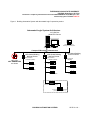
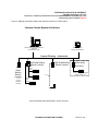
For coordination between Specification sections, Figure 1 and Figure 2 should be included at the
end of EACH Specification section that includes interfacing to the existing campus BACnet BAS at
PSU University Park (i.e. Chillers, RTU’s, VFD’s, Lighting Control, or Electrical Monitoring).
C.
rd
3 -Party Interfacing is required on this project according to the following Specification
sections for sub-systems. Figure 1 (ALC) or Figure 2 (JCI), depending on which is the
BUILDING AUTOMATION SYSTEMS
25 55 00 - 5
THE PENNSYLVANIA STATE UNIVERSITY
PSU BAS Guide Spec, 25 55 00
Document in Temporary Internet Files\Low\Content.IE5\IJKMH6IE\25 00 00 BAS Spec - Rev
Instructions[1].docx Printed: 03/07/11
selected BAS, shall be provided to the Vendor that provides the following Equipment on
this Project, so Vendor understands how the communications-networking needs to function.
2. Section 23 xx xx – Roof Top Unit(s)
3. Section 23 xx xx – Chiller(s)
4. Section xx xx xx – Variable Frequency Drive(s)
5. Section 26 xx xx – Lighting Controls
6. Section 26 xx xx – Electrical Monitoring
7. Section xxxxx - OTHER
1.4
REFERENCES
A.
1.5
ANSI/ASHRAE 135-2008: BACnet - A Data Communication Protocol for Building
Automation Systems: This shall include the Standard and all published Addenda. Refer to
www.bacnet.org for published Addenda.
DEFINITIONS
A.
BAS refers to the Building Automation System. (In the past, this may have been referred to
as CCS, Central Control System, EMS, Energy Management System, or ATC, Automatic
Temperature Control.)
B.
Critical Space refers to a space that is being backed-up by redundant utilities and/or
redundant HVAC system(s) (i.e. Animal Rooms, Temperature-critical research, etc.).
C.
CSC refers to the Control System Contractor. The CSC is the Contractor responsible for
the implementation of this Section of the Specifications.
D.
Enhanced Zone Sensor refers to a Room Sensor with Set-point Adjustment and
Occupancy Override.
E.
Gateway refers to the interface (hardware and/or software) to provide seamless integration
by non-BAS equipment manufacturers. Refer to paragraph 2A.2 “BAS Interfacing with 3rdParty Sub-systems”.
F.
I/O refers to Input/Output. Thus, "I/O device" means "Input/Output device".
G.
IP refers to the Internet Protocol.
H.
Night Lighting refers to non-emergency exterior lights mounted to the building.
I.
OEM stands for Original Equipment Manufacturer, and refers to the manufacturer of the
equipment being provided that includes a microprocessor based building sub-system
[RTU(s), Chiller(s), VFD(s), Lighting Controls, and/or Electrical Monitoring] for this Project.
J.
Object Table(s) refer(s) to the detailed listing(s) of BACnet objects and the functional
requirements using the various operator interfaces for the system. In the past, this/these
may have been referred to as "Points List(s)" and "I/O Summary".
K.
On-line refers to accessibility via the thin-client user interface.
L.
Primary Equipment refers to Heating, Cooling and/or Air Moving SOURCE equipment.
This includes HW System (pumps, HX, valves, sensors, etc.), CHW System (pumps,
Chiller, Tower, valves, sensors, etc.), ACFs, RTUs, HRUs, etc. This does NOT include
Terminal Equipment (see separate definition).
BUILDING AUTOMATION SYSTEMS
25 55 00 - 6
THE PENNSYLVANIA STATE UNIVERSITY
PSU BAS Guide Spec, 25 55 00
Document in Temporary Internet Files\Low\Content.IE5\IJKMH6IE\25 00 00 BAS Spec - Rev
Instructions[1].docx Printed: 03/07/11
1.6
M.
Terminal Equipment refers to Heating, Cooling and/or Air Moving equipment connected to
Primary Equipment and directly serving a Conditioned Zone in the Building. This includes
FCUs, CUHs, VAVs, FTR, etc. This definition is separate from Primary Equipment (see
separate definition).
N.
Thin-client User Interface refers to the software program Microsoft Internet Explorer.
O.
TNS refers to Penn State’s Telecommunications and Networking Services at The
Pennsylvania State University.
P.
OWS refers to an Operator Work Station, also seen as Operator Workstation.
Q.
“University’s Physical Plant BAS Group” refers to University employees designated by
the Office of Physical Plant (OPP) Energy & Engineering Division.
MANUFACTURER
****NOTE FOR CONSULTANT: This MAY need EDITED when using the PSU BAS GUIDE
SPEC for Projects at non-University Park campuses. Please contact the BAS Group if
there is any Question.****
A.
Automated Logic Corporation (ALC), as installed by ALC Pittsburgh branch office.
1.7
B.
Johnson Controls Inc. (JCI)
Harrisburg branch office.
(Metasys System Extended Architecture), as installed by
C.
No other Manufacturers are allowed.
SCOPE OF WORK
A.
This specification is using the DEC2010 version of the PSU BAS Guide Specification.
Some of the revisions since the JAN2008 version will affect the Scope of Work. The CSC
must carefully review this entire Specification Section 25 55 00 as the Design Professional
may also have new and added requirements.
B.
Control System Contractor's (CSC) Responsibilities:
1. The CSC shall furnish and install all necessary hardware, wiring, pneumatic tubing,
computing equipment and software required to provide a complete and functional system
necessary to perform the design intent given in the sequences of operation, and as defined
in this specification.
2. The CSC is fully responsible for coordinating the work required of the OEM when there is a
rd
3 -party sub-system provided in the project.
3. All costs associated with the work of this Section shall be included in the CSC’s contract.
4. The CSC shall coordinate the CSC’s work with other trades.
C.
System Requirements
1.
All material and equipment used shall be standard components, regularly
manufactured and available, and not custom designed especially for this project. All
systems and components, except site specific software, shall have previously been
thoroughly tested and proven in actual use prior to installation on this project.
2.
The system architecture shall be fully modular permitting expansion of application
software, system peripherals, and field hardware.
BUILDING AUTOMATION SYSTEMS
25 55 00 - 7
THE PENNSYLVANIA STATE UNIVERSITY
PSU BAS Guide Spec, 25 55 00
Document in Temporary Internet Files\Low\Content.IE5\IJKMH6IE\25 00 00 BAS Spec - Rev
Instructions[1].docx Printed: 03/07/11
3.
D.
The system, upon completion of the installation and prior to acceptance of the
project, shall perform all operating functions as detailed in this specification.
Equipment
1.
System Hardware
a.
The CSC shall provide the following:
(1)
Operator workstation(s) and control modules.
(2)
All relays, switches, sensing devices, indicating devices, and
transducers required to perform the functions listed in Object Table(s).
(3)
All monitoring and control wiring and air tubing.
**** PROJECT NOTE, for the Consultant ****
For this project, include the following item (begins with “For this project”).
This may not be a project requirement on “small” projects. Please contact
the BAS Group if there is any Question.
For coordination between Specification sections, Figure 1 and Figure 2
should be included at the end of EACH Specification section that includes
interfacing to the existing campus BACnet BAS at PSU University Park (i.e.
Chillers, RTU’s, VFD’s, Lighting Control, or Electrical Monitoring).
(4)
REVIEWER NOTE
2A.2 D. 1. A. (4)
Verify that the
Equipment Spec Sections
also have clear
language that matches.
For this project, the CSC shall connect to (physical wiring and/or via
programming) the integration gateway module(s) and software provided
by the OEM, to interface with the following third party equipment:
[possibly RTU(s), Chiller(s), VFD(s), Lighting Controls, and/or
Electrical Monitoring]
(a) Equipment type-1
(b) Equipment type-2
(c) Equipment type-3
2.
System Software
a.
The CSC shall provide all software identified in this specification. The
database required for implementation of these specifications shall be
provided by the CSC, including point descriptor, alarm limits, calibration
variables, on-line graphics, reports and point summaries. The CSC shall
provide and create the system using the latest software release, at the time
of Shop Drawing approval.
**** PROJECT NOTE, for the Consultant ****
For this project, include the following item (begins with “For this project”).
This may not be a project requirement on “small” projects. Please contact
the BAS Group if there is any Question.
BUILDING AUTOMATION SYSTEMS
25 55 00 - 8
THE PENNSYLVANIA STATE UNIVERSITY
PSU BAS Guide Spec, 25 55 00
Document in Temporary Internet Files\Low\Content.IE5\IJKMH6IE\25 00 00 BAS Spec - Rev
Instructions[1].docx Printed: 03/07/11
b.
E.
F.
Object Table(s)
1.
The system as specified shall monitor, control, and calculate all of the
points/objects and perform all the functions as listed in sequences of operation and
as shown in control diagrams in this specification.
2.
All objects, including Application Controller level objects, shall be exposed as
BACnet Objects.
Codes and Regulations
1.
2.
G.
Site-license: For this project, at least one (1) additional software license for
the existing campus Automated Logic WebCTRL or JCI Metasys System
Extended Architecture software shall be provided.
All electrical equipment and material and its installation (including programming)
shall conform to the current requirements of the following authorities:
a.
Occupational Safety and Health Act (OSHA)
b.
National Electric Code (NEC), 2008
c.
International Fire Code, 2009
d.
International Mechanical Code, 2009
e.
International Energy Conservation Code, 2009
f.
International Fuel Gas Code, 2009
g.
International Building Code, 2009
h.
International Existing Building Code, 2009
i.
International Plumbing Code, 2009
All distributed, application controllers supplied shall be in compliance with the
following listings and standards:
a.
UL916 for Open Energy Management
b.
CE Electro Magnetic Compatibility
3.
The control system manufacturer shall have quality control procedures for design
and manufacture of environmental control systems for precise control and comfort,
indoor air quality, HVAC plant operation, energy savings and preventative
maintenance.
4.
Where two or more codes conflict, the most restrictive shall apply. Nothing in this
specification or related documentation shall be construed to permit work not
conforming to applicable codes.
Building Ethernet Connection Cabling: The building Ethernet shall be provided by the
University (cooperation between Physical Plant and TNS), at the Building
Telecommunications closet(s), and a Network Switch is provided and installed by
Physical Plant personnel at this location. The CSC shall provide CAT-5e or CAT-6
cabling between Global Building Controller(s)/Router(s) and the Building
Telecommunications Closet(s). The CSC shall provide repeaters between Global
Building Controllers /Routers and the Building Ethernet Connection as required. Final
BUILDING AUTOMATION SYSTEMS
25 55 00 - 9
THE PENNSYLVANIA STATE UNIVERSITY
PSU BAS Guide Spec, 25 55 00
Document in Temporary Internet Files\Low\Content.IE5\IJKMH6IE\25 00 00 BAS Spec - Rev
Instructions[1].docx Printed: 03/07/11
Building Ethernet Connection terminations shall be by the CSC and shall be coordinated
with the University’s Physical Plant BAS Group.
1.8
H.
Major Systems Cabling: The CSC shall provide CAT-5e or CAT-6 cabling between the
Global Building Controller location and each location of an Air Handler, Heating System,
and/or Chilled Water System Panel. All terminations shall be completed by the CSC.
I.
The CSC shall provide all object mapping and programming and shall coordinate object
naming conventions and network map requirements with the University’s Physical Plant
BAS Group. The naming convention shall be submitted with the BAS Shop Drawings for
review and approval by the University’s Physical Plant BAS Group.
J.
The CSC shall provide a circuit from an existing Normal/Emergency power panel and an
UPS for the Global Building Controller/Routers and, if necessary, for repeaters and
Application Controllers serving emergency and/or critical equipment.
K.
The CSC shall provide router and software to route BACnet messages over the existing
Campus Ethernet infrastructure using BACnet standard Annex J routing (BACnet over IP).
Existing Campus Ethernet infrastructure has multiple subnets and is capable of routing IP
messages.
L.
Refer to Figure 1 and Figure 2 at the end of this Section for a graphical indication of the
Scope of Work, as it relates to the campus infrastructure and OEM equipment.
SUBMITTALS
A.
Submit under provisions of Division 1.
B.
BAS Intent Meetings:
1.
Purpose of BAS Intent Meetings: The GOAL of these Meetings is to be proactive
about having the Controls Design, including the Programming Logic, to be
consistent with the INTENT of the Systems (a “system” involves Equipment and
Sequence of Operation). The Design Intent is best understood by the Design
Engineer, and the PSU Engineering Services Engineer responsible for Reviewing
and guiding the Project. Text language can often be interpreted in different ways.
By having face-to-face discussions, mis-interpretations should be able to be
avoided early in the Construction-process.
2.
Format of Meetings:
a.
There shall be at least two (2) Meetings, but not less than the number of
Meetings that are required to adequately cover the BAS Intent. This will
depend on the size of this Project.
b.
Meeting Details:
(1)
The first BAS Intent Meeting shall be conducted by the Owner, and
shall be held prior to the CSC starting the BAS Shop Drawings
Submittal. Contact the PSU Project Manager with at least 10-days
advance notice for scheduling this Meeting.
(2)
The second (and additional) BAS Intent Meeting(s) shall be conducted
by the CSC, when the BAS Shop Drawings Submittal is approximately
50% completed, to verify that everything is “on-track” according to the
BAS Intent (defined by Designer & Owner).
BUILDING AUTOMATION SYSTEMS
25 55 00 - 10
THE PENNSYLVANIA STATE UNIVERSITY
PSU BAS Guide Spec, 25 55 00
Document in Temporary Internet Files\Low\Content.IE5\IJKMH6IE\25 00 00 BAS Spec - Rev
Instructions[1].docx Printed: 03/07/11
3.
Meeting Attendance:
a.
b.
4.
Required:
(1)
The Project’s Mechanical Design Engineer (the person responsible for,
and knowledgeable-about, the Sequences of Operation)
(2)
PSU Engineering Services Engineer (at least Mechanical, and possibly
also Electrical)
(3)
PSU BAS Group representative
(4)
Applications Engineer for the CSC (Control System Contractor)
(5)
Project Manager for the CSC
Possible:
(1)
the Project’s CM (Construction Manager) representative
(2)
Programmer /Logic-developer for the CSC
(3)
the Project’s Cx-provider
(4)
PSU Cx Services representative
(5)
PSU Project Management representative
BAS Shop Drawings Submittal, presented at the 50% completed stage, shall
include at a minimum:
a.
Cover Sheet /Title Sheet, Index, Legend and Letter of Factory Training
Credits.
b.
Communications Riser (complete for the entire Project), and Device
Addressing Scheme
c.
System Schematic, 1 for each System
d.
Sequence of Operation, 1 for each System
e.
Valve and Damper Schedules
f.
Product Data Sheets: This shall include at least a LIST of the Controllers
and Devices to be used. The “list” could be a “combined BOM”, and then
submit Product Data Sheets for just the new or not-common Devices. (The
BAS Shop Drawings Submittal (for Approval) will still include Product Data
Sheets for ALL the Materials on the Project, as these are important for future
reference)
C.
As soon as Submittals are prepared, an electronic version shall be provided simultaneously
with the mailing of the paper copies to the Project Contractor-chain.. The electronic version
shall be transmitted via e-mail, to expedite the approval process. Provide Submittal in
electronic format to:
Bob Mulhollem, Manager of Environmental Systems,
[email protected], 863-7220.
D.
Air Flow Monitoring Station (AFMS) Product Data Sheets
1.
Submit product data sheets and technical Installation, Operation and Maintenance
Manual for thermal dispersion airflow measuring devices indicating minimum
BUILDING AUTOMATION SYSTEMS
25 55 00 - 11
THE PENNSYLVANIA STATE UNIVERSITY
PSU BAS Guide Spec, 25 55 00
Document in Temporary Internet Files\Low\Content.IE5\IJKMH6IE\25 00 00 BAS Spec - Rev
Instructions[1].docx Printed: 03/07/11
placement requirements, sensor density, sensor distribution, and installed accuracy
to the host control system.
E.
BAS Shop Drawings: The Building Number and PSU Project Reference Number shall be
part of each piece of the Shop Drawings Submittal. All controls drawings shall be B-size
(11” x 17” sheet), C-size (24" x 18" sheet ) or D-size (36" x 24" sheet), and shall be
completed and provided using Visio, or AutoCAD. A minimum of four (4) copies of shop
drawings shall be submitted and shall consist of the following:
1.
Shop Drawings shall include:
a.
Cover Sheet /Title Sheet: Attached to the Front of all Submittal Sheets, this
shall include a minimum of: Project Name; Project Location; Project
Number, Building Number; CSC Contractor Name, Address, Phone
Number(s); Project Engineer Name; Mechanical Contractor Name;
Submission Date; Date and Name of the Project Construction Documents
used to create the Submittal. When resubmitted for Record Documentation,
the Date of As-Builts shall be added.
b.
Index: The first sheet of the Shop Drawings shall be an Index of all sheets in
the set.
c.
Legend: A description of symbols and acronyms used shall be provided at
the beginning of the set of Shop Drawings.
d.
Letter of Factory Training Credits, per requirements in Part 3 – Training.
e.
Communications Riser: A single-page diagram depicting the system
architecture complete with a communications riser. Riser shall include room
locations and addressing for each controller. Include a Bill of Material for all
equipment in this diagram but not included with the unique controlled
systems. Renovations and/or expansions to an existing BAS shall be
developed using the existing communications riser diagram available from
the University’s Physical Plant BAS Group.
f.
Device Addressing Scheme: Install controllers implementing an addressing
scheme consistent with the Reference-document "Device Instance at Penn
State". The document "Device Instance at Penn State.doc" is available on
the PSU Design Standards website. The addressing scheme shall be
submitted, reviewed and approved by the University’s Physical Plant BAS
Group prior to implementation.
g.
Equipment Numbering: Acronyms used for equipment installed for this
project shall follow the “Equipment Identifier Prefix Acronym” listing prepared
by the University’s Office of Physical Plant and available on the PSU Design
Standards website. The numbering assigned to equipment installed for this
project shall sequentially follow the numbering of existing equipment of the
same type in the same building. The equipment numbering scheme shall be
submitted, reviewed and approved by the University’s Physical Plant BAS
Group prior to implementation.
h.
Systems Summary: Drawings shall include a table listing each piece of
equipment and the area(s) served by each piece of equipment.
BUILDING AUTOMATION SYSTEMS
25 55 00 - 12
THE PENNSYLVANIA STATE UNIVERSITY
PSU BAS Guide Spec, 25 55 00
Document in Temporary Internet Files\Low\Content.IE5\IJKMH6IE\25 00 00 BAS Spec - Rev
Instructions[1].docx Printed: 03/07/11
i.
Valve Schedule: The Valve Schedule(s) shall be submitted using the
Template provided by PSU, and shall be reviewed and approved by the
Professional prior to installation of any Valve. The document "Valve
Schedule_Template.xls" is available on the PSU Design Standards website.
j.
Damper Schedule: The Damper Schedule(s) shall be reviewed and
approved by the Professional prior to installation of any Damper.
k.
Object Table: Object Table shall include all I/O points, all Alarm points and
all Trend points. Information on each point shall include the following:
(1)
Point type
(2)
Point description
(3)
Point name
(4)
Alarm limits, if applicable
(5)
Whether or not a Trend is Enabled on point
(6)
What Trend is triggered on, if applicable
(7)
Whether or not Trend historian (archive) is enabled on point
(8)
Event Category and Event Template assigned to point
l.
Floor Plans: Drawings shall include the proposed location of all field devices
and the routing of the communications cabling.
m.
System Schematic: Drawings shall include a single-line representation of the
equipment being controlled, including all field devices required for properly
controlling equipment and implementing the sequences of operation for this
project.
n.
Sequence of Operation: Drawings shall include Sequences of Operation for
each piece of equipment with a unique configuration. The sequences shall
be written in English text in such a way as to clearly convey how the design
sequence of operation has been implemented by the controls design
included in this Submittal. The design sequence of operation is that which is
provided in the specification for this project as provided by the Professional.
A simple duplication of the design sequence of operation provided in the
specification for this project is not acceptable. The Sequences of Operation
shall follow the outline below for a pattern of form and content. Each device
that is referred to shall have the Device Tag identified in parentheses.
(1)
TITLE
(2)
GENERAL (include Set Points, Schedule, etc.)
(3)
MODES OF OPERATION
(a)
(b)
Unoccupied
(1)
Heating
(2)
Cooling
Occupied
BUILDING AUTOMATION SYSTEMS
25 55 00 - 13
THE PENNSYLVANIA STATE UNIVERSITY
PSU BAS Guide Spec, 25 55 00
Document in Temporary Internet Files\Low\Content.IE5\IJKMH6IE\25 00 00 BAS Spec - Rev
Instructions[1].docx Printed: 03/07/11
(1)
Heating
(2)
Cooling
(3)
INTERLOCKS (i.e. Fume Hoods, Exhaust Fans, etc.)
(4)
SAFETIES (i.e. Freeze Protection, Smoke Detector, etc.)
o.
Point-to-point Wiring Details: Drawings shall include point-to-point wiring
details and must show all field devices, start-stop arrangement for each
piece of equipment, equipment interlocks, controllers, panel devices, wiring
terminal numbers and any special information (i.e. shielding requirements)
for properly controlling equipment and implementing the required sequences
of operation.
p.
Bill of Material: Drawings shall include a bill of the material necessary and
used for properly controlling equipment and implementing the required
sequences of operation. As-built documents shall include the Valves and
Dampers installed.
q.
Configuration Details: Drawings shall include programming and parameter
setup information necessary for each controller used to properly control
equipment and implement the required sequence of operation.
r.
On-line Graphics: Submit a sample of a typical graphical representation of
the equipment, logic and communication riser. The sample can be from a
previous project that had the same equipment.
s.
Each unique controlled system or piece of equipment shall include the
following items (described above):
t.
(1)
System Schematic
(2)
Sequence of Operation
(3)
Point-to-point Wiring Details
(4)
Bill of Material
(5)
Configuration Details
(6)
On-line Graphic (sample)
Controller Table: A complete table for each and every controller installed per
this project, shall be included in the BAS Shop Drawings Submittal, and a
separate electronic copy of the table in “Microsoft Excel” format, shall be
provided (via email, to Bob Mulhollem). Contact the University’s Physical
Plant BAS Group for an example or template. This table shall include the
following:
(1) The University Campus location where the equipment and controller will
be installed
(2) The official University building inventory number where the equipment
and controller will be installed
(3) The building name where the equipment and controller will be installed
(4) The BACnet device instance of the controller.
(5) The BACnet network instance that the controller shall reside on.
BUILDING AUTOMATION SYSTEMS
25 55 00 - 14
THE PENNSYLVANIA STATE UNIVERSITY
PSU BAS Guide Spec, 25 55 00
Document in Temporary Internet Files\Low\Content.IE5\IJKMH6IE\25 00 00 BAS Spec - Rev
Instructions[1].docx Printed: 03/07/11
(6) The UDP port that is being utilized by any device on the BACnet/IP
network
(7) The manufacturer’s name of the controller
(8) The manufacturer’s model number of the controller
(9) The network media type that the controller resides on
F.
2.
BAS shop drawings shall be submitted to and approved by the University’s Physical
Plant BAS Group before any aspect of the BAS installation shall proceed.
Therefore, shop drawings must be submitted in time for the Professional and the
University’s Physical Plant BAS Group review so that all installations can be
completed per the project's completion schedule. Ten working days shall be
allowed for the Professional and the University’s Physical Plant BAS Group to
review submittals.
3.
As-Built Drawings shall be created after the final system checkout, by modifying
and adding to the Shop Drawings. As-Built Drawings shall show exact installation.
As-Built Drawings will be acknowledged in writing by the Professional and the
University’s Physical Plant BAS Group after the final checkout of the system. The
system will not be considered complete until the As-Built Drawings have received
their final approval. The CSC shall deliver four sets of As-Built Drawings to the
University’s Physical Plant BAS Group, with copy of the transmittal to the
University’s Project Management. Equipment Panel As-Built Drawings shall be
provided prior to acceptance of the completed BAS installation.
4.
In addition to the Controller Table listed above, and before final configuration, the
CSC shall provide Object Table(s) form(s) to the Professional and the University’s
Physical Plant BAS Group that include:
a.
Description of all points/objects.
b.
Listing of binary and analog hardware required to interface to the equipment
for each function.
c.
Listing of all application programs associated with each piece of equipment.
d.
BACnet device and object instances.
e.
Event Parameters.
f.
Failure modes for control functions to be performed in case of failure.
Construction Schedule of CSC’s milestones:
1.
The CSC shall submit to the University’s Project Management a detailed schedule,
identifying all activities from the contract award to system warranty expiration. The
schedule shall be coordinated with all other Contractors and shall be submitted
within 90 days after the notice to proceed. The schedule shall include, but shall not
be limited to, the following milestones:
a.
notice to proceed;
b.
submittal of this detailed-schedule
c.
date for the first BAS Intent Meeting, to be scheduled (by PSU, the Owner)
prior to the CSC starting the BAS Shop Drawings Submittal (if the date for
BUILDING AUTOMATION SYSTEMS
25 55 00 - 15
THE PENNSYLVANIA STATE UNIVERSITY
PSU BAS Guide Spec, 25 55 00
Document in Temporary Internet Files\Low\Content.IE5\IJKMH6IE\25 00 00 BAS Spec - Rev
Instructions[1].docx Printed: 03/07/11
this Meeting occurs before the detailed-schedule is submitted, then date of
notification to the PSU Project Manager should also be included) ;
d.
distribute the Preliminary BAS Shop Drawings Submittal for review and
comment by the Design Engineer and the University’s Engineering Services
Engineer;
e.
the second BAS Intent Meeting, conducted by the CSC when the BAS Shop
Drawings Submittal is approximately 50% completed (additional Meetings,
as necessary, can be included but are not required to be included);
f.
submit BAS Shop Drawings Submittal, and associated hardware and
software documentation, for review and approval by the University’s Physical
Plant BAS Group;
g.
receive work approval; Notice: No portion of the field installation may begin
without the Physical Plant BAS Group’s approval of working drawings, and
hardware, firmware and software documentation, unless specific written
instructions to the contrary are provided by the University’s Physical Plant
BAS Group.
h.
begin field installation;
i.
complete installation of all thermowells;
j.
complete installation of wiring runs;
k.
complete installation of remote field devices;
l.
deliver major BAS components and operator interface / telecommunications
equipment;
m.
complete installation of panels, communication equipment, processors, etc.;
n.
complete installation of operator interface and telecommunications
equipment;
o.
complete identification of all BAS equipment;
p.
complete initial applications engineering and provide the University’s
Physical Plant BAS Group with programming and database for review;
q.
revise programming input variables, as required;
r.
submit copy of construction mark-up set for review and use in
commissioning;
s.
commission system, using the initial set of online graphics (systems and
dynamic thermo-graphic floorplans);
t.
notify the University’s Project Management and Physical Plant BAS Group, in
writing, of system completion and preparations for acceptance testing;
u.
schedule acceptance testing to permit a member of the University’s Physical
Plant BAS Group to be present;
v.
provide assistance to Cx-provider, as-necessary per Project Scope;
w.
complete punch list items;
BUILDING AUTOMATION SYSTEMS
25 55 00 - 16
THE PENNSYLVANIA STATE UNIVERSITY
PSU BAS Guide Spec, 25 55 00
Document in Temporary Internet Files\Low\Content.IE5\IJKMH6IE\25 00 00 BAS Spec - Rev
Instructions[1].docx Printed: 03/07/11
G.
x.
complete training, using construction mark-up set of BAS Shop Drawings;
y.
submit approved as-built drawings, and complete revisions to the initial set of
online graphics;
z.
initiate warranty period;
aa.
terminate warranty period.
2.
The CSC shall submit similarly detailed schedule information, revised if necessary,
for any additional work which will extend the effectiveness of the BAS and is
contracted either concurrent to or immediately following the term of the present
installation. It shall be the responsibility of the CSC to alert the University’s Project
Management of any scheduling conflicts, and to defer to the judgment of the
University in the resolution of those conflicts.
3.
The CSC shall provide additional workers and/or overtime hours as deemed
necessary by the University to meet scheduled completion dates.
4.
Should the CSC fail to maintain any part of the installation schedule, the University
reserves the right to require written weekly progress reports. If the University so
elects, the CSC shall provide a then-current schedule and shall provide written
updates to that schedule to both the University and the Professional on a weekly
basis. If this option is exercised by the University, the schedule shall be delivered
to the University and the Professional no later than the Thursday immediately
preceding the week during which the schedule will become effective. Bidders will
note that it remains the intent of the University to execute all available remedies
under this contract to ensure the CSC’s best efforts to satisfy the initial milestone
scheduling. All programming tools shall be provided as part of the system. CSC
shall provide any system upgrades released during the warranty period free of
charge to the University.
Operating and Maintenance Manuals
1.
Operating and Maintenance (O&M) manuals for the system shall include the
following categories: Workstation User's Manual and Project Engineering
Handbook, and Software Documentation. Project specific manuals shall include
detailed information describing the specific installation.
a.
b.
Workstation User's Manual shall contain as a minimum:
(1)
System overview.
(2)
Networking architecture.
(3)
The object tables.
(4)
The sequences of operation.
(5)
The graphical programming.
(6)
Established setpoints and schedules.
(7)
Summary of trend objects.
(8)
User manuals for the ‘third party’ software
Project Engineering Manual shall contain as a minimum:
BUILDING AUTOMATION SYSTEMS
25 55 00 - 17
THE PENNSYLVANIA STATE UNIVERSITY
PSU BAS Guide Spec, 25 55 00
Document in Temporary Internet Files\Low\Content.IE5\IJKMH6IE\25 00 00 BAS Spec - Rev
Instructions[1].docx Printed: 03/07/11
(1)
System architecture overview
(2)
Hardware cut-sheets and product descriptions
(3)
Wiring diagrams for all controllers and field hardware
(4)
Installation, mounting and connection details for all field hardware and
accessories
(5)
Commissioning and setup parameters for all field hardware
(6)
Maintenance procedures, including final tuning and calibration
parameters.
(7)
Spare parts list.
(8)
Record Software Documentation shall contain as a minimum:
(a)
H.
I.
1.9
Graphical programming must be represented using either Visio
or AutoCAD.
(b) Graphical representation of all control logic for every piece of
mechanical equipment controlled on the project, together with a
glossary or icon symbol library detailing the function of each
graphical icon. 'Line by line' computer program documentation is
unacceptable.
(c)
Detailed description of control sequences used to achieve the
specified sequences.
PICS: Provide a BACnet Protocol Implementation Conformance Statement (PICS) for each
system element proposed (Operator workstation, LAN Gateway/Controller, Logic
Controller, Routers, Repeaters, Converters, Application Controllers). This PICS shall
contain all of the information described in Section 22.1.1.1, and shall be in the format found
in Annex A, of ASHRAE Standard 135.
Provide complete description and documentation of any proprietary services and/or objects.
COORDINATION WITH OTHER CONTRACTORS
**** PROJECT NOTE, for the Consultant ****
Paragraph “A” below is required if the Project is NOT New Construction. If there is no
existing building, this does not need to be included. Please contact the BAS Group if
there is any Question.
Coordinate with Part 3 WIRING DEMOLITION
A.
When the Project involves removal and/or demolition of existing BAS Panel(s) and/or BAS
cables (wire or fiber):
1.
Contact the Project Manager and BAS Group to coordinate the disconnection of
the equipment from the active CCS network, and
2.
All wiring and tubing abandoned by the work of the CSC, during the course of
completing this Project, shall be removed in total. Abandoned Controllers, Panels
and Devices shall be retained by, and as determined by, PSU Physical Plant Area
Services.
BUILDING AUTOMATION SYSTEMS
25 55 00 - 18
THE PENNSYLVANIA STATE UNIVERSITY
PSU BAS Guide Spec, 25 55 00
Document in Temporary Internet Files\Low\Content.IE5\IJKMH6IE\25 00 00 BAS Spec - Rev
Instructions[1].docx Printed: 03/07/11
3.
Contact the Project Manager and the Area Services Supervisor to coordinate the
placement of removed equipment into an inventory of Spare Parts for the Building
being renovated or demolished.
B.
Review the installation of all controlled systems such as air handling equipment, duct work,
piping, pumps, chillers, fans, and similar equipment for the purpose of providing the
appropriate installing contractor correct information for wells, relays, panels, access panels,
and similar appurtenances required for the control system. Such information shall include
physical size, proper location and orientation, and accessibility requirements.
C.
The CSC shall coordinate the installation of all control devices, and shall ensure that
supporting work by others such as installation of thermometer wells, pressure taps, orifice
plates and flanges, access panels, electronic transducers, and other items required are
included. The CSC shall schedule and coordinate the work to ensure that the items are
installed in the proper manner at the appropriate time.
**** PROJECT NOTE, for the Consultant ****
Design Professional needs to make sure the Mechanical Section 23 05 19 includes
Pressure and Temperature test plugs (P/T ports) that are required adjacent to all
electronic pressure and temperature BAS sensors in hydronic systems (for
testing/calibration purposes).
D.
1.10
Coordinate the Pressure and Temperature test plugs (P/T ports) that are required adjacent
to all electronic pressure and temperature BAS sensors in hydronic systems (for
testing/calibration purposes). Installed per Section 23 05 19.
CONTRACTOR (CSC) EXPERIENCE AND PERFORMANCE
A.
The University requires a BAS that is installed, programmed, commissioned, and serviced
by an experienced CSC. To insure the University of proper BAS service and support, the
CSC shall be the authorized distributor of the BAS manufacturer for the local area and if
requested by the University shall supply proof thereof. In view of this, the CSC shall have
installed a minimum of five BASs of the same type and size as the BAS herein specified
and shall provide job names, a brief description of the scope of each BAS job, and a point
of contact for each job. The actual, local CSC or BAS branch office, rather than the BAS
manufacturer, will provide this information.
B.
The CSC shall have a local office or representative within the state of Pennsylvania, staffed
with factory trained engineers, fully capable of providing instruction, routine maintenance,
and emergency maintenance service on all system components. The CSC shall be
responsible for replacement of: the controllers with current job software, printer, PC(s),
sensors, and devices at all times for a period of not less than 1 year following project
completion, and shall guarantee replacement and software reprogramming of a system in
need of repair, within a 24 hour period after notification from the University. In the case of
an after-hours emergency, the CSC shall provide after-hours emergency services which
will, upon notification of an emergency situation, result in CSC personnel being on-site
within four hours if necessary.
C.
The CSC must have an acceptable performance record with the University. The
performance record of the CSC will be subject to an annual review by the University’s
Physical Plant BAS Group.
BUILDING AUTOMATION SYSTEMS
25 55 00 - 19
THE PENNSYLVANIA STATE UNIVERSITY
PSU BAS Guide Spec, 25 55 00
Document in Temporary Internet Files\Low\Content.IE5\IJKMH6IE\25 00 00 BAS Spec - Rev
Instructions[1].docx Printed: 03/07/11
1.11
WARRANTY & SERVICE
A.
Provide warranty under provisions of Division 1.
B.
Provide all services, materials and equipment necessary for the successful operation of this
system for a period of one year. Provide all recommended preventive maintenance which is
indicated in the O&M Manuals during this period. In addition, provide two (2) semi-annual
visits for testing and evaluating the performance of the networked equipment installed per
this specification. One visit shall be during the cooling season and one visit shall be during
the heating season. Provide a written report after each visit is complete. Coordinate
service visits through the University’s Physical Plant BAS Group. This service visit shall
include, but not be limited to, the following:
C.
D.
1.
Check calibration and re-calibrate if needed instrumentation sensors for air flow,
liquid flow, pressure, humidity, temperature, and transducers. Written records shall
be kept indicating the performance of such calibrations along with pertinent data.
2.
Check the operation of dampers and damper actuators to assure no lock up has
occurred and stroke is proper. Written records shall be kept indicating the
performance of such calibrations along with pertinent data.
3.
Check the overall system field operations by performing an all-points review (by
hard copy or by documenting all-point inquiries). Verify that all monitoring and
command points are valid and active.
4.
Written records shall be kept indicating the performance of such exercises.
If a problem develops at any time during the warranty/service period, the CSC shall monitor
and log the affected BAS point/object for the remainder of the warranty/service period. “A
problem” in the above statement will refer to an incident in which any of the following occur:
1.
An alarm occurs due to defective control system components or improper
installation or programming.
2.
Overall performance of the system is compromised due to defective control
components or improper installation or programming.
3.
Major recalibration (by greater than 5 times the catalogued accuracy) is required for
a sensor during one of the service visits.
The CSC shall provide any system software upgrades released during the warranty period,
free of charge to the University.
---- End of PART 1 --------------------------
BUILDING AUTOMATION SYSTEMS
25 55 00 - 20
THE PENNSYLVANIA STATE UNIVERSITY
PSU BAS Guide Spec, 25 55 00
Document in Temporary Internet Files\Low\Content.IE5\IJKMH6IE\25 00 00 BAS Spec - Rev
Instructions[1].docx Printed: 03/07/11
PART 2A
2A.1
PRODUCTS, HARDWARE
NETWORKING/COMMUNICATIONS
A.
The design of the hardware and software shall network existing operator workstations at
the PSU Campus with new Global Building Controllers /Routers provided under this
Section. The network shall be implemented via the Campus shared Ethernet system. The
campus shared Ethernet backbone uses IP communication protocol.
**** PROJECT NOTE, for the Consultant ****
For this project, include the following item (begins with “For this project”). This
may not be a project requirement on “small” projects. Please contact the BAS
Group if there is any Question.
1.
2A.2
Ethernet Switch: For this project, the CSC shall provide an Ethernet switch in the
same panel with the Global Building Controller /Router, to connect the Global
Building Controller to the campus shared Ethernet backbone. This hardware shall
be a 5-port 10/100 Mbps Ethernet-switch with DIN-rail mount; Contemporary
Controls Model EISK5-100T or Equivalent.
B.
All network parameters must be assigned and approved by the University’s Physical Plant
BAS Group prior to implementation.
C.
The system must be fully BACnet compliant at the time of installation. This means that
the system must use BACnet as the native communication protocol between workstations
or servers on the network.
D.
The BACnet communication protocol is the required protocol for all tiers of the network.
RD
BAS INTERFACING WITH 3 -PARTY SUB-SYSTEMS
A.
General: The CSC shall be responsible for connecting all sub-systems to the BAS via
native BACnet, or if not native BACnet, a sub-system shall be integrated via a gateway that
converts the proprietary protocol to the BACnet protocol. Sub-systems include RTU(s),
VFD(s), Chiller(s), Lighting Controls and/or Electrical Monitoring provided as part of this
project (refer to Figure 1 and Figure 2 at the end of this specification section and related
specification sections). These sub-systems shall be controlled, monitored and graphically
programmed through the Graphical User Interface (GUI) software of the BAS.
****NOTE FOR CONSULTANT: Coordination of these requirements is required in any
Section specifying OEM electrical/mechanical sub-systems with interoperability integrated
into the BAS.****
B.
Gateway: The gateway(s), required for the sub-system(s), shall be provided by the OEM.
The gateway(s) is(are) further specified below:
1.
The gateway Submittal shall be provided by the OEM to the CSC to be included
with the BAS Shop Drawings Submittal, for review and approval by the University’s
Physical Plant BAS Group.
BUILDING AUTOMATION SYSTEMS
25 55 00 - 21
THE PENNSYLVANIA STATE UNIVERSITY
PSU BAS Guide Spec, 25 55 00
Document in Temporary Internet Files\Low\Content.IE5\IJKMH6IE\25 00 00 BAS Spec - Rev
Instructions[1].docx Printed: 03/07/11
2.
All system information specified in the sequence of operation and related
documents shall be available to the BAS. Read and write capability, as indicated
by an object table provided by the OEM, shall be provided to the mechanical and
electrical equipment indicated and be available to the BAS system. The OEM shall
provide to the CSC, a table of gateway objects and their functionality, including
normal operating limits (i.e. High and Low Oil Temperature Limits from a Chiller
control panel).
3.
Define how the gateway interaction with equipment will comply with this section.
OEMs shall bid a fully BACnet compliant device to facilitate interoperability between
OEM electrical/mechanical sub-systems and the BACnet BAS or provide the
necessary gateway to integrate into the web-based BACnet BAS (WebCTRL, or JCI
Metasys System Extended Architecture) using the BACnet protocol.
4.
C.
a.
The OEM shall provide any software or hardware required to access or
modify any electrical/mechanical subsystems (i.e. RTUs, VFD, Chillers,
Lighting Controls and/or Electrical Monitoring).
b.
Typical gateway requirements for projects include: A BACnet interface to the
chiller manufacturer’s product(s), a BACnet interface to the lighting controls
manufacturer’s product(s), a BACnet interface to the VFD manufacturer’s
product(s), a BACnet interface to the electrical monitoring manufacturer’s
product(s) (Square D or Cutler-Hammer), a BACnet interface to the lab
equipment manufacturer’s product(s). A Modbus interface may be used only
when a BACnet interface is not available.
If the equipment manufacturer does not have this capability, they shall contact the
authorized representative of the CSC for assistance and shall include in their
equipment price any necessary hardware and/or software obtained from the CSC to
comply with this section.
OEM Configuration Tools and Licenses: Configuration Tools, and all software licenses,
required to configure all OEM controllers installed on this project shall be provided.
BUILDING AUTOMATION SYSTEMS
25 55 00 - 22
THE PENNSYLVANIA STATE UNIVERSITY
PSU BAS Guide Spec, 25 55 00
Document in Temporary Internet Files\Low\Content.IE5\IJKMH6IE\25 00 00 BAS Spec - Rev
Instructions[1].docx Printed: 03/07/11
2A.3
GLOBAL BUILDING CONTROLLER /ROUTER
A.
B.
C.
Acceptable Products:
1.
ALC: LGR Ethernet Router
2.
JCI: NAE (Network Automation Engine)
GENERAL - Global Building Controller /Router
1.
The Global Building Controller /Router shall be a microprocessor based
communications device. One of the functions of the Global Building Controller
/Router is to provide a communications gateway between a controller network and
an IP Ethernet network. The Global Building Controller /Router shall communicate
via IP and be connected to the PSU campus Ethernet infrastructure. A sufficient
number of controllers shall be supplied to fully meet the requirements of this
specification. Controller networks shall use the BACnet protocol.
2.
The Global Building Controller /Router shall support a network of at least 50
controllers.
3.
The Global Building Controller /Router shall provide a port which can be connected
to Operator Workstations, portable computers, or modems.
4.
Global Building Controller /Router shall provide full arbitration between multiple
users, whether they are communicating through the same or different Global
Building Controller /Routers.
5.
The Global Building Controller /Router shall be responsible for routing global
information from the various controller networks which may be installed throughout
a building.
6.
The Global Building Controller /Router shall not contain a mechanical hard-drive.
Memory: Each Global Building Controller /Router shall have sufficient memory to support
its own operating system and databases including:
1.
Control processes
2.
Energy Management Applications
3.
Alarm Management
4.
Historical/Trend Data for 100% of all physical I/O for all programs in the Global
Building Controller, at a minimum of 500 samples per Trend.
5.
Maintenance Support Applications
6.
Custom Processes
7.
Operator I/O
D.
Expandability: The system shall be modular in nature, and shall permit easy expansion
through the addition of software applications, workstation hardware, application controllers,
sensors, and actuators.
E.
Integrated On-Line Diagnostics: Each Global Building Controller /Router shall continuously
perform self-diagnostics, communication diagnosis and diagnosis of all subsidiary
BUILDING AUTOMATION SYSTEMS
25 55 00 - 23
THE PENNSYLVANIA STATE UNIVERSITY
PSU BAS Guide Spec, 25 55 00
Document in Temporary Internet Files\Low\Content.IE5\IJKMH6IE\25 00 00 BAS Spec - Rev
Instructions[1].docx Printed: 03/07/11
equipment. The Global Building Controller /Router shall provide both local and remote
annunciation of any detected component failures, or repeated failure to establish
communication. Indication of the diagnostic results shall be provided at each Global
Building Controller /Router, and shall not require the connection of an operator I/O device.
F.
Surge and Transient Protection: Isolation shall be provided at all network terminations, as
well as all field point terminations to suppress induced voltage. Isolation levels shall be
sufficiently high as to allow all signal wiring to be run in the same conduit as high voltage
wiring where acceptable by electrical code.
G.
Powerfail Restart: In the event of the loss of normal power, there shall be an orderly
shutdown of all Global Building Controllers /Routers to prevent the loss of database or
operating system software. Non-Volatile memory shall be incorporated for all critical Global
Building Controller /Router configuration data, and battery back-up shall be provided to
support the real-time clock and all volatile memory for a minimum of 72 hours.
H.
I.
2A.4
1.
Upon restoration of normal power, the Global Building Controller /Router shall
automatically resume full operation without manual intervention.
2.
Should Global Building Controller /Router memory be lost for any reason, the user
shall have the capability of reloading the Global Building Controller /Router via the
Local Area Network (LAN).
Communications:
1.
The controller network shall use BACnet as its native communication protocol.
The communication between controllers shall be ARCNET or MS/TP at least 38.4
Kbps.
2.
The Global Building Controller /Router shall utilize FLASH memory, battery backed
RAM or firmware which shall allow for operating system updates to be performed
remotely via TCP/IP or UDP/IP.
UPS: Uninterruptible Power Supply(s) is(are) required for the Global Building Controller(s),
repeater(s) and/or Application Controllers that serve or monitor emergency and/or critical
equipment.
APPLICATION CONTROLLERS
A.
B.
Acceptable Products:
1.
ALC: ME-line, SE-Line, and ZN-Line Controllers.
2.
JCI: NCE, FEC-line of Controllers (BACnet), VMA Series 1600 (BACnet).
GENERAL - Application Controllers
1.
Definition: An Application Controller, for this specification, could be an AAC
(Advanced Application Controller) or an ASC (Application Specific Controller).
These would be used on Primary Equipment and Terminal Equipment, respectively.
2.
Application controllers must use BACnet as the native communication protocol
between controllers.
3.
Each Application Controller must be capable of standalone direct digital operation
utilizing its own processor, non-volatile flash memory, input/output, minimum 8 bit A
BUILDING AUTOMATION SYSTEMS
25 55 00 - 24
THE PENNSYLVANIA STATE UNIVERSITY
PSU BAS Guide Spec, 25 55 00
Document in Temporary Internet Files\Low\Content.IE5\IJKMH6IE\25 00 00 BAS Spec - Rev
Instructions[1].docx Printed: 03/07/11
to D conversion, and include voltage transient and lightning protection devices.
Firmware revisions to the module must be able to be made from the local
workstation, portable operator terminals or from remote locations over modems or
LANs.
4.
The Application Controllers for Primary Equipment shall be expandable to the
specified I/O point requirements. Each controller shall accommodate multiple I/O
Expander Modules via a designated expansion I/O bus port. The controller, in
conjunction with the expansion modules, shall act as one application controller.
5.
All point data, algorithms and application software within the controllers shall be
custom programmable from the Operator Workstation.
6.
Each Application Controller shall execute application programs, calculations, and
commands via a microcomputer resident in the controller. All operating parameters
for application programs residing in each controller shall be stored in read/write-able
nonvolatile flash memory within the controller and will be able to upload/download
to/from the Operator Workstation.
7.
Each Application Controller shall be configured on the workstation/server software
as a BACnet device. All of the points shall be configured as BACnet objects.
Each controller shall include self-test diagnostics which allow the controller to
automatically relay to the Global Building Controller /Router any malfunctions or
alarm conditions that exceed desired parameters as determined by programming
input.
8.
Each Application Controller should be capable of performing event notification
(alarming).
9.
Each Application Controller should be capable of scheduling using an on-board
real-time clock.
10.
Each Application Controller shall contain both software and firmware to perform full
DDC PID control loops.
11.
Each Application Controller shall contain a port for the interface of maintenance
personnel's portable computer. All network interrogation shall be possible through
this port.
12.
If being installed outdoors, the Application Controllers shall be capable of being
mounted directly in or on the equipment located outdoors. The Application
Controllers shall be capable of proper operation in an ambient temperature
environment of -20 degrees F to + 150 degrees F.
13.
Input-Output Processing:
a.
Digital outputs shall be relays or triacs, 24VAC or VDC minimum. Each
output shall be configurable as normally open or normally closed.
b.
Universal inputs shall be capable of, 0-20mA, dry contact, and 0-5VDC or 010VDC.
c.
Analog output shall be electronic, voltage mode 0-10VDC or current mode 420mA.
BUILDING AUTOMATION SYSTEMS
25 55 00 - 25
THE PENNSYLVANIA STATE UNIVERSITY
PSU BAS Guide Spec, 25 55 00
Document in Temporary Internet Files\Low\Content.IE5\IJKMH6IE\25 00 00 BAS Spec - Rev
Instructions[1].docx Printed: 03/07/11
d.
Enhanced Zone Sensor Input shall provide one thermistor input, one local
setpoint adjustment, one timed local override switch, and an occupancy
indicator.
e.
Analog pneumatic outputs shall be 0-20psi. Each pneumatic output shall
have a feedback transducer to be used in the system for any software
programming needs. The feedback transducer shall measure the actual psi
output value and not a calculated value. An LED shall indicate the state of
each output.
f.
All programming sequences shall be stored in non-volatile memory. All
programming tools shall be provided as part of the system. Provide
documentation of all programming including configuration files.
14.
Each Application Controller shall execute application programs, calculations, and
commands via a microcomputer resident in the Application Controller. All operating
parameters for application programs residing in each Application Controller shall be
stored in read/write-able nonvolatile flash memory within the controller. Firmware
revisions, application programs and program modifications to the controller shall be
capable of being performed over the Wide Area Network (WAN).
15.
Application Controller output circuits shall be optically isolated.
16.
Each Application Controller shall be able to support various types of zone
temperature sensors, such as temperature sensor only, temperature sensor with
built-in local override switch, with setpoint adjustment switch.
17.
Each Application Controller for VAV application shall have a built-in air flow
transducer for accurate air flow measurement in order to provide the Pressure
Independent VAV operation.
18.
Each Application Controller for VAV applications shall have an integral direct
coupled electronic actuator. The actuator shall provide on-off/floating point control
with a minimum of 35 in-lb of torque. The assembly shall mount directly to the
damper operating shaft with a universal V-Bolt clamp assembly. The actuator shall
not require any limit switches, and shall be electronically protected against
overload. When reaching the damper or actuator end position, the actuator shall
automatically stop. The gears shall be manually disengaged with a button on the
assembly cover. The position of the actuator shall be indicated by a visual pointer.
The assembly shall have an anti-rotational strap.
19.
Each Application Controller shall have LED indication for visual status of
communication and power.
20.
Astronomical Time: Astronomic capability shall allow the system to calculate
sunrise and sunset times based on geographical location, and incorporate Daylight
Savings Time, for dusk-to-dawn control or dusk-to-time control. This is required in
any Application Controller with I/O for the Exterior lighting circuit(s).
21.
In the event of a loss of communication, the Application Controller shall control from
a standalone algorithm which maintains the assigned space temperature until
communication is restored.
22.
UPS: Uninterruptible Power Supply(s) is(are) required for any Application Controller
that monitors or serves emergency and/or critical equipment.
BUILDING AUTOMATION SYSTEMS
25 55 00 - 26
THE PENNSYLVANIA STATE UNIVERSITY
PSU BAS Guide Spec, 25 55 00
Document in Temporary Internet Files\Low\Content.IE5\IJKMH6IE\25 00 00 BAS Spec - Rev
Instructions[1].docx Printed: 03/07/11
23.
All Application Controller level objects shall be exposed as BACnet Objects.
24.
Primary Equipment shall be controlled using the same Application Controller, when
possible.
25.
Each Application Controller for Primary Equipment shall contain the following as
Spare I/O:
a.
b.
Minimum of: (3) Spare Universal Inputs (or 2-DIs and 1-AI), (1) Spare AO,
and (2) Spare DOs.
In addition to the Minimum, the Application Controller shall have 10% Spare
I/O, of each type; UI (or DI and AI), AO and DO.
**** PROJECT NOTE, for the Consultant ****
For this project, include the following item (begins with “For this project”). This will not be a
project requirement on all projects. Please contact the Project Manager or the BAS Group if there
is any Question.
2A.5
LAB CONTROLS
A.
For this project, the CSC shall provide the following equipment for Lab Controls, including
duct-mounted boxes and DDC controllers.
B.
LSB and LEB type boxes:
Duct-mounted Lab Supply Box(es) (LSBs) and Lab Exhaust Box(es) (LEBs) shall be
provided by the CSC, and shall be controlled by the appropriate control strategy, as noted
below.
****NOTE FOR CONSULTANT: Include only ONE of the following. “High-end” performance.
required when the project requirements include active-pressurization control as part of the
Mechanical Design; or “Low-tech” performance when there are Labs in the project, but they do
not require active-pressurization control as part of the Mechanical Design..
THEN, select the CORRESPONDING selection for “DDC Controllers”. ****
1.
“High-end” performance.
OR
“Low-tech” performance.
C.
DDC Controller(s)
1.
“High-end” performance. The controls with this option will be provided by the
Manufacturer of the LSB(s) and :LEB(s), and integrated into the BAS being installed
for the entire building. CSC shall provide all software configuration tools and sitelicense(s).
OR
“Low-tech” performance. The controls with this option will be provided by the BAS
being installed for the entire building.
BUILDING AUTOMATION SYSTEMS
25 55 00 - 27
THE PENNSYLVANIA STATE UNIVERSITY
PSU BAS Guide Spec, 25 55 00
Document in Temporary Internet Files\Low\Content.IE5\IJKMH6IE\25 00 00 BAS Spec - Rev
Instructions[1].docx Printed: 03/07/11
**** PROJECT NOTE, for the Consultant ****
For this project, include the following item (begins with “For this project”). This may not be a
project requirement on “small” projects. Depending on the Size of the Project the requirement is
for One or Two Laptops to be provided. Please contact the BAS Group if there is any Question.
2A.6
2A.7
LAPTOP COMPUTER(S)
A.
For this project, the CSC shall provide [one] [two] Laptop Computer(s) to the University’s
Physical Plant BAS Group prior to the start of the Acceptance Testing (reference
subsection 3.11 - ACCEPTANCE OF COMPLETED BAS INSTALLATION).
B.
Provide a new laptop computer with the control system software and database as part of
the project. Computer, in original packaging, is to be delivered to the University’s Physical
Plant BAS Group via the Project Contractor-chain and the University’s Project
Management.
C.
Provide an Allowance of $2000 per Laptop, at time of Bidding.
D.
At time of Purchase, contact PSU Physical Plant ITS group ( 865-7509 or [email protected] )
for the minimum specifications of the Laptop to be provided. Cost overruns or underruns
shall be handled via Change-Order via the Project Contractor-chain and the University’s
Project Management.
FIELD HARDWARE/INSTRUMENTATION
A.
Input Devices - General Requirements
1.
Temperature sensors shall be of the type and have accuracy ratings as indicated
and/or required for the application and shall permit accuracy rating of within 1% of
the temperature range of their intended use.
2.
Sensors used for mixed air application shall be the averaging type and have an
accuracy of ± 1 degrees F.
3.
Outside air temperature sensors shall have a minimum range of -52 degrees F to
152 degrees F and an accuracy of within ± 1 degrees F in this temperature range.
4.
Room temperature sensors shall have an accuracy, of ± 1.0 degrees F in the range
of 32 degrees F to 96 degrees F.
5.
Chilled water and condenser water sensors shall have an accuracy of ± 0.25
degrees F in their range of application.
6.
Hot water temperature sensors shall have an accuracy of ± 0.75 degrees F over the
range of their application.
7.
Temperature-differential measurement shall use a matched set of sensors.
**** PROJECT NOTE, for the Consultant ****
For this project, EDIT the following paragraphs for Sensors, Thermostats, Valve and Damper
Actuators and Control Valves. Contact the Project Manager or the BAS Group if there is any
Question.
BUILDING AUTOMATION SYSTEMS
25 55 00 - 28
THE PENNSYLVANIA STATE UNIVERSITY
PSU BAS Guide Spec, 25 55 00
Document in Temporary Internet Files\Low\Content.IE5\IJKMH6IE\25 00 00 BAS Spec - Rev
Instructions[1].docx Printed: 03/07/11
2A.8
SENSORS
A.
AIR FLOW MEASUREMENT STATIONS (AFMS-x): See separate paragraph. These are
considered more than just a “sensor”.
B.
Electronic Sensors: Vibration and corrosion resistant; for wall, immersion, or duct
mounting as required.
1.
2.
Thermistor temperature sensors as follows:
a.
Accuracy: Plus or minus 0.5 deg F (0.3 deg C) at calibration point.
b.
Wire: Twisted, shielded-pair cable.
c.
Insertion Elements in Ducts: Single point, 18 inches (20 cm)long; use where
not affected by temperature stratification or where ducts are smaller than 9
sq. ft. (1 sq. m).
d.
Averaging Elements in Ducts: 72 inches long, flexible; use where prone to
temperature stratification or where ducts are larger than 9 sq. ft. (1 sq. m);
length as required.
e.
Insertion Elements for Liquids: Brass socket with minimum insertion length
of 2-1/2 inches (64 mm).
f.
Room Sensors: With Set-point Adjustment and Occupancy Override
(Enhanced Zone Sensor), except when placed in Public Spaces. Sensors
that must be installed on exterior walls shall include insulating bases. Refer
to Part 3 for Execution requirements.
g.
Outside-Air Sensors: Watertight inlet fitting, shielded from direct sunlight.
h.
Room Temperature Security Sensors: Stainless-steel cover plate with
insulated back and security screws.
Resistance Temperature Detectors: Platinum.
a.
Accuracy: Plus or minus 0.2 percent at calibration point.
b.
Wire: Twisted, shielded-pair cable.
c.
Insertion Elements in Ducts: Single point, 18 inches (20 cm)long; use where
not affected by temperature stratification or where ducts are smaller than 9
sq. ft. (1 sq. m).
d.
Averaging Elements in Ducts: Minimum 72 inches long, flexible; use where
prone to temperature stratification or where ducts are larger than 9 sq. ft. (1
2
2
sq. m); length as required. Total length: 5 ft (1.5m) per 10 ft (1 m ) of duct
cross-section.
e.
Mixed Air Temperature (MAT) shall be an averaging-type sensor, minimum
2
20ft length. For a Coil more than 20 ft , provide 1 ft (3 m) of sensing element
2
2
for each 1 ft (1 m ) of downstream face area of the mixing plenum.
f.
Insertion Elements for Liquids: Brass socket with minimum insertion length
of 2-1/2 inches (64 mm).
BUILDING AUTOMATION SYSTEMS
25 55 00 - 29
THE PENNSYLVANIA STATE UNIVERSITY
PSU BAS Guide Spec, 25 55 00
Document in Temporary Internet Files\Low\Content.IE5\IJKMH6IE\25 00 00 BAS Spec - Rev
Instructions[1].docx Printed: 03/07/11
3.
4.
5.
C.
g.
Room Sensors: With Set-point Adjustment and Occupancy Override, except
when placed in Public Spaces. Sensors that must be installed on exterior
walls shall include insulating bases.
h.
Outside-Air Sensors: Watertight inlet fitting, shielded from direct sunlight.
i.
Room Temperature Security Sensors: Stainless-steel cover plate with
insulated back and security screws.
Humidity Sensors: Bulk polymer sensor element.
a.
Accuracy: 5 percent full range with linear output.
b.
Another standard span for room sensors below is 20 to 90 percent relative
humidity with 2 percent accuracy.
c.
Room Sensors: With cover matching room thermostats, span of 25 to 90
percent relative humidity.
d.
Duct and Outside-Air Sensors: With element guard and mounting plate,
range of 0 to 100 percent relative humidity.
Static-Pressure Transmitter: Nondirectional sensor with suitable range for expected
input, and temperature compensated.
a.
Accuracy: 2 percent of full scale with repeatability of 0.5 percent.
b.
Output: 4 to 20 mA.
c.
Building Static-Pressure Range: 0 to 0.25 inch wg (0 to 62 Pa).
d.
Duct Static-Pressure Range: 0 to 5 inches wg (0 to 1243 Pa).
Pressure Transmitters: Direct acting for gas, liquid, or steam service; range
suitable for system; proportional output 4 to 20 mA.
Equipment operation sensors as follows:
1.
Status Inputs for Fans: Differential-pressure switch with adjustable range of 0 to 5
inches wg (0 to 1243 Pa).
2.
Status Inputs for Pumps: Differential-pressure switch piped across pump with
adjustable pressure-differential range of 8 to 60 psig (55 to 414 kPa).
3.
Status Inputs for Electric Motors: Current-sensing relay with current transformers,
adjustable and set to 175 percent of rated motor current.
D.
Digital-to-Pneumatic Transducers: Convert plus or minus 12-V dc pulse-width-modulation
outputs, or continuous proportional current or voltage to 0 to 20 psig (0 to 138 kPa).
E.
Water-Flow Switches: Pressure-flow switches of bellows-actuated mercury or snap-acting
type, with appropriate scale range and differential adjustment, with stainless-steel or
bronze paddle. For chilled-water applications, provide vaporproof type.
F.
Carbon-Monoxide Detectors: Single or multichannel, dual-level detectors, using solidstate sensors with 3-year minimum life, maximum 15-minute sensor replacement, suitable
over a temperature range of 23 to 130 deg F (minus 5 to plus 55 deg C), calibrated for 50
and 100 ppm, with maximum 120-second response time to 100-ppm carbon monoxide.
BUILDING AUTOMATION SYSTEMS
25 55 00 - 30
THE PENNSYLVANIA STATE UNIVERSITY
PSU BAS Guide Spec, 25 55 00
Document in Temporary Internet Files\Low\Content.IE5\IJKMH6IE\25 00 00 BAS Spec - Rev
Instructions[1].docx Printed: 03/07/11
2A.9
G.
Carbon-Dioxide Sensor and Transmitter: Single detectors, using solid-state infrared
sensors, suitable over a temperature range of 23 to 130 deg F (minus 5 to plus 55 deg C),
calibrated for 0 to 2 percent, with continuous or averaged reading, 4 to 20 mA output, and
wall or duct mounted.
H.
Ceiling-mounted Room Sensor: When application requires this, these sensors shall be
10k
Type2
Thermistor
with
0-5vdc
signal,
by
Veris
Industries,
http://www.veris.com/docs/datasheets/tc_ts_d.pdf
I.
Occupancy Sensor:
These sensors shall have passive dual technology (PDT) and
internal relay option. Provide Sensorswitch Model WV-PDT-16-R sensors with WV-BR
ceiling mounting brackets. The power source is 24 VAC/VDC, and shall be provided by
the BAS controller. This is a stocked-item at OPP Stores, and can be furnished by Laface
& McGovern, Altoona Office; contact Dan Cowen, 814-944-6373.
THERMOSTATS
A.
Combination Thermostat and Fan Switches: Line-voltage thermostat with two-, three-, or
four-position, push-button or lever-operated fan switch.
1.
B.
C.
Label switches "FAN ON-OFF," "FAN HIGH-LOW-OFF," "FAN HIGH-MED-LOWOFF." Provide unit for mounting on two-gang switch box.
Line-Voltage, On-Off Thermostats: Bimetal-actuated, open contact or bellows-actuated,
enclosed, snap-switch type, or equivalent solid-state type, with heat anticipator, integral
manual on-off-auto selector switch.
1.
Equip thermostats, which control electric heating loads directly, with off position on
dial wired to break ungrounded conductors.
2.
Dead Band: Maximum 2 deg F (1 deg C).
Remote-Bulb Thermostats: On-off or modulating type, liquid filled to compensate for
changes in ambient temperature, with copper capillary and bulb, unless otherwise
indicated.
1.
Bulbs in water lines with separate wells of same material as bulb.
2.
Bulbs in air ducts with flanges and shields.
3.
Averaging Elements: Copper tubing with either single- or multiple-unit elements,
extended to cover full width of duct or unit, adequately supported.
4.
Scale settings and differential settings are clearly visible and adjustable from front
of instrument.
5.
On-Off Thermostat: With precision snap switches, with electrical ratings required by
application.
6.
Modulating Thermostats: Construct so complete potentiometer coil and wiper
assembly is removable for inspection or replacement without disturbing calibration
of instrument.
D.
Room thermostat located on exterior walls: Shall include insulating base.
E.
Electric Low-Limit Duct Thermostat: Snap-acting, single-pole, single-throw, manual- or
automatic-reset switch that trips if temperature sensed across any 12 inches (300 mm) of
bulb length is equal to or below set point.
BUILDING AUTOMATION SYSTEMS
25 55 00 - 31
THE PENNSYLVANIA STATE UNIVERSITY
PSU BAS Guide Spec, 25 55 00
Document in Temporary Internet Files\Low\Content.IE5\IJKMH6IE\25 00 00 BAS Spec - Rev
Instructions[1].docx Printed: 03/07/11
1.
2A.10
2A.11
2
Bulb Length: Minimum 20 feet (6 m). For a Coil more than 20 ft , provide 1 ft (3 m)
2
2
of sensing element for each 1 ft (1 m ) of coil area.
VALVE AND DAMPER ACTUATORS
A.
Electronic direct-coupled actuation shall be provided.
B.
The actuator shall be direct-coupled over the shaft, enabling it to be mounted directly to
the damper shaft without the need for connecting linkage. The fastening clamp assembly
shall be of a 'V' bolt design with associated 'V' shaped toothed cradle attaching to the shaft
for maximum strength and eliminating slippage. Spring return actuators shall have a 'V'
clamp assembly of sufficient size to be directly mounted to an integral jackshaft of up to
1.05 inches when the damper is constructed in this manner. Single bolt or screw type
fasteners are not acceptable.
C.
The actuator shall have electronic overload or digital rotation sensing circuitry to prevent
damage to the actuator throughout the entire rotation of the actuator. Mechanical end
switches or magnetic clutch to deactivate the actuator at the end of rotation are not
acceptable.
D.
For power failure/safety applications, an internal mechanical spring return mechanism
shall be built into the actuator housing. Non-mechanical forms of fail-safe operation are
acceptable for valves larger than 4”.
E.
All spring return actuators shall be capable of both clockwise and counterclockwise spring
return operation.
F.
Proportional actuators shall accept a 0 to 10VDC or 0 to 20mA analog control input and
provide a 2 to 10VDC or 4 to 20mA operating range. An actuator capable of accepting a
pulse width modulating control signal is not acceptable. An actuator capable of accepting
a three-point floating control signal is not acceptable.
G.
All 24VAC/DC actuators shall operate on Class 2 wiring and shall not require more than
10VA for AC or more than 8 watts for DC applications. Actuators operating on 120VAC
power shall not require more than 10VA. Actuators operating on 230VAC shall not require
more than 11VA.
H.
All non-spring return actuators shall have an external manual gear release to allow manual
positioning of the damper when the actuator is not powered. Spring return actuators with
more than 60 in-lb torque shall have a manual crank for this purpose.
I.
All modulating actuators shall have an external, built-in switch to allow reversing direction
of rotation.
J.
Actuators shall be provided with a conduit fitting.
K.
Actuators shall be Underwriters Laboratories Standard 873 listed and Canadian Standards
Association Class 4813 02 certified as meeting correct safety requirements and
recognized industry standards.
L.
Actuators shall be designed for a minimum of 60,000 full stroke cycles at the actuator's
rated torque and shall have a 2-year manufacturer's warranty, starting from the date of
start-up, per Start-up Report or Cx documentation. Manufacturer shall be ISO9001
certified.
CONTROL VALVES
BUILDING AUTOMATION SYSTEMS
25 55 00 - 32
THE PENNSYLVANIA STATE UNIVERSITY
PSU BAS Guide Spec, 25 55 00
Document in Temporary Internet Files\Low\Content.IE5\IJKMH6IE\25 00 00 BAS Spec - Rev
Instructions[1].docx Printed: 03/07/11
A.
Control Valves: Factory fabricated, of type, body material, and pressure class based on
maximum pressure and temperature rating of piping system, unless otherwise indicated.
B.
Globe Valves NPS 2 (DN 50) and Smaller: Bronze body, bronze trim, rising stem,
renewable composition disc, and screwed ends with backseating capacity repackable
under pressure.
C.
Globe Valves NPS 2-1/2 (DN 65) and Larger: Iron body, bronze trim, rising stem, plugtype disc, flanged ends, and renewable seat and disc.
D.
Hydronic system globe valves shall have the following characteristics:
1.
Rating: Class 125 for service at 125 psig (862 kPa) and 250 deg F (121 deg C)
operating conditions.
2.
Internal Construction: Replaceable plugs and seats of stainless steel or brass.
a. Single-Seated Valves: Cage trim provides seating and guiding surfaces for plug
on top and bottom of guided plugs.
b. Double-Seated Valves: Balanced plug; cage trim provides seating and guiding
surfaces for plugs on top and bottom of guided plugs.
E.
F.
3.
Sizing: 3-psig (21-kPa) maximum pressure drop at design flow rate.
4.
Flow Characteristics: Two-way valves shall have equal percentage characteristics;
three-way valves shall have linear characteristics. Operators shall close valves
against pump shutoff head.
Butterfly Valves:
200-psig (1380-kPa), 150-psig (1035-kPa) maximum pressure
differential, ASTM A 126 cast-iron or ASTM A 536 ductile-iron body and bonnet,
extended neck, stainless-steel stem, field-replaceable EPDM or Buna N sleeve and stem
seals.
1.
Body Style: Lug.
2.
Disc Type: Elastomer-coated ductile iron.
3.
Sizing: 1-psig (7-kPa) maximum pressure drop at design flow rate.
Pressure Independent Control Valves:
1.
Manufacturers:
a. BELIMO AIRCONTROLS (USA), INC.
b. GRISWOLD
2.
The modulating control valves shall be pressure independent.
3.
The control valves shall accurately control the flow from 0 to 100% full rated flow
with an equal percentage flow characteristic. The flow shall not vary more than +/5% due to system pressure fluctuations across the valve with a minimum of 5 PSID
across the valve.
4.
Forged brass body rated at no less than 400 PSI, chrome plated brass ball and
stem, female NPT union ends, dual EPDM lubricated O-rings and TEFZEL
characterizing disc.
BUILDING AUTOMATION SYSTEMS
25 55 00 - 33
THE PENNSYLVANIA STATE UNIVERSITY
PSU BAS Guide Spec, 25 55 00
Document in Temporary Internet Files\Low\Content.IE5\IJKMH6IE\25 00 00 BAS Spec - Rev
Instructions[1].docx Printed: 03/07/11
5.
Combination of actuator and valve shall provide a minimum close-off pressure rating
of 200 PSID.
6.
The control valve shall require no maintenance and shall not include replaceable
cartridges.
7.
All actuators shall be electronically programmed by use of a handheld programming
device or external computer software. Programming using actuator mounted
switches or multi-turn actuators are NOT acceptable. Actuators for two-position ½’1” pressure independent control valves shall fail in place and have a mechanical
device inserted between the valve and the actuator for the adjustment of flow.
Actuators shall be provided with an auxiliary switch to prove valve position.
8.
The actuator shall be the same manufacturer as the valve, integrally mounted to the
valve at the factory via a single screw on a four-way DIN mounting-base.
9.
The control valve shall require no maintenance and shall not include replaceable
cartridges.
10. The manufacturer shall warrant all components for a period of 5 years from the date
of production, with the first two years unconditional.
11. The use of pressure independent valves piped in parallel to achieve the rated coil
flow shall be permitted. Actuators shall be electronically programmed to permit
sequencing the flow with a single control output point. The use of external devices
to permit sequencing is NOT acceptable.
G.
2A.12
Terminal Unit Control Valves: Characterized Ball, Forged brass body, Stainless Steel
trim, two- or three-port as indicated, replaceable plugs and seats, union and threaded
ends.
1.
Rating: Class 125 for service at 125 psig (862 kPa) and 250 deg F (121 deg C)
operating conditions.
2.
Sizing: 3-psig (21-kPa) maximum pressure drop at design flow rate, to close
against pump shutoff head. Select control valves for a minimum Cv of 1.0 to reduce
the risk of system dirt accumulating in very small orifices in characterizing-discs.
3.
Flow Characteristics: Two-way valves shall have equal percentage characteristics;
three-way valves shall have linear characteristics.
CONTROL PANEL 120-Volt ENCLOSED POWER SUPPLY
A.
Each BAS Control Panel (including the Building Controller) shall have a “packaged”
Power Supply in a separate enclosure, such that the BAS Control Panel door can be
opened without exposure to the hazards of 120-Volt wiring connections (Arc-Flash
hazard).
B.
The CSC shall use the PSH Series by Functional Devices, Inc. The specific Model will
vary with specific power requirements at that Control Panel. An Approved Equal is
acceptable.
C.
The Enclosed Power Supply shall be installed, according to the Manufacturer’s
instructions, in the upper-left corner inside the BAS Control Panel.
BUILDING AUTOMATION SYSTEMS
25 55 00 - 34
THE PENNSYLVANIA STATE UNIVERSITY
PSU BAS Guide Spec, 25 55 00
Document in Temporary Internet Files\Low\Content.IE5\IJKMH6IE\25 00 00 BAS Spec - Rev
Instructions[1].docx Printed: 03/07/11
**** PROJECT NOTE, for the Consultant ****
For this project, include the following item (begins with “For this project”). Be sure to
Select, and appropriately EDIT the following, according to the requirements of PSU
Engineering Services and PSU Design Standards. Contact the Project Manager if there are
Questions during Design.
2A.13
COMBINATION AIR FLOW /TEMPERATURE MEASUREMENT STATION (AFMS):
A.
Manufacturers:
1.
B.
EBTRON, Inc. Gold Series (basis of design)
General: For this project, the CSC shall provide thermal dispersion type, combination
airflow and air temperature measurement devices where indicated on the drawings
and/or control sequences. Each measuring device shall consist of multi-point sensor
nodes in one or more probe assemblies with a maximum of sixteen sensor nodes per
location, and a single remotely mounted 32-bit microprocessor-based transmitter for each
measurement location. Airflow/Temperature measuring devices shall be UL Listed as an
entire assembly. Devices in UL-labeled enclosures are not equivalent and are not
acceptable without a UL Listing for Standard 873.
1.
Design and installation shall use duct or plenum mounted devices to fullest extent
possible.
2.
Fan inlet sensors shall not be substituted for duct or plenum sensor probes.
a.
Exception: where conditions otherwise make duct/plenum installation
impractical and justifications of exceptions are reviewed with University and
manufacturer’s authorized representative.
b.
Where fan inlet mounting is otherwise unavoidable, mounting styles shall be
indicated on the plans as either “face mounting” or “throat mounting.” Face
mounting shall provide no mechanical fastening in the throat or on the
surface of the inlet cone and shall be used on all performance-sensitive
plenum-type or plug fans.
3.
The manufacturer’s authorized representative shall review and approve placement
and operating airflow rates for each measurement location indicated on the plans.
A written report shall be submitted to the consulting mechanical engineer prior to
installation if any measurement locations do not meet the manufacturer’s placement
requirements.
4.
Field Installation: Install in accordance with manufacturer’s placement instructions
for optimum performance at the locations indicated on the plans. A written report
shall be submitted to the consulting mechanical engineer if any discrepancies are
found.
5.
Adjustment: Duct and plenum devices shall not be adjusted without approval from
the consulting mechanical engineer. Fan inlet mounted devices may be adjusted
during start up and commissioning only after having been checked against known
volumetric values (or against another like device measuring the same air volume) at
two or more points of operation.
BUILDING AUTOMATION SYSTEMS
25 55 00 - 35
THE PENNSYLVANIA STATE UNIVERSITY
PSU BAS Guide Spec, 25 55 00
Document in Temporary Internet Files\Low\Content.IE5\IJKMH6IE\25 00 00 BAS Spec - Rev
Instructions[1].docx Printed: 03/07/11
C.
Sensor Assembly: Each sensing point shall independently determine the airflow rate and
temperature at each node, which shall then be equally weighted in calculations by the
transmitter prior to output as the cross-sectional average. No electronic components
other than the sensor elements shall be located at the sensing node. Each ducted
sensor probe shall have an integral, U.L. Listed, plenum rated cable. Cable jackets and
conductor insulation shall be FEP, Teflon-FEP or Neoflon-FEP. Conductor insulation for
internal probe wiring shall be Kynar. Devices which average multiple non-linear variables
are not acceptable. Pitot arrays are not acceptable. Devices using chip-in-glass, epoxycoated or diode-case chip thermistors are not acceptable. Vortex-shedding devices are
not acceptable.
1.
Each independent airflow sensor shall have a sensor accuracy of +/-2% of
Reading over the entire calibrated airflow range of 0 to 5,000 fpm (25.4 m/s for
ducted or plenum mounted probes, or not less than 0 to 10,000 fpm (50.8 m/s)
for fan inlet mounted sensors. All sensor nodes shall be wind tunnel calibrated to
at least 16 air velocities against standards that are traceable to NIST.
2.
Each independent temperature sensor shall have a calibrated accuracy of +/0.14° F (0.08° C) over the entire operating temperature range of -20° F to 160° F
(-28.9° C to 71° C).and be calibrated at 3 temperatures against standards that
are traceable to NIST.
Devices whose accuracy is the combined and independent accuracy of the
transmitter and sensor probes must demonstrate that the total accuracy meets
the performance requirements of this specification throughout the calibrated
range.
3.
D.
Transmitter: Each transmitter shall have a display capable of simultaneously displaying
both airflow and temperature. Airflow rate shall be field configurable to be displayed as
velocity or volumetric rates, selectable as IP or SI units. Each transmitter shall operate
on 24 VAC and be fused and protected from over voltage, over current and power
surges. All integrated circuitry shall be temperature rated as ‘industrial-grade’.
1.
Each transmitter shall be capable of transmitting individual velocity and
temperature measurements for every sensing point in an array for a single
location. The traverse data from each independent sensor shall be available as
part of the network data packet transmitted via the BACnet protocol.
2.
Each transmitter shall be capable of communicating with other devices using at a
minimum the following interface option:
a.
Combined linear airflow and temperature analog output signals and one
RS-485 network interface. This shall include: Two field selectable 05VDC / 0-10VDC / 4-20mA (4-wire) outputs, fuse protected and
electrically isolated from all other circuitry; plus one field selectable
network protocol: BACnet-MS/TP or BACnet-ARCNET. BACnet devices
shall provide analog variables for airflow and temperature containing
individual sensor airflow rate and temperature data.
3.
Transmitter shall include the following features: Enhanced Output Integration,
Low Airflow Alarm functions for compliance with LEED Outdoor Air Delivery
BUILDING AUTOMATION SYSTEMS
25 55 00 - 36
THE PENNSYLVANIA STATE UNIVERSITY
PSU BAS Guide Spec, 25 55 00
Document in Temporary Internet Files\Low\Content.IE5\IJKMH6IE\25 00 00 BAS Spec - Rev
Instructions[1].docx Printed: 03/07/11
Monitoring credit and ASHRAE Standard 189.1 and a Field Calibration Wizard to
simplify field setup for adjustments when desired.
2A.14
BI-DIRECTIONAL BLEED AIRFLOW SENSORS (THERMAL DISPERSION TYPE):
A.
General: For this project, the CSC shall provide EBTRON, Inc. Silver Series Model
STN104-B series Transmitter (basis of design) thermal dispersion type air airflow/pressure
“bleed” sensors where indicated to measure and control to very low velocity/pressure
differentials. The transmitter output shall be RS-485, BACnet-MS/TP to be capable of
communicating with the BAS. Provide a manufacturer’s parts warranty for 36 months from
the date of unit shipment. The manufacturer’s authorized representative shall review and
approve placement and setup parameters for each measurement location indicated on the
plans. A written report shall be
submitted to the consulting mechanical engineer if any measurement locations do not meet
the manufacturer’s placement requirements.
2A.15
B.
Each measuring device shall consist of a factory calibrated sensor assembly of three
hermetically sealed bead-in-glass thermistors in a glass filled polypropylene housing, with a
“plug and play” cable, and a single, remotely mounted, microprocessor-based transmitter
capable of field configuration and diagnostics, with a switching power supply, fused and
protected from transients and power surges and circuitry to assure automatic reset after
power disruption, transients and brown-outs. The operating airflow range shall be +/- 3,000
fpm and pressure range of –0.5 to +0.5 in w.c. Each measuring device shall have an
accuracy of +/-2% of reading over the entire operating airflow range, factory calibrated at a
minimum of 10 airflow rates to standards that are traceable to the National Institute of
Standards and Technology (NIST).
C.
Provide duct/plenum mounting kits as applicable. Hardware shall include stainless steel
face plates with connecting pipe and fittings. Provide correction coefficients to compensate
for entry and friction loss of the entire assembly to convert the airflow rate to the equivalent
pressure between adjacent zones. Provide a rain/snow shield for installations on exterior
wall surfaces.
UNINTERRUPTIBLE POWER SUPPLY (UPS)
A.
An UPS is required to be installed to provide Power to every level of Controller serving
emergency and/or critical equipment.
B.
The UPS shall include dry-contacts for monitoring the UPS status.
---- End of PART 2A --------------------------
BUILDING AUTOMATION SYSTEMS
25 55 00 - 37
THE PENNSYLVANIA STATE UNIVERSITY
PSU BAS Guide Spec, 25 55 00
Document in Temporary Internet Files\Low\Content.IE5\IJKMH6IE\25 00 00 BAS Spec - Rev
Instructions[1].docx Printed: 03/07/11
PART 2B
2B.1
SYSTEM SOFTWARE OVERVIEW
A.
B.
2B.2
2B.3
PRODUCTS, SOFTWARE
Acceptable Products:
1.
ALC: Eikon and WebCTRL are acceptable ALC System Software products.
2.
JCI: NAE, ADS, SCT, GX Tool and HVAC-PRO are acceptable JCI System
Software products.
The CSC shall provide all software required for operation of the BAS system specified
herein. All functionality described herein shall be regarded as a minimum. The CSC shall
provide the following as a minimum:
1.
Completed database, and an electronic copy of the Back-up file.
2.
Configuration of all controller and operator workstation application programs to
provide the sequence of operation indicated.
3.
An electronic copy of each and every Controller program installed in all Primary
Equipment, Terminal Equipment, or other programmable controllers for the Project.
File-names shall include Equipment Tag and Date in MMDDYYYY format.
4.
All Configuration Tools, and all software licenses, required to configure all
controllers installed on this project.
SYSTEM CONFIGURATION
A.
Database Creation and Modification. All changes shall be done utilizing standard
procedures. The system shall allow changes to be made either at the local site through a
portable computer or central workstation.
B.
The system shall permit the operator to perform, as a minimum, the following:
1.
Add and delete points/objects
2.
Modify point parameters
3.
Create and modify control sequences and programs
4.
Reconfigure application programs
C.
All data points/objects within the database shall be completely accessible as independent or
dependent variables for custom programming, calculation, interlocking, or manipulation.
D.
The University shall be provided with a software account that has unlimited privileges for the
entire site installation.
APPLICATION PROGRAMMING
A.
The system software shall include Graphic Programming for all DDC control algorithms
resident in individual control modules. This programming shall be used to create the
sequences of operation necessary to complete a control sequence. Graphical-blocks shall
represent common logical control devices used in conventional control systems, such as
relays, switches, high signal selectors, etc., in addition to the more complex DDC and
energy management strategies such as PID loops and optimum start. Each graphical-block
routine shall be interactive and contain the programming necessary to execute the function
of the device it represents.
BUILDING AUTOMATION SYSTEMS
25 55 00 - 38
THE PENNSYLVANIA STATE UNIVERSITY
PSU BAS Guide Spec, 25 55 00
Document in Temporary Internet Files\Low\Content.IE5\IJKMH6IE\25 00 00 BAS Spec - Rev
Instructions[1].docx Printed: 03/07/11
2B.4
B.
Programming shall be performed while on screen and using a mouse; each graphical-block
routine shall be selected from a library and assembled with other blocks or routines
necessary to complete the specified sequence. Blocks or routines are then interconnected
by forming logical connections. Once assembled, each logical grouping of blocks or
routines and their interconnections then forms a program which may be used to control any
piece of equipment with a similar point configuration and sequence of operation.
C.
The clarity of the programming sequence must be such that the user has the ability to verify
that system programming meets the specifications. The programming must be documented
to provide the user with an understandable and exact representation of each sequence of
operation.
D.
Provide the tools to create, modify, and debug custom application programming. The
operator shall be able to create, edit, and download custom programs. The programming
language shall have the following features:
1.
The language shall be Graphical or English language oriented, and allow for free-form
programming (i.e., not column-oriented or "fill in the blanks").
2.
A full-screen character editor/programming environment shall be provided. The editor
shall be cursor/mouse-driven and allow the user to insert, add, modify, and delete
custom programming code. It also shall incorporate features such as cut/paste and
find.
3.
The programming language shall allow independently executing program modules to
be developed.
4.
The editor/programming environment shall have a debugging capability that shall
provide error messages for syntax and execution errors.
5.
The programming language shall support conditional statements
(IF/THEN/ELSE/ELSE-IF) using compound Boolean (AND, OR, and NOT) and/or
relations (EQUAL, LESS THAN, GREATER THAN, NOT EQUAL) comparisons.
6.
The programming language shall support floating-point arithmetic using the following
operators: +, -, /, x, square root, and x-to-the-y-power. The following mathematical
functions also shall be provided: natural log, log, trigonometric functions (sine, cosine,
etc.), absolute value, and minimum/maximum value from a list of values.
7.
The programming language shall have predefined variables that represent time of
day, day of the week, month of the year, and the date. Other predefined variables
shall provide elapsed time in seconds, minutes, hours, and days. These elapsed time
variables shall be able to be reset by the language so that interval-timing functions
can be stopped and started within a program. Values from all of the above variables
shall be readable by the language so that they can be used in a program for such
purposes as IF/THEN comparisons, calculations, etc.
8.
The language shall be able to read the values of the variables and use them in
programming statement logic, comparisons, and calculations.
DIRECT DIGITAL CONTROL SOFTWARE
A.
The system shall continuously perform DDC functions at the local control module in a stand
alone mode. The operator shall be able to design and modify the control loops to meet the
BUILDING AUTOMATION SYSTEMS
25 55 00 - 39
THE PENNSYLVANIA STATE UNIVERSITY
PSU BAS Guide Spec, 25 55 00
Document in Temporary Internet Files\Low\Content.IE5\IJKMH6IE\25 00 00 BAS Spec - Rev
Instructions[1].docx Printed: 03/07/11
requirements of the system being operated. The operators shall use system provided output
for tuning of PID loops.
B.
C.
2B.5
Each local control module should perform the following functions:
1.
Identify and report alarm condition
2.
Execute all application programs indicated on the Object Table(s)
3.
Execute DDC algorithms
4.
Trend and store data
In the event of a control module power failure, all points/objects under it's control shall be
commanded to the failure mode as indicated on the Object Table(s). All DDC software shall
reside in the respective control module.
1.
Power failures shall cause the control module to go into an orderly shutdown with
no loss of program memory.
2.
Power failure at any control module shall be reported at the Operator Workstation.
3.
The restart program shall automatically restart affected field equipment. The
operator shall be able to define an automatic power up time delay for each piece of
equipment under control.
SOFTWARE USER INTERFACE
A.
The on-line graphics, scheduling, and events shall be created using the Automated Logic
WebCTRL or JCI Metasys System Extended Architecture software.
**** PROJECT NOTE, for the Consultant ****
For this project, include the following item (begins with “For this project”). This may not
be a project requirement on “small” projects. Please contact the BAS Group if there is any
Question.
B.
For this project, at least one (1) additional simultaneous-user license for the existing campus
Automated Logic WebCTRL or JCI Metasys System Extended Architecture software shall
be provided. (This is the same requirement, just a repeat wording location, as in “Scope of
Work, System Software, Site-license”.)
C.
All of the system objects, schedules, and events shall be represented as BACnet objects by
the CSC.
D.
Events (Alarms):
1.
The CSC shall provide all alarm event notification and alarm events messages for
objects on the object table provided to and approved by the University’s Physical
Plant BAS Group.
2.
Alarm event notification, alarm event messages, and event routing shall be in
accordance with the existing PSU standards.
3.
CSC implemented events objects:
a.
All Input/Output objects listed on the object tables for each piece of
equipment shall have an event defined for the off-normal condition.
BUILDING AUTOMATION SYSTEMS
25 55 00 - 40
THE PENNSYLVANIA STATE UNIVERSITY
PSU BAS Guide Spec, 25 55 00
Document in Temporary Internet Files\Low\Content.IE5\IJKMH6IE\25 00 00 BAS Spec - Rev
Instructions[1].docx Printed: 03/07/11
b.
Analog objects shall list the high and low alarm limits.
c.
Every device connected to the system shall also be alarmed for an off-line
condition. The CSC shall provide a BACnet BV for the offline status.
(1)
Three notification classes shall be defined to route alarms.
a.
Critical alarms shall be printed, logged, and pop-up windows
shall occur via an email notification.
b.
Maintenance level alarms shall be printed and logged.
c.
Commissioning alarms shall be printed and logged.
d.
E.
The event objects and routing shall be reviewed by the University’s Physical
Plant BAS Group to identify the class, routing, limits, and message content
for each object prior to CSC implementation.
e.
An event shall be generated for a device communications failure or a device
program changing to a halt or failure state. All devices shall have this feature
implemented.
On-line Graphics:
1.
The on-line graphics shall be provided by either an approved Automated Logic
Corporation (ALC) dealer or an approved JCI dealer. The on-line graphics
submittal shall be submitted to the CSC to be included with the Shop Drawing
Submittal, for review and approval by the University’s Physical Plant BAS Group.
2.
On-line Graphics Submittal by the CSC shall include a list of the color graphic
screens to be provided and sample graphics for each unique mechanical system
and a dynamic thermo-graphic Floor Plan.
3.
All mechanical equipment (Primary, Terminal, etc.) shall have a representative
graphic.
4.
a.
Graphical representation of the mechanical equipment hierarchy for the
project including all equipment controlled by the BAS
b.
The latest version of the BAS vendor’s animated graphics software shall be
used to it’s fullest extent in the creation of the equipment graphics. Fans,
dampers, coils, pumps, etc. shall be rendered as animated graphics.
c.
Hypertext links to the cooling source and heating source of each piece of
equipment shall be defined on the graphic.
d.
Object in alarm condition shall be shown red and signify “Alarm” on the
graphic.
e.
The device communication status shall be displayed on all equipment on-line
graphics.
f.
The program run state shall be displayed on all equipment on-line graphics.
g.
An on-line text description of the Sequence of Operation shall be provided as
separate graphics screen(s) for each unique mechanical system.
System Summary Graphics:
Each integrated building-wide system or combination of systems, and each central
plant system, shall have a separate graphic that accurately represents the relative
BUILDING AUTOMATION SYSTEMS
25 55 00 - 41
THE PENNSYLVANIA STATE UNIVERSITY
PSU BAS Guide Spec, 25 55 00
Document in Temporary Internet Files\Low\Content.IE5\IJKMH6IE\25 00 00 BAS Spec - Rev
Instructions[1].docx Printed: 03/07/11
order/arrangement of equipment and components as installed, and shows the interrelationships and inter-dependence between key components of each system and
combination of systems.
a.
5.
6.
7.
Example-1: when multiple pieces of mechanical equipment within a “system”
are intended to operate in series or parallel, with a duty/standby or lead/lag
sequence of operation.
b.
Example-2: when primary equipment supply units and zone/terminal
distribution units have associated exhaust fans that are linked for overall
pressure control, or airflow control.
c.
Example-3: chiller “plants” shall schematically show key components of the
main system, including multiple chillers, cooling towers, pumps, isolation and
temperature/flow control valves and interconnected piping. Include summary
of connected load equipment cooling requests.
d.
Example-4: heating “plants” shall schematically show key components of the
main system, including multiple boilers, combustion air dampers, fuel gas
valves, pumps, isolation and temperature/flow control valves and
interconnected piping. Include summary of connected load equipment
heating requests.
All mechanical equipment shall also have a graphic representing the logic
programming: An on-line graphical representation of the programming logic with
real-time values, accessible via the standard thin-client user interface program
Microsoft Internet Explorer preferred; OR vendor-supplied toolset will be
acceptable.
There shall also be a graphics screen for each communication trunk showing the
communication status for each device connected to the system.
a.
The graphic shall use layout and/or text to represent where each control
device is located and the actual physical riser connections of the control
modules and network accessories (i.e. repeaters, network protection devices,
etc.).
b.
If a device is in communications failure, the controller color shall be magenta.
If the device communications status is normal, the controller color shall be
green.
c.
The program run state of each device shall also be displayed on the
communication trunk graphic. If the program is in the normal running state
the color should be green. If it is in the halted or failure state, the color should
be magenta.
AreaServed/Equipment graphic
a.
b.
The CSC shall provide a Floor Plan graphic representing the spaces served
by each piece of Primary Equipment (Air systems, and Heating-only
systems) The Floor Plan graphic will include the Room Numbers of the
Spaces being served, and the Spaces shall be color-shaded to indicate they
are served by the noted Primary Equipment.
Floor Plans shall dynamically update to visually depict the Zone alarm
(event) status of the Spaces being served, just as with the Floor Plan
dynamic thermo-graphics.
BUILDING AUTOMATION SYSTEMS
25 55 00 - 42
THE PENNSYLVANIA STATE UNIVERSITY
PSU BAS Guide Spec, 25 55 00
Document in Temporary Internet Files\Low\Content.IE5\IJKMH6IE\25 00 00 BAS Spec - Rev
Instructions[1].docx Printed: 03/07/11
c.
d.
8.
If the Primary Equipment serves Spaces on several Floors, the
AreaServed/Equipment graphic will be comprised of portions of several Floor
Plans.
This AreaServed/Equipment graphic will be available from the Equipment
graphic and from the Floor Plan dynamic thermo-graphic (as described
below) that represents the difference between Zone Temperature and Zone
Set-Point.
Floor Plan dynamic thermo-graphics.
a.
b.
c.
d.
e.
All floors in the building shall have a graphic screen.
Equipment locations and space temperatures shall be displayed on the floor
plan graphic.
Hypertext links to the room controller parameters shall be defined by clicking
on the room location the controller serves.
Hypertext links to equipment parameters shall be defined by clicking on the
equipment location on the floor plan.
Dynamic thermo-graphics shall be defined for each Zone controller to visually
depict the Zone alarm (event) status of the room(s). The color-coding is
defined below.
9.
If the actual space temperature is in the dead band between the heating setpoint
and the cooling setpoint, the color displayed shall be green for the occupied mode,
representing ideal comfort conditions. If in the unoccupied mode, the color
displayed shall be gray representing 'after-hours' conditions.
10.
If the space temperature rises above the cooling setpoint, the color shall change to
yellow. Upon further rise beyond the cooling setpoint plus an offset, the color shall
change to orange. Upon further rise beyond the cooling setpoint plus the yellow
band offset, plus the orange band offset, the color shall change to red indicating
unacceptable high temperature conditions. At this point an alarm shall be generated
to notify the operator.
11.
When space temperature falls below the heating setpoint, the color shall change to
light blue. Upon further temperature decrease below the heating setpoint minus an
offset, the color shall change to dark blue. Upon further space temperature
decrease below the heating setpoint minus the light blue band offset minus the dark
blue band offset the color shall change to red indicating unacceptable low
temperature conditions. At this point an alarm shall be generated to notify the
operator.
12.
Two submissions of online Graphics are required. Refer to the Schedule of CSC’s
milestones:
13.
a.
Initial set of online graphics (systems and dynamic thermo-graphic
floorplans), shall be ready for use by the Cx-provider before verification of
Inputs and Outputs.
b.
Complete revisions to the initial set of online graphics, at the same time as
submitting as-builts BAS Shop Drawings
All graphics screens shall be reviewed, coordinated and approved by the
University’s Physical Plant BAS Group prior to implementation.
BUILDING AUTOMATION SYSTEMS
25 55 00 - 43
THE PENNSYLVANIA STATE UNIVERSITY
PSU BAS Guide Spec, 25 55 00
Document in Temporary Internet Files\Low\Content.IE5\IJKMH6IE\25 00 00 BAS Spec - Rev
Instructions[1].docx Printed: 03/07/11
F.
G.
Equipment Occupancy Scheduling:
1.
All equipment occupied/unoccupied scheduling shall be accomplished via a BACnet
BV that is controlled by a BACnet schedule.
2.
The CSC shall provide a BACnet BV for all VAVs, FCUs, Air Handlers, Exhaust
equipment to be implemented in schedules.
3.
Equipment schedules shall be coordinated between the University Project
Management and the University customer.
4.
The system shall allow the operator to designate any combination of equipment to
form a group that can be scheduled with a single operator command through the
mouse interface at the workstation.
a.
Any designated group shall have the capability to be a member of another
group.
b.
The operator shall be able to make all schedule additions, modifications and
deletions using the mouse and appropriate dialog boxes. In addition, the
operator shall have the capability to edit all schedules and then download
any or all schedule changes to the control modules with a single operator
command through the mouse interface.
c.
The operator shall be able to view a forecast of schedules for instant
overview of facilities schedules. Schedule forecast shall include indication of
all types of schedules, i.e. normal, holiday and override.
The following applications software, per “programs” in System Points/Objects List(s), shall
be provided for the purposes of 1) emergency utility demand limiting and 2) optimizing
energy consumption while maintaining occupant comfort:
1.
Emergency Utility Demand Limiting Strategies
Install controllers implementing a demand-limiting strategy consistent with the
Sequences of Operation Guideline available at "Enterprise Utility Management
System (EUMS) Equipment Control Strategies", on the PSU Design Standards
website. The demand-limiting strategies shall be submitted, reviewed and approved
by the University’s Physical Plant BAS Group prior to implementation.
2.
Time Scheduling
The system shall be capable of scheduling by individually controlled equipment and
groups of individually controlled equipment. Each schedule shall provide beginning
and ending dates and times (hours:minutes). The CSC shall provide a BACnet BV
for scheduling by the CSC.
3.
Demand Limiting (DL) - Temperature Compensated
a.
The DL application shall be programmable for a minimum of six separate
time of day kW demand billing rate periods. The system shall be capable of
measuring electrical usage from multiple meters serving one building and
each piece of equipment being controlled on the LAN shall be programmable
to respond to the peak demand information from its respective meter.
b.
The demand control function shall utilize a sliding window method with the
operator being able to establish the kilowatt threshold for a minimum of three
BUILDING AUTOMATION SYSTEMS
25 55 00 - 44
THE PENNSYLVANIA STATE UNIVERSITY
PSU BAS Guide Spec, 25 55 00
Document in Temporary Internet Files\Low\Content.IE5\IJKMH6IE\25 00 00 BAS Spec - Rev
Instructions[1].docx Printed: 03/07/11
adjustable demand levels. Sliding window interval shall be operator
selectable in increments of one minute, up to 60 minutes. Systems that
incorporate rotating shed tables will not be acceptable.
4.
c.
The operator shall have the capability to set the individual equipment
temperature setpoints for each operator defined demand level. Equipment
shall not be shed if these reset setpoints are not satisfied, rather the setpoint
shall be revised for the different established demand levels. The system shall
have failed meter protection, such that when a kW pulse is not received from
the utility within an operator adjustable time period, an alarm will be
generated. The system software will automatically default to a predetermined
fail safe shed level.
d.
The system shall have the ability to archive demand and usage information
for use at a later time. System shall permit the operator access to this
information on a current day, month to date and a year to date basis.
Reset (Source Temperature Optimization (STO))
a.
The system shall automatically perform source optimization for all air
handling units, chillers and boilers in response to the needs of other
downstream pieces of equipment, by increasing or decreasing supply
temperature setpoints, i.e. chilled water, discharge air, etc. using University
defined parameters. In addition to optimization, the STO capability shall also
provide for starting and stopping primary mechanical equipment based on
zone occupancy and/or zone load conditions.
b.
The STO program will allow setpoints for various equipment in the
heating/cooling chain to be reset between an University defined maximum
and a minimum setpoint based on the actual requirements of the building
zones. The actual setpoint shall be calculated based on the number of
heating or cooling requests which are currently being received from the
equipment or zones served. Once every update period, the STO program
surveys the network to see if any piece of equipment requires any additional
heating or cooling from its source.
c.
As an example, a VAV air handler is the source of cold air for a number of
VAV boxes. Assume that the STO program for the air handler has the
following parameters established for it by the University’s Physical Plant BAS
Group:
(1)
Optimized setpoint description: Initial setpoint 60.00, Max. setpoint
65.00, Min. setpoint 55.00. Every 2.0 minutes, trim by 0.25 and
respond by -0.50 but no more than 2.0 . Every two minutes, the STO
program will total up all of the requests and calculate a new setpoint:.
New setpoint = prev setpoint + 'trim by' + ('respond by' x no. of req.).
Assuming four requests were received and the previous setpoint was
57.00 degrees, the new setpoint would be: New setpoint = 57.00 +
0.25 + (-0.50 x 4) = 55.25 Deg F
(2)
If the number of requests received multiplied times the 'respond by'
value is greater than the 'but no more than' value, the 'but no more
than' value is used inside the parenthesis in the above calculation.
BUILDING AUTOMATION SYSTEMS
25 55 00 - 45
THE PENNSYLVANIA STATE UNIVERSITY
PSU BAS Guide Spec, 25 55 00
Document in Temporary Internet Files\Low\Content.IE5\IJKMH6IE\25 00 00 BAS Spec - Rev
Instructions[1].docx Printed: 03/07/11
5.
6.
7.
Set Back /Set Up (Day/Night Setback (DNS))
a.
The system shall allow the space temperature to drift down or up within a
preset (adjustable) unoccupied temperature range. The heating or cooling
shall be activated upon reaching either end of the DNS range and shall
remain activated until the space temperature returns to the DNS range.
b.
The system shall be capable of closing all outside air and exhaust air
dampers during the unoccupied period, except for 100% outside air units.
c.
Unoccupied space temperature shall be monitored by the DDC temperature
sensors located in the individual zones being controlled or within a
representative room in the building if full DDC control is not being effected.
d.
User shall be able to define, modify or delete the following parameters:
(1)
DNS setpoint temperature(s)
(2)
Temperature band for night heating operation
(3)
Period when the DNS is to be activated
Timed Local Override (TLO)
a.
The system shall have TLO input points/objects which permit the occupants
to request an override of equipment which has been scheduled OFF. The
system shall turn the equipment ON upon receiving a request from the local
input device. Local input devices shall be push button (momentary contact),
wind-up timer, or ON/OFF switches as detailed in the Object Table(s).
b.
If a push button is used the system operator shall be able to define the
duration of equipment ON time per input pulse and the total maximum ON
time permitted. Override time already entered shall be canceled by the
occupant at the input point. If a wind-up timer is used the equipment will stay
in override mode until the timer expires. Year to date, month-to-date and
current day override history shall be maintained for each TLO input point.
History data shall be accessible by the operator at any time and shall be
capable of being automatically stored on hard disk and/or printed on a daily
basis.
Space Temperature Control (STC)
a.
There shall be two independently-adjustable space temperature setpoints,
one for cooling and one for heating, separated by a dead band. Only one of
the two setpoints shall be operative at any time. The cooling setpoint is
operative if the actual space temperature has more recently been equal to or
greater than the cooling setpoint. The heating setpoint is operative if the
actual space temperature has more recently been equal to or less than the
heating setpoint. There are two modes of operation for the setpoints, one for
the occupied mode (example: heating = 72 degrees F, cooling = 76 degrees
F and one for the unoccupied mode (example: heating = 55 degrees, cooling
= 90 degrees F). NOTE: it will no longer be acceptable to accomplish having
a Heating Setpoint and a Cooling Setpoint by having a single mid-range
setpoint with offsets.
BUILDING AUTOMATION SYSTEMS
25 55 00 - 46
THE PENNSYLVANIA STATE UNIVERSITY
PSU BAS Guide Spec, 25 55 00
Document in Temporary Internet Files\Low\Content.IE5\IJKMH6IE\25 00 00 BAS Spec - Rev
Instructions[1].docx Printed: 03/07/11
8.
b.
The occupied/unoccupied modes may be scheduled by time, date, or day of
week via a BACnet BV.
c.
All setpoints and offsets shall be operator definable. When in the occupied
mode, start-up mode, or when heating or cooling during the night setback
unoccupied mode, a request shall be sent over the network to other
equipment in the HVAC chain, such as to an AHU fan that serves the space,
to run for ventilation. The operator shall be able to disable this request
function if desired.
d.
The cooling and heating setpoints may be increased (decreased) under
demand control conditions to reduce the cooling (heating) load on the
building during the demand control period. Up to three levels of demand
control strategy shall be provided. The operator may predefine the amount of
setpoint increase or decrease for each of the three levels. Each space
temperature sensor in the building may be programmed independently.
e.
An optimum start-up program transitions from the unoccupied setpoints to
the occupied setpoints. The optimum start-up algorithm considers the rate of
space temperature rise for heating and the rate of space temperature fall for
cooling under nominal outside temperature conditions; it also considers the
outside temperature; and the heat loss and gain coefficients of the space
envelope (AI: Space Temperature).
f.
A PID control loop, comparing the actual space temperature to its setpoint,
shall modulate the dampers and heating coil valve or heating stages in
sequence to achieve the setpoint target.
Historical Data and Trend Analysis: A variety of Historical data collection utilities
shall be provided to automatically sample, store, and display system data in all of the
following ways.
a.
Continuous Point Histories: Global Building Controllers /Routers shall store
Point History Files for all analog and binary inputs and outputs. The Point
History routine shall continuously and automatically sample the value of all
analog inputs at half hour intervals. Samples for all physical hardware input
and output points shall be collected during the warranty period, to allow the
user to immediately analyze equipment performance and all problem-related
events. Point History Files for binary input or output points and analog output
points shall be archived on the server workstation hard drive.
b.
Control Loop Performance Trends: Global Building Controllers /Routers shall
also provide high resolution sampling capability with an operator-adjustable
resolution of 10-300 seconds in one-second increments for verification of
control loop performance.
c.
Extended Sample Period Trends: Measured and calculated analog and
binary data shall also be assignable to user-definable trends for the purpose
of collecting operator-specified performance data over extended periods of
time. Sample intervals of 1 minute to 2 hours, in one-minute intervals, shall
be provided. Each standalone Global Building Controller /Router shall have
a dedicated buffer for trend data, and shall be capable of storing a minimum
of 5000 data samples.
BUILDING AUTOMATION SYSTEMS
25 55 00 - 47
THE PENNSYLVANIA STATE UNIVERSITY
PSU BAS Guide Spec, 25 55 00
Document in Temporary Internet Files\Low\Content.IE5\IJKMH6IE\25 00 00 BAS Spec - Rev
Instructions[1].docx Printed: 03/07/11
d.
9.
10.
11.
Data Storage and Archiving: Trend data shall be stored at the Global
Building Controllers /Routers, and uploaded to hard disk storage when
archival is desired. Uploads shall occur based upon either user-defined
interval, manual command, or when the trend buffers become full. All trend
data shall be available in disk file form for use in 3rd Party personal computer
applications.
Runtime Totalization: Global Building Controllers /Routers shall automatically
accumulate and store runtime hours for binary input and output points as specified.
a.
The Totalization routine shall have a sampling resolution of one minute or
less.
b.
The user shall have the ability to define a warning limit for Runtime
Totalization. Unique, user-specified messages shall be generated when the
limit is reached.
Analog/Pulse Totalization: Global Building Controllers /Routers shall automatically
sample, calculate and store consumption totals on a daily, weekly, or monthly basis
for user-selected analog and binary pulse input-type points.
a.
Totalization shall provide calculation and storage of accumulations of up to
99,999.9 units (e.g., KWH, gallons, KBTU, tons, etc.).
b.
The Totalization routine shall have a sampling resolution of one minute or
less.
c.
The user shall have the ability to define a warning limit. Unique, userspecified messages shall be generated when the limit is reached.
Event Totalization: Global Building Controllers /Routers shall have the ability to count
events such as the number of times a pump or fan system is cycled on and off. Event
Totalization shall be performed on a daily, weekly, or monthly basis.
a.
The Event Totalization feature shall be able to store the records associated
with a minimum of 9,999,999 events before reset.
b.
The user shall have the ability to define a warning limit. Unique, userspecified messages shall be generated when the limit is reached.
---- End of PART 2B --------------------------
BUILDING AUTOMATION SYSTEMS
25 55 00 - 48
THE PENNSYLVANIA STATE UNIVERSITY
PSU BAS Guide Spec, 25 55 00
Document in Temporary Internet Files\Low\Content.IE5\IJKMH6IE\25 00 00 BAS Spec - Rev
Instructions[1].docx Printed: 03/07/11
PART 3
3.1
3.2
3.3
3.4
EXECUTION
EXAMINATION
A.
Verify that systems are complete and ensure that the systems are capable of being started
and operated in a safe and normal condition before attempting to operate the BAS systems.
B.
Beginning of work means acceptance of existing conditions.
GENERAL INSTALLATION
A.
Install equipment level and plumb.
B.
Install software in control units and, as applicable, in laptop computer(s). Implement all
features of programs to specified requirements and as appropriate to sequence of
operation.
C.
Connect and configure equipment and software to achieve sequence of operation
specified.
WIRING DEMOLITION
A.
All wiring and tubing abandoned by the work of the CSC, during the course of completing this
Project, shall be removed in total.
B.
Controllers, Panels and Devices abandoned by the Scope of this Project, shall be retained by
PSU Physical Plant Area Services. Area Services Technicians shall be given 10 days notice
for them to remove these items.
WIRING INSTALLATION
A.
Install systems and materials in accordance with manufacturer's instructions, rough-in
drawings and equipment details. Install electrical components and use electrical products
complying with requirements of applicable Division 26 sections of these specifications.
B.
Provide all interlock and control wiring. All wiring shall be installed neatly and
professionally, in accordance with requirements of applicable Specification Division 26
sections and all national, state, and local electrical codes. All the wiring shall be installed
in accordance with the current National Electrical Code (NEC).
C.
Provide wiring as required by functions as specified and as recommended by equipment
manufacturer's to serve specified control functions.
D.
Control wiring shall not be installed in power circuit raceways. Magnetic starters and
disconnect switches shall not be used as junction boxes. Provide auxiliary junction boxes
as required. Coordinate location and arrangement of all control equipment with the
University’s Physical Plant BAS Group's representative prior to rough-in.
E.
The term "control wiring" is defined to include the providing of wire, conduit, and
miscellaneous materials as required for mounting and connecting electric or electronic
control devices in pilot circuits of contactors, starters, relays, etc., and wiring for valve and
damper operators.
F.
Install signal, communication, and fiber-optic cables according to Division 26 Section
"Control/ Signal Transmission Media", and as follows:
1.
Bundle and harness multiconductor instrument cable in place of single cables where
several cables follow a common path.
BUILDING AUTOMATION SYSTEMS
25 55 00 - 49
THE PENNSYLVANIA STATE UNIVERSITY
PSU BAS Guide Spec, 25 55 00
Document in Temporary Internet Files\Low\Content.IE5\IJKMH6IE\25 00 00 BAS Spec - Rev
Instructions[1].docx Printed: 03/07/11
2.
3.5
Fasten flexible conductors, bridging cabinets and doors, along hinge side; protect
against abrasion. Tie and support conductors.
G.
Connect manual-reset limit controls independent of manual-control switch positions.
Automatic duct heater resets may be connected in interlock circuit of power controllers.
H.
Connect hand-off-auto selector switches to override automatic interlock controls when
switch is in hand position.
I.
Provide auxiliary pilot duty relays on motor starters as required for control function.
J.
All exposed control wiring and control wiring in the mechanical, electrical, telephone, and
similar rooms shall be installed in raceways. All other wiring shall be installed neatly and
inconspicuously above ceilings.
K.
Install exposed control wiring system in conduit for electric/electronic control systems.
Conceal wiring, except in mechanical rooms and areas where other conduit and piping are
exposed. UL plenum-rated cable shall be provided when located in ceiling spaces. All
control wiring shall be installed in a neat and workmanlike manner parallel to building lines
with adequate support. Both conduit and plenum wiring shall be supported from or
anchored to structural members. Conduit or plenum wiring supported from or anchored to
piping, duct supports, the ceiling suspension system, is not acceptable. Wiring buried in
slab-on-grade concrete or explosion-proof areas shall be in rigid metal conduit. Provide
adequate strain relief for all field terminations.
L.
Number-code or color-code conductors, excluding those used for individual zone controls,
appropriately for future identification and servicing of control system.
CONTROL DEVICE INSTALLATION
A.
All room sensors and thermostats shall be mounted so as to be accessible in accordance
with ADA Guidelines, unless otherwise noted on the drawings. It is the CSC's
responsibility for final coordination of the sensor/thermostat locations with the Professional
and the University’s Physical Plant BAS Group.
B.
Enhanced Zone Sensors shall be installed only in private or semi-private Offices, and
Conference Rooms. These shall not be installed in Public Spaces.
C.
Provide averaging-type sensors in mixing plenums, and at hot and cold decks. Install
averaging-type sensors in a serpentine manner vertically across the duct cross-section.
Support each bend with a capillary clip.
D.
Install low-limit duct thermostats (freezestats) in a serpentine manner horizontally across
2
2
the face of coil. Provide 1 ft (3 m) of sensing element for each 1 ft (1 m ) of coil area.
E.
Remote control devices not in local panels shall be accessible for adjustment and service
below 7' above finished floor whenever possible.
F.
Locate all temperature control devices wired under Division 26.
G.
Install guards on thermostats in the following locations:
1.
Entrances.
2.
Public areas.
3.
Where indicated.
BUILDING AUTOMATION SYSTEMS
25 55 00 - 50
THE PENNSYLVANIA STATE UNIVERSITY
PSU BAS Guide Spec, 25 55 00
Document in Temporary Internet Files\Low\Content.IE5\IJKMH6IE\25 00 00 BAS Spec - Rev
Instructions[1].docx Printed: 03/07/11
3.6
H.
Install damper motors on outside of duct in warm areas, not in locations exposed to
outdoor temperatures.
I.
Local controllers shall be mounted at eye level for accessibility and service, and located
within 50' of the system served, unless otherwise shown on the plans.
J.
Freestanding enclosures and panels shall be supported on steel unistrut frames, or
approved equal, and be securely anchored to the floor and be well braced.
K.
Enclosures and panels mounted directly to the wall shall be provided with a minimum
airspace of 1" between the enclosure and the wall.
L.
A minimum of 3' working clearance shall be provided in front of all enclosures and panels;
clearance shall be ensured to permit the enclosure door to open at least 90° from its
closed position.
M.
Mounting height shall be a maximum 6'-6" to the top of the enclosure.
N.
Shall be suitable for use in environments having an ambient temperature range of 31°F to
104°F and a relative humidity of up to 95% noncondensing.
O.
There shall be no pneumatic equipment or device installed in a Global Building
Controller/Router enclosure. There shall be no equipment or device installed in a Global
Building Controller/Router that is not a functional component of the campus system
interface or building BAS system.
P.
A padlocking hasp and staple or keyed cylinder shall be provided for each door.
Q.
A field-installed, 14-gage galvanized steel drip shield shall be provided where enclosures
and panels may be subjected to dripping water.
INSTALLATION OF AIRFLOW MEASUREMENT DEVICES
A.
Installation
1.
B.
3.7
Install in accordance with manufacturer’s placement instructions for optimum
performance at the locations indicated on the plans. A written report shall be
submitted to the consulting mechanical engineer if any discrepancies are found.
Adjusting
1.
Duct and plenum devices shall not be adjusted without approval from the consulting
mechanical engineer.
2.
Fan inlet mounted devices may be adjusted during start up and commissioning only
after having been checked against known volumetric values (or against another like
device measuring the same air volume) at two or more points of operations.
CONNECTIONS
A.
Piping installation requirements are specified in other Division 22 and 23 Sections.
Drawings indicate general arrangement of piping, fittings, and specialties.
B.
Ground equipment:
Tighten electrical connectors and terminals according to
manufacturer's published torque-tightening values. If manufacturer's torque values are not
indicated, use those specified in UL 486A and UL 486B.
BUILDING AUTOMATION SYSTEMS
25 55 00 - 51
THE PENNSYLVANIA STATE UNIVERSITY
PSU BAS Guide Spec, 25 55 00
Document in Temporary Internet Files\Low\Content.IE5\IJKMH6IE\25 00 00 BAS Spec - Rev
Instructions[1].docx Printed: 03/07/11
3.8
3.9
CONTROL POWER
A.
Power supply for Global Building Controllers/Routers and associated BAS components
shall be connected via a dedicated circuit to the building normal-emergency panel. A
grounding conductor shall be run from building service entrance panel ground bus.
Conductor shall be insulated and isolated from other grounded conductors and building
conduit system.
B.
Power supply for Application Controllers used to monitor emergency equipment and/or
equipment serving critical spaces (i.e. Animal Rooms, Computer Server Rooms, etc.) shall
be connected via a dedicated circuit to the building normal/emergency panel.
C.
UPS: Uninterruptible Power Supply(s) shall supply power for the Global Building
Controller(s), repeater(s) and/or Application Controllers that monitor or serve emergency
and/or critical equipment. The dry-contacts for monitoring the UPS status shall be
monitored by the BAS.
D.
Provide power for Application Controllers and all associated control components from
nearest electrical control panel or as indicated on the electrical drawings—coordinate with
Electrical Contractor.
E.
Power for each control panel shall be provided through a switch (standard light switch)
located inside the panel. A standard duplex receptacle shall also be provided inside the
control panel. The receptacle shall be unswitched. Control transformer(s) shall be located
outside the control panel, and attached to the side of the panel.
IDENTIFICATION
A.
The CSC shall label each system device with a point address or other clearly identifiable
notation inside the device cover. Labels shall be permanent, and method of labeling shall
be approved by the University’s Physical Plant BAS Group.
B.
All control equipment shall be clearly identified by control shop drawing designation as
follows:
C.
1.
Control valves and damper actuators: brass tags or engraved phenolic (“Bakelite”)
tags.
2.
Other Remote Control Devices: Metal tags or laser printed, adhesive backed,
metalized polyester film labels.
3.
Control Enclosures and Panels: Engraved nameplate with panel number and
system served.
Duct static-pressure sensors and piping differential-pressure sensors locations shall be:
1. indicated on the Installation Mark-up Drawings (kept on-site) for transfer of this
information onto the As-Builts; and
2. identified on the BAS Floor Plan online graphic; and
3. identified in the building using a sticker/label on the nearest ceiling grid, or accesspanel where concealed.
3.10
TRENDS
BUILDING AUTOMATION SYSTEMS
25 55 00 - 52
THE PENNSYLVANIA STATE UNIVERSITY
PSU BAS Guide Spec, 25 55 00
Document in Temporary Internet Files\Low\Content.IE5\IJKMH6IE\25 00 00 BAS Spec - Rev
Instructions[1].docx Printed: 03/07/11
3.11
A.
All input and output control and status points will have trends set-up and enabled. Each
trend will store a minimum of 500 samples in the associated controller utilizing a firstin/first-out algorithm so that the oldest data is over-written as new data is stored. The
controller will also be programmed for the capability of enabling historical trending on each
trended point individually so that historical trending can be enabled on any point without
enabling it on any other trended point.
B.
All trends shall be programmed to be triggered according to the type of point, as follows:
1.
All equipment start/stop control point trends will be triggered on the control point’s
change of state.
2.
All equipment status point trends will be triggered on the status point’s change of
state.
3.
All space-temperature and outside-air trends will be triggered on any change of value
of 2 degrees Fahrenheit.
4.
All space-humidity and outside-air-humidity trends will be triggered on any change of
value of 5%.
5.
All fan air temperature trends will be triggered on any change of value of 5 degrees
Fahrenheit.
6.
All water temperature trends will be triggered on any change of value of 3 degrees
Fahrenheit.
7.
All damper motor control point trends will be triggered on any change of value of 10%
of it’s control range.
8.
All valve control point trends will be triggered on any change of value of 10% of it’s
control range.
9.
All VFD motor control point trends will be triggered on any change of value of 5% of
it’s control range.
10.
All fan air static pressure trends will be triggered on any change of value of .05 inches
water column.
11.
All water pressure trends will be triggered on any change of value of 3 psi.
12.
All steam pressure trends will be triggered on any change of value of 2% of the
steam pressure input range.
ALARMS
A.
All Input/Output objects listed on the object tables, for each piece of equipment, shall have
an event (alarm) defined for the off-normal condition.
B.
Analog objects shall list the high and low alarm limits.
C.
Every device connected to the system shall also be alarmed for an off-line condition. The
CSC shall provide a BACnet BV for the offline status.
1.
Two notification classes shall be defined to route alarms.
a.
Critical alarms shall be printed, logged, and pop-up windows shall occur via
an email notification.
BUILDING AUTOMATION SYSTEMS
25 55 00 - 53
THE PENNSYLVANIA STATE UNIVERSITY
PSU BAS Guide Spec, 25 55 00
Document in Temporary Internet Files\Low\Content.IE5\IJKMH6IE\25 00 00 BAS Spec - Rev
Instructions[1].docx Printed: 03/07/11
b.
3.12
D.
The event objects and routing shall be reviewed by the University’s Physical Plant BAS
Group to identify the class, routing, limits, and message content for each object prior to
implementation.
E.
An event shall be generated for a device communications failure or a device program
changing to a halt or failure state. All devices shall have this feature implemented.
SCHEDULES
A.
3.13
Maintenance level alarms shall be printed and logged.
A list of schedules to be implemented shall be reviewed and approved by the Professional.
The list shall also include the schedule times (Occupied and Unoccupied) to be
implemented.
BASIC SYSTEM REPORTS AND CUSTOM TRENDS
A.
Basic System Reports shall be set-up, a minimum of one per System, that provide a
Summary of values of the key Points in that System, at the same point-in-time
(“snapshot”). Some Reports might require multiple “pages” for viewing. Contact the BAS
Group for examples.
B.
Reports shall be created using Microsoft Excel spreadsheets.
C.
Basic System Reports for HVAC Systems Functional Performance & Diagnostics
1. General Intent: To assess ongoing functional performance through continued
monitoring and useful reporting through the BAS of the actual operating conditions
of the controls and interactions of the HVAC systems. Coordinate and integrate
building reporting requirements with campus EUMS to avoid duplication or omission
of reporting requirements.
2. Reports shall be initially set up by BAS vendor to be able to be manually or
automatically run at user’s option, and sent out periodically via email to user defined
list to achieve the following goals:
a.
Verifying design intent and functional performance
b.
Diagnosing comfort and other space condition problems
c.
Alert users to inefficient or improper operation of equipment
d.
Maintaining persistence of energy savings
e.
Demonstrating effects of poor maintenance or identifying when maintenance
procedures are not followed
f.
To provide data that can be further used in spreadsheets to assist in studying
alternative strategies
3. Reports shall be organized according to the project specific applications. They shall
include summaries of key setpoints, control status (optimized reset, auto vs.
overridden) and actual controlled conditions.
BUILDING AUTOMATION SYSTEMS
25 55 00 - 54
THE PENNSYLVANIA STATE UNIVERSITY
PSU BAS Guide Spec, 25 55 00
Document in Temporary Internet Files\Low\Content.IE5\IJKMH6IE\25 00 00 BAS Spec - Rev
Instructions[1].docx Printed: 03/07/11
a.
For example, reports shall provide, at a glance, a summary of the % cooling
demand at all zone terminals, and corresponding cooling requests at zone
level causing reset of Supply air temperature at AHU and unmet SAT
setpoint at AHU level, causing DP reset at chilled water pump and/or chilled
water supply temperature reset at chiller level.
b.
Example reports in Excel spreadsheet format. Request e-file “BAS
Performance Reports.xlsx” from the BAS Group. Contact: Bob Mulhollem,
Manager of Environmental Systems, [email protected], 863-7220. (currently
under development and available merely to illustrate general concept –
suggestions welcome).
4. In general, include reports at each of the following levels and for each of the
systems within those levels and key indicators that show interactions between
systems:
a.
Zone Level Systems
1. Thermal Comfort/Environmental Conditions
2. Terminal Heating and Cooling Equipment
3. Smoke & other distribution control dampers (position status)
4. Other (as required)
b.
Primary Equipment and Central Plant Level Systems
1. Air Handling Units
a. Coil/Energy Transfer
b. Ventilation and Pressurization: Supply, Return, Outside Air
quantities
c.
Fan
2. Auxiliary
a. Pumps (chilled, condenser and hot water)
b. Exhaust fans
1. General
2. Purpose
1. Cooling Plant Equipment
a. Campus Chilled Water
b. Chillers
BUILDING AUTOMATION SYSTEMS
25 55 00 - 55
THE PENNSYLVANIA STATE UNIVERSITY
PSU BAS Guide Spec, 25 55 00
Document in Temporary Internet Files\Low\Content.IE5\IJKMH6IE\25 00 00 BAS Spec - Rev
Instructions[1].docx Printed: 03/07/11
c.
Cooling Towers
d. Heat exchangers
2. Heating Plant Equipment
a. Boilers
b. Heat Exchangers
c.
Decentralized Level Systems
1. Packaged Unitary DX Equipment
2. Heat Pumps
3. Other (as required)
D.
3.14
Custom Trends:
The CSC shall provide a minimum of 10 Custom Trends, to be set-up by the CSC after the
Cx-provider has begun Functional Performance Testing. These Custom Trends are in
addition to the Trends for all input and output control and status points noted above, and
will mostly involve display of multiple trends in the same view (i.e. Trend Graph or Trend
Study). The Cx-provider will provide 15-calendar-days advance notification of when the
Custom Trends need to be completed.
ACCEPTANCE OF COMPLETED BAS INSTALLATION
A.
Acceptance of the completed BAS installation includes verification of the proper
equipment communication setup. This shall be accomplished by submitting a BACnet
network analysis capture for a period of 5-minutes. The capture file (in .TXT format) shall
be submitted to the University’s Physical Plant BAS group for Review and Approval. The
Physical Plant BAS group Approval shall be received, and any identified problems shall be
resolved before Acceptance Testing shall begin. Corporate assistance shall be requested
and used as necessary to resolve any network-issues in a timely fashion.
B.
Upon completion of the installation, the CSC shall start up the system and perform all
necessary calibration, testing, and debugging operations. An acceptance test shall be
performed by the CSC in the presence of the University’s Physical Plant BAS Group
representative. Acceptance test shall be scheduled with at least 10 working days advance
notice. The acceptance test shall be observed by at least one member from the
University’s Physical Plant BAS group.
C.
Manufacturer's Field Service: Engage a factory-authorized service representative to
inspect field-assembled components and equipment installation, including piping and
electrical connections. Report results in writing.
D.
1.
Operational Test: After electrical circuitry has been energized, start units to confirm
proper unit operation. Remove malfunctioning units, replace with new units, and
retest.
2.
Test and adjust controls and safeties.
Replace damaged or malfunctioning controls and equipment.
BUILDING AUTOMATION SYSTEMS
25 55 00 - 56
THE PENNSYLVANIA STATE UNIVERSITY
PSU BAS Guide Spec, 25 55 00
Document in Temporary Internet Files\Low\Content.IE5\IJKMH6IE\25 00 00 BAS Spec - Rev
Instructions[1].docx Printed: 03/07/11
E.
F.
1.
Start, test, and adjust control systems.
2.
Demonstrate compliance with requirements, including calibration and testing, and
control sequences.
3.
Adjust, calibrate, and fine tune circuits and equipment to achieve sequence of
operation specified.
The acceptance test shall include, but not be limited to:
1.
The CSC shall submit a checklist of the objects for the test. The checklist shall be
submitted to the University’s Physical Plant BAS Group, and reviewed and approved
by the University’s Physical Plant BAS Group, prior to the test. The checklist shall
include all objects that have event (alarm) routing defined.
2.
The CSC and OEM manufacturer shall verify the proper operation of all input/outputs.
3.
The CSC shall verify the proper event (alarm) routing to Physical Plant BAS
operations center for all points on the main equipment and perform a spot check of
the operations of ten percent of terminal units equipment.
4.
The CSC shall verify that the software programs meet the design intent of the control
sequences in the Construction Documents.
5.
The CSC shall verify the proper operation of the system software on the operator
workstation.
6.
The CSC and the OEM manufacturer shall verify all inputs meet or exceed
manufacturer’s stated tolerances for accuracy.
7.
The CSC shall verify that all on-line graphical displays of equipment accurately
represent the real time state of the field equipment.
8.
The CSC shall verify that all on-line graphical displays of programming logic
accurately represent the real time state of the field equipment.
9.
The CSC shall verify the reliability of all communications of all field devices to the
appropriate operator workstation located in the Physical Plant Building.
10.
The test shall include all workstation/server level integration included in the scope of
this project with the CSC and OEM manufacturers.
11.
The test shall include functional verification of all interfaces and system integration
required to meet the scope of this project.
12.
Final acceptance shall include acceptance by the University’s Physical Plant BAS
Group.
13.
The Acceptance Test shall be conducted with the CSC, OEM manufacturer, the
Prime Contractor representative and a member of the University’s Physical Plant
BAS Group present.
Turnover of ALARMS to PSU BAS Operators: Alarms being turned-over to PSU BAS
Operators shall have been activated, tested for proper routing and determined to not be
producing frequent and nuisance alarms. It is expected that Alarms will not be turned-over
to PSU BAS Operators until there is final acceptance of the completed BAS installation.
BUILDING AUTOMATION SYSTEMS
25 55 00 - 57
THE PENNSYLVANIA STATE UNIVERSITY
PSU BAS Guide Spec, 25 55 00
Document in Temporary Internet Files\Low\Content.IE5\IJKMH6IE\25 00 00 BAS Spec - Rev
Instructions[1].docx Printed: 03/07/11
3.15
G.
Acceptance: When the field test procedures have been successfully demonstrated to the
University’s Physical Plant BAS Group and the system performance is deemed
satisfactory, the system parts will be accepted for beneficial use and placed under
warranty. At this time, a "notice of completion" shall be issued by the University’s project
representative and the warranty period shall start.
H.
All of the points which are alarmed shall be trended and archived from the time of
installation through the end of the warranty period. All archived files will be readily
accessible to the University’s Physical Plant BAS Group.
I.
Start-up and commission systems: Allow sufficient time for start-up and commissioning
prior to placing control systems in permanent operation.
J.
Provide any recommendation for system modification in writing to the University’s Physical
Plant BAS Group. Do not make any system modification, including operating parameters
and control settings, without prior approval of the University’s Physical Plant BAS Group.
K.
Provide certificate stating that control system has been tested and adjusted for proper
operation.
L.
Project Record Documentation: After a successful acceptance testing, submit project
record drawings of the completed project for final approval. After receiving final approval,
supply four (or as specified in Division 1) complete project record sets (maximum ANSI
"D" size), together with an electronic version on CD to the University’s Project
Management. The electronic version shall simultaneously be provided at the BAS Group’s
FTP site, and the University’s Physical Plant BAS Group shall be notified. Notify Bob
Mulhollem, Manager of Environmental Systems, [email protected], 863-7220.
M.
Equipment Panel As-Built Drawings: After the above final approval, one set for the entire
project shall be provided in the Building Controller Panel, and a paper-copy set of just the
Drawings for that System shall be provided in each System Panel, and the University’s
Physical Plant BAS Group shall be notified. Notify Bob Mulhollem, Manager of
Environmental Systems, [email protected], 863-7220.
TRAINING
A.
The CSC shall provide factory-trained instructor to give full instructions to designated
personnel in the operation, maintenance, and programming of the system. Instructors shall
be thoroughly familiar with all aspects of the subject matter they are to teach. The training
shall be specifically oriented to the system and interfacing equipment installed.
B.
Instructions shall include 2 parts, the “New BAS Equipment Classroom-Orientation” and
the “BAS Product Training” as outlined below:
1.
New BAS Equipment “walk-through” sessions will be conducted by the PSU
Technician that has been assisting with New Building (or Major Renovation)
Commissioning.
2.
New BAS Equipment Classroom-Orientation: Two (2) 3-hour Classroom-sessions
for the University’s Technical Service employees. This shall be an
overhead/onscreen presentation of the online BAS interface and include showing
how to access, and use, information about any portion of the new project’s BAS.
a.
Handouts (20 copies) will include the construction mark-ups of the BAS Shop
Drawing submittal, and shall be clearly noted on the Cover-page with “FOR
BUILDING AUTOMATION SYSTEMS
25 55 00 - 58
THE PENNSYLVANIA STATE UNIVERSITY
PSU BAS Guide Spec, 25 55 00
Document in Temporary Internet Files\Low\Content.IE5\IJKMH6IE\25 00 00 BAS Spec - Rev
Instructions[1].docx Printed: 03/07/11
TRAINING ONLY. (Date) DO NOT COPY”, and shall be turned-over to the
Training Coordinator at the end of the Classroom sessions. Alternate: A
minimum of 5 Printed Handouts, and presentation using 2 projectors and 2
screens, including 1 projector and screen dedicated to displaying the BAS
Shop Drawing Page being discussed.
3.
3.16
b.
General - One session will be more general in nature for the Area Services
and Weekend personnel who will be initial responders, dealing mostly with
“Too Hot” or “Too Cold” calls.
c.
Technical – One session will be more technical, being oriented for the
Central Services personnel that will need to troubleshoot more complex
problems.
d.
Schedule Classroom-sessions with the University giving at least ten days
advance notice. Provide an Agenda, to be approved by the University’s
Physical Plant BAS Group prior to scheduling Training. To schedule
sessions, contact the Physical Plant Training Coordinator at 814/ 863-2340.
Project Specific BAS Product Training: This contract shall provide “Factory Training
Credits” with a value equal to 1% (0.01 times) of the scheduled BAS work for this
Project. This training shall be provided during the period of installation, OR at the
University’s option, banked for use following the installation period of this contract.
a.
Submit a “Letter of Factory Training Credits” as part of the BAS Shop
Drawings Submittal (see Part 1). Include Project Name, CSC Project
Manager, Total Value of BAS Contract and Date.
b.
"Factory Training Credits” shall be used to engage a factory-authorized
service representative to train University's maintenance personnel on-site to
adjust, operate, and maintain control systems and components.
c.
Train University's maintenance personnel on procedures and schedules for
starting and stopping, troubleshooting, servicing, Operation of portable
operator's terminal and maintaining equipment and schedules.
d.
Provide operator training on modification of data display, alarm and status
descriptors, requesting data, executing command, calibrating and adjusting
devices, resetting default values, and requesting logs.
e.
Provide a student binder with training modules.
f.
Schedule BAS Product Training sessions with the University with at least
twenty (20) days advance notice. Provide an Agenda, to be approved by the
University’s Physical Plant BAS Group, prior to scheduling Training. To
schedule, contact the Physical Plant Training Coordinator at 814/ 863-2340.
ADJUSTING AND CLEANING
A.
Start-up: Start-up, test, and adjust electric control systems in presence of manufacturer's
authorized representative.
Demonstrate compliance with requirements.
Replace
damaged or malfunctioning controls and equipment.
B.
Cleaning: Clean factory-finished surfaces. Repair any marred or scratched surfaces with
manufacturer's touch-up paint.
BUILDING AUTOMATION SYSTEMS
25 55 00 - 59
THE PENNSYLVANIA STATE UNIVERSITY
PSU BAS Guide Spec, 25 55 00
Document in Temporary Internet Files\Low\Content.IE5\IJKMH6IE\25 00 00 BAS Spec - Rev
Instructions[1].docx Printed: 03/07/11
C.
Final Adjustment: After completion of installation, adjust sensors, thermostats, control
valves, motors, and similar equipment provided as work of this section. Final adjustment
shall be performed by specially trained personnel in direct employ of manufacturer of
primary temperature control system.
----End of PART 3 ----
BUILDING AUTOMATION SYSTEMS
25 55 00 - 60
THE PENNSYLVANIA STATE UNIVERSITY
PSU BAS Guide Spec, 25 55 00
Document in Temporary Internet Files\Low\Content.IE5\IJKMH6IE\25 00 00 BAS Spec - Rev
Instructions[1].docx Printed: 03/07/11
*** The following Parts are PROJECT SPECIFIC ***
*** Provided by the Professional***
PART 4
SEQUENCES OF OPERATION
This Part shall include Sequences of Operation, Object Tables, and Control Diagrams.
(Contact the University’s Physical Plant BAS Group for Examples.)
TIPS for the DESIGN PROFESSIONAL:
1. Refer to the PSU Design Standards Website for 25 90 00 GUIDE SEQUENCES OF OPERATION
(LINK: http://www.opp.psu.edu/planning-construction/design_and_construction_standards/division-25integrated-automation/?searchterm=standard%20sequences%20of%20operation)
2. CntlSpecBuilder [https://www.ctrlspecbuilder.com/sb/welcome.nsf ]
is recommended as a starting-place if there is not a Guide Sequence already developed by PSU, for
the particular System being proposed. Using CntlSpecBuilder should provide most of the needed
elements (SoO, Object Table, Control Diagram) and get a Sequence of Operation more than 60%
complete by selecting optional specifics. From that point, the Design Professional can further refine
and “tweek” the Sequence for the Project-specific application, before Submitting for Design Review at
100% DD.
3. Be sure to Review Part 3 – INSTALLATION requirements of this BAS Guide Spec, to include the
requirements of Enhanced Zone Sensors, averaging-type sensors and low-limit duct thermostats in
the Mechanical Design documents.
4. Contact Glenn Lelko to co-ordinate the sizing & selection of the CHW Choke-valve.
5. Be sure to co-ordinate BAS Requirements in Systems by other Disciplines (i.e. Electrical, Plumbing,
Elevators, etc.) with the appropriate Design Professional, and Specification Sections.
6. Don’t forget:
•
•
LIGHTING Controls, Interior and Exterior
EMERGENCY GENERATOR(s),
Some standard requirements, that are often neglected, include the following.
A. Multiple Sensors
Multiple Sensors are to be implemented when a piece of Terminal Equipment serves multiplespaces, such that not more than 2 spaces are represented per one-sensor. Thus, a VAV
serving 3 spaces will have 2 room-sensors networked together. The Sequence of Operation for
the implementation of Multiple-sensors shall be clear that programming shall be selectable
between using the High, Low or Average value for controlling the Terminal Equipment that
serves the multiple-spaces. Mechanical Design documents shall indicate locations of “Master”
verses “Slave” sensors.
BUILDING AUTOMATION SYSTEMS
25 55 00 - 61
THE PENNSYLVANIA STATE UNIVERSITY
PSU BAS Guide Spec, 25 55 00
Document in Temporary Internet Files\Low\Content.IE5\IJKMH6IE\25 00 00 BAS Spec - Rev
Instructions[1].docx Printed: 03/07/11
B. Enhanced Zone Sensors (including Set-Point Adjustment, and Timed Local Override) shall be
designed for only in private or semi-private Offices, and Conference Rooms. These shall not
be installed in Public Spaces.
C. Outside Air Temperature Sensor (OAT) for Heating System: An OAT sensor shall be wired
directly to the Heating System Controller, in ANY Project with a Heating System.
D. Outside Air Temperature Sensor (OAT) for Cooling System in a Project involving Equipment
serving Critical Space(s): An OAT sensor shall be wired directly to the Cooling System
Controller, in ANY Project with Cooling that serves Critical Space(s) (i.e. Animal Rooms,
Temperature-critical research, etc.).
E. Weather Station:
The strategy at PSU-University Park is to have a small quantity of “weather stations”, to best be
able to maintain the high-quality sensors. Consult with the University’s Physical Plant BAS
Group if the Design Engineer has a potential need for a “weather station”. This potential needs
considered by the Designer on a Project-specific basis, related to requirements for control
based on measurement of: OA Temperature, OA Humidity, OA Local-CO2 and Atmospheric–
pressure. The Designer needs to determine where the Weather Station DATA would come
from for this Project.
BAS FIGURES:
Figure 1and Figure 2 follow this page.
BUILDING AUTOMATION SYSTEMS
25 55 00 - 62
THE PENNSYLVANIA STATE UNIVERSITY
PSU BAS Guide Spec, 25 55 00
Document in Temporary Internet Files\Low\Content.IE5\IJKMH6IE\25 00 00 BAS Spec - Rev
Instructions[1].docx Printed: 03/07/11
Figure 1: Building Automation System with Automated Logic Corporation product:
Automated Logic System Architecture
ALC BACnet
WebCTRL Server
Client Workstations
Running Internet Explorer
Campus IP Routing
LGR Global Building
BACnet Router
ME-LGR
NOT PERMITTED
as shown
BACnet MS/TP
or ARCNET (CMNet)
ME-Line Controller
Infrastructure
LGR Global Building
BACnet Router
BACnet MS/TP
or ARCNET (CMNet)
LGR Global Building
BACnet Router
BACnet MS/TP
or ARCNET
ME-Line Controller
M-Line Controller
SE-Line Controller
ME-Line Controller
S-Line Controller
ZN-Line Controller
ZN-Line Controller
BACnet Portal (As Required)
3rd-Party Sub-system Equipment
[ RTU(s), Chiller(s), etc. ]
BUILDING AUTOMATION SYSTEMS
25 55 00 - 63
THE PENNSYLVANIA STATE UNIVERSITY
PSU BAS Guide Spec, 25 55 00
Document in Temporary Internet Files\Low\Content.IE5\IJKMH6IE\25 00 00 BAS Spec - Rev
Instructions[1].docx Printed: 03/07/11
Figure 2: Building Automation System with Johnson Controls Inc. NAE product:
Johnson Controls System Architecture
Metasys System Extended Architecture
ADS Server
with Configuration Tools
Client Workstations
Running Internet Explorer
Campus IP Routing
NCE Global Building
BACnet Controller
NAE Global Building
BACnet Controller
NCE
Global
Building
BACnet
Controller
i.e. as a
“Primary
Equipment
Controller”
Infrastructure
BACnet
MS/TP
Network
3rd-Party Sub-system Equipment
[ RTU(s), Chiller(s), etc. ]
FEC Controller
3rd Party
BACnet
MS/TP
Network
BACnet device
As required
FEC Controller
FEC Controller
Lighting Panel
End of PSU BAS Guide Specification Section 25 55 00
BUILDING AUTOMATION SYSTEMS
25 55 00 - 64