1
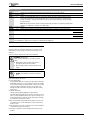
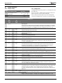
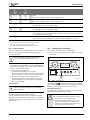
User instructions Wall hung gas-fired condensing boiler Worcester Commercial Boiler Series GB162-50/65/80/100 6 720 648 726-000.1TD For central heating systems and indirect fed domestic hot water 6720813172 (2015/04) UK/IE preface 10.3 Identifying and resetting faults . . . . . . . . . . . . . . . . . . . . 9 preface Please read these instructions carefully These instructions are applicable to the Worcester, Bosch Group boiler model stated on the front cover only. 11 Tips on energy saving . . . . . . . . . . . . . . . . . . . . . . . . . . . . . . . . . 10 These instructions apply in the UK/IE only and must be followed except for any statutory obligation. 12 Environment / disposal . . . . . . . . . . . . . . . . . . . . . . . . . . . . . . . 10 After installation please leave this User instruction Manual, Installation, Commissioning and Servicing Instructions and completed Benchmark Checklist with the user. Dedicated to heating comfort Thank you for purchasing a Worcester GB162 gas-fired condensing boiler manufactured by Worcester, Bosch Group. The company prides itself on manufacturing boilers to the strictest quality control standards throughout every stage of production. 13 Your Guarantee . . . . . . . . . . . . . . . . . . . . . . . . . . . . . . . . . . . . . . 11 1 Key to symbols and safety instructions 1.1 Key to symbols Warnings Warnings in this document are framed and identified by a warning triangle which is printed on a grey background. Worcester, Bosch group has led the field in innovative boiler design and performance for over 50 years. This heritage means all our products are of exceptional quality and proven reliability. The Worcester commercial range in particular is extremely energy efficient, offering you economical running costs and value for money. Electrical hazards are identified by a lightning symbol surrounded by a warning triangle. There is also the reassurance of our no-nonsense 2 years parts and labour guarantee. Contents 1 Key to symbols and safety instructions . . . . . . . . . . . . . . . . . . . 2 1.1 Key to symbols . . . . . . . . . . . . . . . . . . . . . . . . . . . . . . . . . 2 1.2 safety precautions . . . . . . . . . . . . . . . . . . . . . . . . . . . . . . . 2 2 General Information . . . . . . . . . . . . . . . . . . . . . . . . . . . . . . . . . . . 3 3 Energy efficiency . . . . . . . . . . . . . . . . . . . . . . . . . . . . . . . . . . . . . 3 4 Overview of the BC10 basic controller . . . . . . . . . . . . . . . . . . . 4 Keywords indicate the seriousness of the hazard in terms of the consequences of not following the safety instructions. • NOTICE indicates that material damage may occur. • CAUTION indicates that minor to medium injury may occur. • WARNING indicates that serious injury may occur. • DANGER indicates possible risk to life. Important information 5 Service Clearances . . . . . . . . . . . . . . . . . . . . . . . . . . . . . . . . . . . . 4 6 Maintaining your Boiler . . . . . . . . . . . . . . . . . . . . . . . . . . . . . . . . 5 Important information in cases where there is no risk of personal injury or material losses is identified by the symbol shown on the left. It is bordered by horizontal lines above and below the text. Additional symbols Symbol ▶ • – 7 8 9 Explanation of the control unit . . . . . . . . . . . . . . . . . . . . . . . . . . 5 7.1 General . . . . . . . . . . . . . . . . . . . . . . . . . . . . . . . . . . . . . . . 5 Operating the heating system . . . . . . . . . . . . . . . . . . . . . . . . . . . 6 8.1 Menu structure . . . . . . . . . . . . . . . . . . . . . . . . . . . . . . . . . 6 8.1.1 Normal Operation menu . . . . . . . . . . . . . . . . . . . . . . . . . . 6 8.1.2 Manual Operation menu . . . . . . . . . . . . . . . . . . . . . . . . . . 6 Meaning a step in an action sequence a reference to a related part in the document or to other related documents a list entry a list entry (second level) Table 1 1.2 safety precautions INTENDED USE This boiler is only to be used to heat heating system water and for the domestic hot water (DHW) supply e. g. in residential and light commercial properties. It can also be integrated into a cascade system (where several boilers are interconnected). The boiler has been factory-fitted with the BC10 basic controller and the “Universal Burner Automat 3” (UBA 3). Extreme Cold Weather . . . . . . . . . . . . . . . . . . . . . . . . . . . . . . . . . 7 10 Display information . . . . . . . . . . . . . . . . . . . . . . . . . . . . . . . . . . . 8 10.1 Display readings . . . . . . . . . . . . . . . . . . . . . . . . . . . . . . . . 8 10.2 Display codes . . . . . . . . . . . . . . . . . . . . . . . . . . . . . . . . . . 8 10.2.1 Fault or Breakdown . . . . . . . . . . . . . . . . . . . . . . . . . . . . . . 9 2 6720813172 (2015/04) General Information CE label The appliance complies with the basic requirements of the relevant European directives. If you smell gas! ▶ Call the National Gas Emergency Service on: 0800 111 999 ▶ Extinguish any naked flames ▶ Do not smoke or strike matches ▶ Do not turn electrical switches on or off ▶ Open doors and windows ▶ Keep people away from the affected area ▶ Turn off the gas control valve at the meter Conformity has been substantiated by the proper documents which together with the declaration of conformity - are filed with the manufacturer. Boiler Operation This boiler must only be operated by a responsible adult who has been instructed in, understands and is aware of the boiler's operating conditions and effects. Combustible and Corrosive Materials Chemically aggressive substances can corrode the boiler and invalidate any warranty. Abbreviations • CH (boiler) flow = Central Heating flow • CH return = Central Heating return • DHW outlet = Domestic Hot Water warm outlet • MCW inlet = Mains Cold Water inlet • UBA 3 = Universal Burner Automat 3. 2 Servicing ▶ Do not store or use any combustible materials (paper, thinners, paints etc.) inside or within the vicinity of the boiler. Fittings and Modifications Only a competent engineer in accordance with the Gas Safety (Installation and Use) Regulations can remove the outer case and carry out any work. ▶ Do not open the appliance. Any misuse or unauthorised modifications to the boiler, flue or associated components and system will invalidate the warranty. ▶ Do not modify the boiler or flue system in any way. Worcester, Bosch Group accepts no liability arising from any such actions. This does not affect your statutory rights. 3 General Information Ensure that the service engineer completes the Service Record after each service. The Installation Checklist and service interval record can be found at the rear of the Installation, Commissioning and Servicing Instructions. ▶ The boiler must be serviced regularly by a competent, qualified person, such as a Worcester service engineer or other Gas Safe registered engineer. ▶ Always use original spares, to help maintain the economy, safety and reliability of the boiler and have the Service Record completed in the Installation Checklist. Energy efficiency The following product data satisfy the requirements of the EU Regulations No. 811/2013, No. 812/2013, No. 813/2013 and No. 814/2013 supplementing Directive 2010/30/EU. Product data Product type Condensing boiler Rated heat output Seasonal space heating energy efficiency Energy efficiency class Useful heat output At rated heat output and high temperature regime 1) At 30 % of rated heat output and low temperature regime 2) Useful efficiency At rated heat output and high temperature regime 1) At 30 % of rated heat output and low temperature regime 2) Auxiliary electricity consumption At full load At part load In standby mode Other items Standby heat loss Ignition burner power consumption Emissions of nitrogen oxides Sound power level, indoors Symbol – Unit – 7736700642 7746900822 GB162-50 GB162-65 G20 G20 Yes Yes 47 61 93 92 A A 87470248 GB162-80 G20 Yes 82 – – 87470250 GB162-100 G20 Yes 95 – – – Prated ηs – – kW % – P4 P1 kW kW 46.6 15.4 60.5 20.1 82.0 26.6 94.5 31.6 η4 η1 % % 87.3 97.3 87.3 97.3 88.2 97.3 88.4 98.3 elmax elmin PSB kW kW kW 0.045 0.021 0.008 0.073 0.019 0.004 0.100 0.024 0.008 0.145 0.027 0.008 Pstby Pign NOx LWA kW kW mg/kWh dB(A) 0.085 0.000 15 54 0.082 0.000 36 60 0.082 0.000 42 – 0.082 0.000 49 – Table 2 Product data for energy consumption 1) High-temperature regime means 60 °C return temperature at heater inlet and 80 °C feed temperature at heater outlet. 2) Low temperature means for condensing boilers 30 °C, for low-temperature boilers 37 °C and for other heaters 50 °C return temperature (at heater inlet). 6720813172 (2015/04) 3 Overview of the BC10 basic controller 4 Overview of the BC10 basic controller 11 10 1 2 9 3 8 4 5 7 [1] [2] [3] [4] [5] [6] [7] [8] [9] [10] [11] Mains switch (boiler On/Off) c “Reset” button (fault reset button) d Chimney sweep button (for manual operation) e Service button Service Connector G “Burner LED” (On/Off) R “Heat demand” LED Maximum CH (boiler) flow temperature dial Display (for status indication) S “DHW mode” LED DHW temperature dial 6 6 720 648 727-001.1TD Fig. 1 BC10 basic controller 5 Service Clearances The boiler must be located in an area with the following service clearances. 0 mm 0 mm 250 mm (100 mm below pump group) 40 mm 550 mm 6 720 648 727-002.1TD Fig. 2 Clearances Your installer will have provided adequate space around the boiler for safety and servicing access. CAUTION: Restricted space. The boiler may overheat. ▶ Do not restrict this space with the addition of cupboards, shelves etc. next to the boiler. 4 6720813172 (2015/04) Maintaining your Boiler 6 Maintaining your Boiler Your new gas-fired boiler represents a long term investment in a reliable, high quality product. In order to realise its maximum working life, and to ensure it continues to operate at peak efficiency and performance, it is essential that your boiler receives regular servicing and maintenance checks from a competent person beyond the initial 2 year guarantee period. If your gas-fired boiler should fail to operate correctly or requires servicing please contact Worcester, Bosch Group Appointments Team (see rear cover for details). 7 Explanation of the control unit 7.1 General The boiler is fitted with a control unit, the BC10 basic controller ( fig. 1). This controller can be used to control the heating system. If your heating system consists of several boilers (cascade system), you have to carry out the settings on the control units of all individual boilers. ▶ Push on the control panel to open it ( fig. 3). [5] [6] [7] [8] [9] [10] [11] Service Connector G “Burner LED” (On/Off) R “Heat demand” LED Maximum CH (boiler) flow temperature dial Display (for status indication) S “DHW mode” LED DHW temperature dial Mains switch The mains switch ( fig. 4, item 1) is used to switch the boiler on and off. “Reset” button If a fault has occurred you may have to restart the boiler by pressing the “Reset” button ( fig. 4, item 2). This is only required in the event of a “locking” fault. “Blocking” faults are reset automatically as soon as their cause has been removed. The display shows “rE”during the reset operation. “Chimney sweep” button The “Chimney sweep” button ( fig. 4, item 3) is used to put the boiler into manual operation mode, e.g. if the heating system control (e.g. room controller) is defective. The heating system can be operated in manual mode, independent of a room controller on a temporary basis. The control system must comply with Part L1 + L2. In this case, the CH (boiler) flow temperature setting of the right-hand dial is used as the temperature for boiler operation. See table 5 “Manual Operation menu”. DANGER: Damage to the installation due to freezing while manual operation is switched on. After a power failure or after switching off the supply voltage, the heating system may freeze since manual operation is no longer active. ▶ Re-activate manual operation after switching on the heating system, so that the system is permanently in operation (especially if there is a risk of freezing). 6 720 648 727-010.1TD Fig. 3 Opening the control panel The BC10 basic controller is located on the left, behind the control panel. The BC10 basic controller consists of the following components: 11 10 9 8 7 “Service” button The “Service” button ( fig. 4, item 4) is used to display the current CH (boiler) flow temperature, the current working pressure etc. Also see section 8.1.1, page 6. Service Connector A Worcester service engineer can connect a Service Tool here ( fig. 4, item 5) for diagnostic purposes when servicing. “Burner” (On/Off) LED The “Burner” (On/Off) LED ( fig. 4, item 6) lights up when the burner of the boiler is switched on and it is extinguished when the burner is switched off. The “Burner” (On/Off) LED indicates the burner status. LED Status Explanation On Burner Boiler water is being heated. operational Off Burner off The CH (boiler) flow temperature has reached the set temperature or there is no heat demanded. 1 2 3 4 5 6 Table 3 Meanings of “Burner” (On/Off) LED indications 6 720 648 727-001.1TD Fig. 4 [1] [2] [3] [4] BC10 basic controller Mains switch (boiler On/Off) c “Reset” button (fault reset button) d Chimney sweep button (for manual operation) e Service button 6720813172 (2015/04) “Heat demand” LED The “Heat demand”LED ( fig. 4, item 7) lights up when the control system has made a heat demand and it is extinguished when this heat demand is no longer required. 5 Operating the heating system Maximum CH (boiler) flow temperature dial The maximum CH (boiler) flow temperature ( fig. 4, item 8) is used to set the upper CH (boiler) flow temperature limit. The unit is °C. 4 DANGER: Damage to the installation with underfloor heating: by the floor being overheated. ▶ Limit the maximum CH (boiler) flow temperature using the “CH (boiler) flow temperature” dial ( fig. 4, item 8) to the permissible flow temperature of the floor heating circuit (usually maximum 40 °C). Display The heating system status and values can be read out from the display ( fig. 4, item 9). If a fault occurs the display will immediately show the accompanying fault code. The fault code display will flash if a locking fault is detected. “DHW mode” LED The “DHW mode” LED ( fig. 4, item 10) lights up when a DHW request has occurred and it is extinguished when this DHW request is no longer required. DHW temperature dial The DHW temperature dial ( fig. 4, item 11) is used to select the required temperature of the hot water in the hot water cylinder. The unit is °C. This is only active with certain Bosch controls. 8 Operating the heating system 8.1 Menu structure You can navigate through the menu structure of the central boiler on the BC10 using the “Reset” button, the “Chimney sweep” button, the “Service button” ( fig. 6, items 1, 2 and 3) and the display ( fig. 6, item 4) in accordance with the menus in tables 4, 5 and. 1 2 3 6 720 619 373-18.1TD Fig. 5 BC10 basic controller 8.1.1 Normal Operation menu Information about the operating status of the boiler can be displayed via this menu. The currently measured values of the CH (boiler) flow temperature (permanent indication), the working pressure and the operating codes are shown. Proceed as follows: Normal operation menu Step 1 [\/2/4| Display value. Currently measured CH (boiler) flow temperature in °C. Also see section 10.1, page 8. Step 2 Continue in Normal operation menu? Yes: step 3 No: step 1 Step 3 Press the e button. Step 4 [p/1.6| Display value. Currently measured system pressure in bar. Also see section 10.1, page 8. Step 5 Press the e button. Step 6 [-/h/\| Random display code. In this case: Operating phase: Boiler in heating mode. Also see section 10.2, page 8. Step 7 Have at least 5 seconds passed without a Yes: step 1 button being pressed and/or has the mains No: step 8 voltage been interrupted ? Step 8 Press the e button. step 1 Table 4 Normal operation 8.1.2 Manual Operation menu In manual mode, the heating system can be operated independent of a room controller (e. g. RC35). Re-start manual operation after switching on the heating system, so that the system is permanently in operation (especially if there is a risk of freezing). Manual operation menu Step 1 [\/2/4| Display value. Currently measured CH (boiler) flow temperature in °C. Also see section 10.1, page 8. Step 2 Activate manual operation? Step 3 To activate manual operation: Press and hold the d button for more than 5 seconds. Step 4 [\/2/4} Yes: step 3 No: step 1 Display code: Operating phase: As soon as a flashing dot is shown in the right-hand bottom corner of the display, manual operation is active. This means that the boiler is permanently in heating mode. The maximum CH (boiler) flow temperature as set on the maximum CH (boiler) flow temperature dial of the BC10 basic controller (control panel) now applies. The “Heat request” LED lights up. Table 5 Manual operation 6 6720813172 (2015/04) Extreme Cold Weather Manual operation menu Step 5 Press the e button. Step 6 [p/1.6} Step 7 Press the e button. Step 8 [-/h//} Step 9 Note: If the boiler performance has been changed temporarily, this must be set again after ending manual operation, according to the “Settings” menu (table, page). Press the e button. Step 10 [\/2/4} Step 11 Has there been a power failure? Step 12 Deactivate manual operation? Step 13 Display value. Currently measured system pressure in bar. Also see section 10.1, page 8. Display code: Operating phase: Also see section 10.2, page 8. The boiler is in manual operation mode. This means that the boiler is in heating mode while there is no heat request from the controller. During manual operation the “Settings” menu (table from step 3) can be used to temporarily change the target boiler performance. Display value. Currently measured CH (boiler) flow temperature in °C. Also see section 10.1, page 8. To deactivate manual operation: Press and hold the d button for more than 2 seconds until the dot disappears. Yes: step 1 No: step 12 Yes: step 13 No: step 5 step 1 Table 5 Manual operation 9 Extreme Cold Weather In instances where the condensate pipe work is run external or in an unheated area, such as a garage, it can be at risk of freezing, even if insulated. A frozen condensate pipe will cause the boiler to shut down. WARNING: Falling hazard! Failure to follow this guidance can result in personal injury. ▶ Only attempt to thaw a condense pipe that is at ground level, which is easily accessible. ▶ Never attempt to thaw a condense pipe which is at height. CAUTION: Pipe damage ▶ DO NOT use boiling water to thaw the condensate pipe! If the condensate pipe has frozen: ▶ Locate the blockage. It is likely that the pipe is frozen at the most exposed point external to the building or where there is some obstruction to flow. This could be the open end of the pipe, at a bend or elbow, or where there is a dip in the pipe in which condensate can collect. The location of the blockage should be identified as closely as possible before taking further action. ▶ Thaw the frozen pipe. The pipe can be thawed by applying a hot water bottle, a microwaveable heating pack (the sort used for muscular aches and pains) or a cloth soaked in hot water to the exterior of the pipe, close to the point of blockage. Hot water can also be poured onto the pipe from a watering can or similar container. ▶ Once the pipe has been thawed the boiler must be reset, press the reset button for five seconds and wait two to three minutes for the boiler to restart. ▶ If the boiler does not restart, contact Worcester’s Technical Support Team (0330 123 3366) for assistance. ▶ Contact your installer in order to find a permanent solution to the problem. 6720813172 (2015/04) 7 Display information 10 Display information 10.1 Display readings 10.2 Display reading Key to display reading Current CH (boiler) flow [\/2/4| temperature. [p/1.6| Unit Range °C [\/\/0| – [1/3/0| bar [\/0.0| – [p/4.0| Current system pressure. Display codes The display shows the operating condition (e. g. a fault) by means of two three-digit codes. Refer to section 10.3, “Identifying and resetting faults” on page 9 for further instructions on how to remedy certain faults. Please contact your heating engineer if you cannot remedy a fault yourself or if the display shows a code which is not listed in the table. Table 6 Display readings Display code z Main display code e [\/-/\| e [-/a/\] z [-/h/\| z Operating phase: e 1) e Sub display code Communication test while starting up. This display code flashes five times within 5 seconds while starting up to indicate that the communication between the UBA 3 and the BC10 basic controller is being tested. If a new UBA 3 or a new KIM was fitted, this code will flash for max. 10 seconds. Operating phase: [2/0/8| 2) e The boiler is in flue gas test or service mode. Operating phase: [2/0/0| 2) e [-/h/} e 3) e [=/h/\| The boiler is in heating mode. Operating phase: [2/0/0| 2) e The boiler is in manual operation mode. Operating phase: [2/0/1| 2) e [=/h/\| e The boiler is in heating mode. Operating phase: [2/0/1| 2) e [0/a/\| e Pump run-over time via the external hot water cylinder 130 seconds at the minimum speed. The “Burner” LED (On/Off) is off. Operating phase: [2/0/2| 2) e [0/a/\| e The switch optimization program is activated. This program is activated if there has been any demand more frequently than once every 10 minutes. This means that the boiler cannot be restarted until at least 10 minutes have elapsed since initial burner start-up. Operating phase: [3/0/5| 2) e [0/c/\| e The boiler cannot start up temporarily after a DHW request has ended. Pre-operative phase: [2/8/3| 2) e [0/e/\| e The boiler prepares for a burner start-up whenever a heat demand or a DHW request arises. Readiness for operation: [2/6/5| 2) e [0/h/\| e The boiler is in ready mode. There is a current heat demand, but too much energy has been supplied. Readiness for operation: [2/0/3| 2) e [0/l/\| e The boiler is in ready mode. There is no current heat demand. Ignition phase: [2/8/4| 2) e [0/u/\| e The gas valve is activated. Start-up phase: [2/7/0| 2) e [0/y/\| e The boiler starts up after activation of the mains power supply or completion of a system reset. This code is displayed for a maximum of 4 minutes. Operating phase: [2/0/4| 2) e [2/e/\| e [2/0/7| 2) [8/8/8| e The flow temperature sensor has detected that the current flow temperature is higher than the flow temperature setting on the BC10, or that it is higher than the flow temperature. Calculated according to heating requirements, or that it is higher than the flow temperature calculated for the DHW mode. Fault: The system pressure is too low (less than 0.2 bar). Function test: Display test during start-up phase. The display code is displayed for a maximum of 1 second. Table 7 Display codes 8 6720813172 (2015/04) Display information Display code z e Main display code [a/1/1| z e Sub display code [8/0/2| z e Fault: e Time not set. Failing time setting, e.g. due to a long power cut. Fault: 2) e [a/1/1| e [8/0/3| 2) [h/\/7| Date not set. Failing date setting, e.g. due to a long power cut. Operating phase: The system pressure is too low (less than 1.0 bar). e [h/\/7| e Operating phase: [p/-.-| The system pressure is too low (less than 1.0 bar). Operating phase: [\/r/e| The system pressure is too high (over 4.0 bar) or the pressure sensor has not detected a system pressure (boiler functioning normally). Fault: Reset is carried out. After pressing the “Reset” button this code is displayed for 5 seconds. Table 7 Display codes 1) Any indication with a permanent dot in the bottom right-hand corner 2) Only visible on the Service Tool or a specific RC regulator. 3) Any indication with a flashing dot in the bottom right-hand corner. 10.2.1 Fault or Breakdown This boiler is supported in the UK and Eire by Worcester, Bosch Group. 10.3 Identifying and resetting faults Specialist Service Engineers are available to attend a breakdown occurring on this boiler. ▶ Press the “Reset” button ( fig. 6, item 1) for approx. 5 seconds to reset the fault. Fault messages can be identified by the flashing display: Invoices for attendance and repair work carried out on this boiler by any third party will not be accepted. • No charge will be made for parts and/or labour providing: A boiler fault is found and the appliance has been installed within the past 24 months. Reasonable evidence of this must be supplied on request. i.e. the Benchmark Checklist. • A call-out charge will be made where: – The boiler has been installed for over 24 months. – Evidence cannot be provided that the first year service inspection has been carried out (i.e. an entry in the Benchmark Checklist). – Our Field Service Engineer finds no fault with the boiler. – The cause of breakdown is misuse or with other parts of your plumbing/heating system, or with equipment not supplied by Worcester, Bosch Group. Technical Support No boiler fault is found on over 30% of all service calls. In the case of a suspected fault, refer to the fault finding section of this guide. In the event of a boiler fault or breakdown please contact Worcester, Bosch Group appointments team on 0033 123 9339. Your advisor will arrange for an engineer to call with the minimum of delay; under normal circumstances this will be from 1 - 3 working days (excluding weekends) for priority breakdown situations (no hot water and/or heating). 6720813172 (2015/04) 1 6 720 619 373-22.1TD Fig. 6 BC10 – “Reset” button The display shows [\/r/e|. The boiler tries to reset the fault. If the display shows a normal operating code afterwards, the fault has been remedied. Otherwise, please repeat the reset two or three more times. If the fault cannot be reset If the fault remains and cannot be cleared by pressing the reset button, contact Worcester, Bosch Group for assistance. CAUTION: Damage to the installation. In frost conditions, the heating system may freeze up if it is not operational, e. g. due to a power failure. ▶ If the heating system is switched off for a couple of days due to a fault and there is a risk of frost, the heating water must be drained at the lowest point of the system to prevent it from freezing. 9 Tips on energy saving 11 Tips on energy saving HEATING ECONOMICALLY The boiler provides a high level of comfort whilst keeping gas consumption and the environment effects as low as possible. The gas supply to the burner is controlled according to the level of demand for heat. The boiler operates with a low flame if the demand for heat reduces. The technical term for this process is modulating control. Modulating control reduces temperature fluctuations and provides an even distribution of heat throughout the home. This means that the boiler may stay on for relatively long periods of time but will use less gas than a boiler that continually switches on and off. CENTRAL HEATING SYSTEMS WITH ROOM THERMOSTAT/ THERMOSTATIC RADIATOR VALVES With modern heating systems set around a 20 °C heat loss, the optimum setting for a condensing boiler will be approximately between one and two on the central heating temperature control. The system must be balanced correctly and the radiators may need upgrading. This allows the boiler to condense as much as possible for the central heating system. 12 Environment / disposal Environmental protection is a fundamental corporate strategy of the Bosch Group. The quality of our products, their economy and environmental safety are all of equal importance to us and all environmental protection legislation and regulations are strictly observed. We use the best possible technology and materials for protecting the environment taking account of economic considerations. Packaging We participate in the recycling programmes of the countries in which our products are sold to ensure optimum recycling. All of our packaging materials are environmentally compatible and can be recycled. The temperature of each room can be set individually (except primary room with the room thermostat) using the thermostatic radiator valves. ROOM THERMOSTATS Reducing the setting of the room thermostat by 1 °C can reduce fuel consumption by up to 10%. NEW CONTROL SYSTEMS Upgrade your heating control system if necessary with the latest equipment available. The minimum level of control is a programmer, interlocking room thermostat and thermostatic radiator valves. ROOF INSULATION Around 30% of the heat loss from a property is through the roof. Replace any old insulation with new insulation, preferably of around 200 mm thickness or more. WINDOW FRAMES Single glazed windows, particularly those with steel frames, can lose a great deal of heat. Consideration should be given to replacement with PVCu or wooden framed double glazed units. RADIATORs If a radiator is sited underneath a window, its performance will be affected if the curtains are allowed to drape over the radiator. Shelves fitted above or in front of the radiator should also be avoided. It is advisable to manually adjust all thermostatic radiator valves every 2 - 3 months to prevent them sticking. Ensure radiator valves are correctly set and not damaged. DRAUGHTS Try to ensure that draughts around doors, windows, letterboxes and keyholes etc. are reduced by using a suitable draught excluder. WARNING: AIR VENTS ▶ Do not block or seal any air vents that are installed to ensure that the central heating boiler operates safely. CURTAINS Lined curtains, or heavier full length curtains can provide excellent insulation. However, always ensure that the curtains do not drape over radiators. 10 6720813172 (2015/04) Your Guarantee 13 Your Guarantee This boiler is guaranteed against faulty materials or workmanship for a period of 2 years from the date of installation subject to the following terms and conditions. • During the period of this guarantee any components of the boiler which are proven to be faulty or defective in manufacture will be exchanged or repaired free of charge by Bosch Thermotechnology Ltd.. • The householder may be asked to prove the date of installation, that the boiler was correctly commissioned and, where appropriate, the first year‘s service has been carried out to the satisfaction of Bosch Thermotechnology Ltd. when requested. These should be part of the Installation Checklist. • The boiler has been used only for the purposes for which it was designed. This guarantee does not affect your statutory rights. GUARANTEE REGISTRATION Returning the card will register you as the owner of your new gas boiler and will assist us in maintaining an effective and efficient customer service by establishing a reference and permanent record for your boiler. For your own record: Please ensure that the Installation Checklist has been completed by your installer or service engineer. Model Serial No.1) Type/size Date of installation Name of Installer Telephone number of Installer Table 8 1) See identity label on the top of the appliance. 6720813172 (2015/04) 11 WORCESTER, BOSCH GROUP: Worcester, Bosch Group Cotswold Way, Warndon, Worcester WR4 9SW. Tel. 0330 123 9559 Worcester, Bosch Group is a brand name of Bosch Thermotechnology Ltd. worcester-bosch.co.uk 6720813172 TECHNICAL SUPPORT: 0330 123 3366 APPOINTMENTS: 0330 123 9339 SPARES: 0330 123 9779 LITERATURE: 0330 123 9119 TRAINING: 0330 123 0166 SALES: 0330 123 9669