1
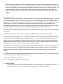
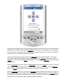
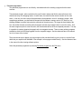
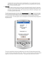
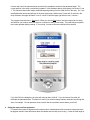
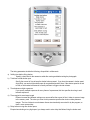
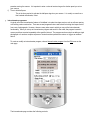
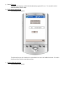
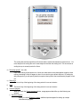
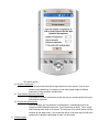
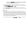
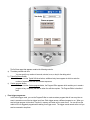
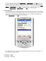
AutoMate User Manual
Overview
This manual assumes that AutoMate will be used for still photography. The application of AutoMate is not strictly
limited to still photography, however. It can be used with searchlights, as a remote control for positioning hard-to-reach
studio lights, for telescopes, or spotting scopes. A movie camera could as easily be mounted to the robot as a still
camera. There are many video camera applications, including creating pre-programmed camera motion sequences or
filming wedding ceremonies by remote control with the camera mounted above and behind the altar. The inventive
person can find any number of uses for this device, including building robots and programmable motor-driven toys or
Halloween animatronics. The applications are limited only by the imagination.
AutoMate integrates all of the following in a small lightweight package:
A motorized, programmable 2D (pan-tilt) camera robot, ideal for making gigapixel panoramas
A programmable electronic shutter release with both full-press and half-press output
An intervalometer that can do more than take photos
A programmable self-timer
An event-sensing system that can execute custom programs based on input from two trigger signals
A driver line for operating external devices
A remote control for aiming the camera, activating the meter, and firing the shutter
A custom program editor
A collection of user-updateable presets and custom programs
AutoMate components
AutoMate consists of two components, a robot and software that runs on a hand-held controller, such as a PDA or cell
phone
1. The robot
The robot is the machine that you mount on a tripod and on which you mount a camera. The robot’s primary
function is to execute programs that you send to it from the hand-held via Bluetooth. The programs you send cause
the robot to move the camera, fire the camera’s shutter, sense inputs from external triggers, turn the LED on and
off, and to operate an external device of your choosing. The robot includes a micro-controller that interprets the
programs sent to it from the hand-held. The robot is compact and light. The connection between the camera and
the robot is a cable that is specific for the camera. For cameras that have wired remotes, the shutter cable plugs
into camera’s remote control port. For cameras that have infrared remote controls, the cable has an infrared LED
you attach to the camera close to the infrared sensor. If you have more than one type of camera, you can purchase
a cable for each camera. More than one camera can be fired at a time by using a T connector. Cameras with
neither infrared nor electronic remote controls are not supported at this time.
2. The hand-held controller
The Gadget Works does not provide the hand-held controller at this time but we do provide the software that runs
the hand-held controller. The software runs on any PDA running Windows Mobile, version PocketPC 2003 or later.
A Java version is in development. You tell the robot what to do by using the graphical user interface of the handheld controller to specify what you want it to do. The hand-held takes your input and generates a program that it
sends to the robot via Bluetooth, where it is stored and executed. When you create a program for the robot or set
camera or timing parameters, you can save those parameters for later loading. The program always remembers the
most recently saved values and programs and automatically reloads them the next time you start the program. The
controller software provides both a simple and an advanced mode for most programs that you can create. The
simple mode presents the most common choices and the advanced mode allows you to create a complex custom
program.
About the robot
The front of the robot has a power switch, three mini-jacks, an LED, and a connector for a Bluetooth antenna. The three
mini-jacks are labeled A, B, and C. Mini-jack A is where you plug in the cable that connects to your camera’s remote
control port. Mini-jack B is a powered output port that has +5, ground, and a signal line. You use mini-jack B to control
external devices. Mini-jack B is deliberately a different size than mini-jack A so that you don’t accidentally plug a
powered cable into your camera. Mini-jack C is an input port for sensing external trigger signals. It contains two signal
lines and a ground. No danger can come from accidentally plugging your camera cable into mini-jack C.
The power switch has a stand-by position that has no real function at this time. Use only the full on and full off positions
of the switch.
The Bluetooth antenna connector allows you to attach a standard Bluetooth antenna for extended range.
At the rear of the robot is the battery case. It holds four AA batteries. The correct orientation of the batteries is clearly
marked inside the case. The batteries can be rechargeables or not. You can change batteries on the robot on the fly
without losing any running programs and without breaking the Bluetooth link by plugging a special emergency backup
battery pack into the power socket on the side of the robot while you swap in a fresh set of batteries. Once the fresh
batteries have been inserted, you can remove the emergency backup battery.
The platform on which you mount your camera contains a standard tripod mounting bolt, which is ¼ 20 thread size. You
can conceivably mount the camera facing either toward the battery case or toward the front plate, but the AutoMate
program assumes that tilting up means tilting the platform edge closest to the battery case up, not the other way
around.
It is important, especially for panoramas, to mount the robot on the tripod such that it is level. The bubble level on the
robot’s case can be used to facilitate making the robot level.
Using the hand-held controller
The hand-held controller has several modes, including:
Remote controller
The remote controller allows you to rotate the camera in two dimensions and to fire the camera’s shutter. The
functionality for the remote is on the opening screen, as shown in the following illustration:
The opening screen appears when you start the program and when you return from any of the programming or
editing pages. The opening screen contains Directional buttons that you use to manually move the robot right,
left, up, and down. There are also buttons to fire the shutter and half-press the shutter release. To operate the
controls you must be connected to the robot via Bluetooth.
The larger semi-circular button in the center of the Directional buttons array fires the shutter. The smaller
semi-circular button sends the half-press shutter signal. There is also a Continuous check box control and a
Percent slider. The function of the Percent slider depends on the setting of the Continuous check box control, as
described below.
When the Continuous check box is checked, the Directional buttons and the Percent slider are put in continuous
mode. When in continuous mode, the robot rotates or tilts for as long as you continue to press a Directional
button. The Percent slider functions as a motor speed control when in continuous mode.
When the Continuous check box is unchecked, the Directional buttons function in frame mode. Every time you
tap a directional button in frame mode, the robot moves some percentage of one frame. The Percent slider sets
the percentage of one frame to move when in frame mode. The number of degrees of motion for one frame is
dependent upon the Camera/Lens setting, as explained later in the manual.
Panorama programmer
The panorama programmer is a user-friendly, automated method for creating a program that the robot
executes.
The panorama program, when executed on the pan-tilt robot, rotates and tilts the camera through a twodimensional array of overlapping frames. At each frame, the robot fires the camera’s shutter one or more
times. In this way, the entire scope of the panorama is photographed in a set of overlapping images. After
completing a panorama, you download the images from the camera’s memory card to a PC where you use
stitching software to make a high resolution composite of the entire scene. The longer the focal length of the
lens, the smaller the area covered by each photograph, and the more images it takes to cover the scene. And
the more images required to cover the scene, the more detailed will be the final composite panorama. This way
it is possible to create a gigapixel photograph with a six megapixel camera. There are many stitching programs
available to stitch the final image together from the composite images. See the references later in the manual
for a list of some of the choices.
There are several ways to display very large images on the web that allow the user to zoom in to see the finest
detail that you captured with AutoMate. One example is a free program called Zoomify. See the references later
in the manual for other viewing software options.
Select the panorama programmer by choosing Panorama program from the Edit menu.
a)
b)
c)
d)
e)
f)
g)
The panorama programmer page contains values that you specify. You can also load values that you saved
previously. These parameters include the following:
Scene width
The horizontal dimension of the scene in degrees
Scene height
The vertical dimension of the scene in degrees
Horizontal overlap
The number of degrees each image should overlap the images to its right and left
Vertical overlap
The number of degrees each image should overlap the images above and below it
Exposures / frame
The number of exposures to take at every position
Precedence
How to move the camera through the two dimensional array of frames, including:
i) By row
The robot rotates through a complete row of frames before moving to the next row.
ii) By column
The robot tilts through a complete column of frames before moving to the next column .
Starting at
You specify which corner at which you want to start taking photos. You can specify upper left, upper
right, lower left, or lower right. Be certain to position the camera at the specified corner of the scene
before running the panorama program.
h) Motor speed
You can specify the speed at which the motors move the camera through the frames of the panorama.
The value you enter is the percentage of full speed at which both the rotating and tilting motors run for
the duration of the panorama program. When using long lenses over 400 mm in focal length, it is best
to use slower speeds for better control.
To send the panorama program to the robot, select Panorama program from the Run menu on the main page.
Once you send the panorama program to the robot, it saves the program in its memory and begins to execute
it. You do not need to remain connected to the robot after that point unless you anticipate cancelling or
pausing the panorama. Once the program is sent, a screen appears on the hand-held showing the progress of
the panorama shoot.
This screen is generated and continuously updated based on the content of the panorama program and does
not require continued communication with the robot. However, if you choose to pause or cancel the panorama
program, you must remain in Bluetooth communication. The progress screen shows the total number of
columns and rows in the panorama array, as well as the precedence and where the panorama began. The
current position in the array is continuously updated. In the illustration above, the program is at column 6, row
1. The rows and columns are always numbered beginning starting from the initial corner of the array. So, if you
specified that the camera should begin in the lower right corner, and there are 2 rows and 16 columns in the
array of frames, the upper left frame is row 2, column 16 and the upper right frame is row 2, column 1.
The progress screen also has a Stop button. When you click the Stop button, the robot stops what it is doing
and waits for you to either cancel the shoot or to continue it when you are ready. The robot always completes
the current operation before pausing. If it is moving, it moves to the next scheduled frame location.
If you click OK in the dialog box, the robot will continue where it left off. If you click cancel, the robot will
terminate the panorama shoot. This feature is useful if you need to change memory cards part way through the
shoot, for example. You can pause the shoot, insert a new card, and then resume where you left off.
Setting the camera and lens parameters
To compute the number of degrees that the robot needs to rotate between each successive columns and rows,
the program needs to have information about the camera and lens that you are using. It uses the focal length of
the lens, the crop factor of the sensor, the aspect ratio of the sensor, and the orientation of the camera. These
values are all set in the camera settings page, which you display by choosing Camera and Lens from the Edit
menu.
Setting the timing parameters
Certain timing information is required to correctly operate your camera. To set the timing preferences, choose
Timing parameters from the Edit menu:
a)
b)
c)
d)
e)
The timing parameters include the following, all specified in milliseconds:
Settling time before firing shutter
Specify a short time for the camera to settle after moving and before taking the photograph
Total time to hold shutter open
Specify the amount of time to keep the shutter button pressed. If you have the camera’s shutter speed
set to Bulb, you can hold the shutter open for an extended period of time. If the shutter speed is not set
to Bulb, a few hundred milliseconds is usually sufficient to trigger a shutter release.
Time between multiple exposures
If you specify multiple exposures for every frame of a panorama, this time specifies how long to wait
between exposures
Time required to save image to card
Different cameras and different settings on a camera affect the amount of time it takes to save an image
to the memory card. The value you enter for this parameter specifies the minimum delay between
images. The time it takes to move between frames is automatically accounted for by the program, so
there is never excess delay.
Delay before moving after shutter press
Except when shooting at very high speed, you always need to set a delay that follows firing the shutter and
f)
precedes moving the camera. It is important to enter a value at least as long as the shutter speed you set on
your camera.
Time to hold half-press
This is the time required to activate the half-press signal on your camera. It is usually no more than a
few hundred milliseconds, if that.
Intervalometer programmer
A typical use of the intervalometer feature of AutoMate is to make time-lapse movies, such as a flower opening
or a building under construction. There are several programs that are well suited for making time lapse movies
from a set of photographs. However, there are many other uses to which you can put the intervalometer
functionality. When you set up an intervalometer program and send it to the robot, the program is saved in
memory and then executed repeatedly at the specified interval. The program can be as simple as taking a single
photograph or it can be a complex sequence of instructions that operates the motors or triggers an external
device.
To create or modify an intervalometer program, choose Intervalometer program from the Edit menu on the
main page.
The Intervalometer page contains the following controls:
a) Interval: Run every
This value is the frequency at which the intervalometer program will be run. You can set the units in
seconds, minutes, hours, or days.
b) Set the starting date and time
The following screen appears:
The date and time you set is based on the current date in time set in the handheld controller. Be certain
that the controller has the correct date and time.
c) Set the ending date and time
The following screen appears:
The ending date and time specifies the final time that the saved intervalometer program will run. You
must always set an ending time and it must always be later than the starting time. You can choose an
ending time up to several years in the future.
d) Daily sleep period? Yes or No
Often when making a time lapse movie, it does not make sense to take photographs at night or when
nothing interesting is likely to happen or when it is too dark to get a decent exposure. By setting the
daily sleep period, you can specify a daily time period, during which the intervalometer program will not
run.
e) Sleep from:
The time of day of the beginning of the sleep period in hours and minutes
f) Until:
The time of day of the beginning of the sleep period in hours and minutes
g) Choose a program
When you touch the Choose a program button, a page appears that offers you the following two
options:
i) Exposure program
When you choose Exposure program, additional options appear for setting up a simple
intervalometer program:
The options include:
(1) Number of exposures
You may want to take more than a single exposure at every interval. If you set your
camera to auto-bracketing, for example, you can take multiple images at different
exposures by firing the shutter multiple times.
(2) Time between exposures in seconds
If you specify more than one exposure at each interval, you can also specify how long to
wait between exposures.
(3) Precede with wakeup pulse
If you are taking a very long sequence of photographs, it is advantageous to let the
camera turn itself off between exposures, if your camera has the ability. This is usually
called entering sleep mode on the camera. The half-press of the shutter wakes most the
cameras up from sleep mode. If you choose this option, a half-press signal is sent to the
camera prior to taking the photograph to wake it up from sleep.
ii) Custom program
When you touch the Custom program button, the program editor appears. The program editor
is described in more detail later in the manual, but its function is to define a set of commands
that comprise the program that is executed at every interval.
Once you have entered all the parameters for the intervalometer program, you can run it immediately by
choosing Run with these settings from the File menu or you can return to the Main page and run the program at
any time by choosing Intervalometer program from the Run menu.
There are also Save and Load buttons on the Intervalometer page that allow you to save the settings for an
intervalometer program and reload them at another time. To save and load a custom program, use the program
editor.
Self-timer programmer
Most cameras have a self-timer, but for the most part all they do is take a photograph after a given delay.
AutoMate expands on the self-timer concept by adding the ability to program the timer in new and useful ways.
As with the intervalometer and the trigger modes, you create the program that the robot runs when the timer
runs down. There are two modes of program creation. The simple mode lets you set the number of exposures
and the time between exposures. In the simple mode the LED flashes one second before taking each exposure.
In the custom program mode, you use the program editor to create a program that can operate the motors and
activate an external device, in addition to taking photographs.
To create or modify a self-timer program, choose Self-timer program from the Edit menu on the main page:
The Self-timer page that appears contains the following controls:
a) Time delay number and units
You can specify any number of seconds, minutes, hours, or day for the delay period
b) Typical Self-timer button
When you click the Typical Self-timer button, additional entry boxes appear in which to enter the
number of exposures and the time between exposures.
c) Custom program button
When you click the Custom program button, the Program Editor appears which enables you to create a
program of any complexity that will run when the self-timer expires. The Program Editor is described
later.
Event trigger programmer
In the event trigger mode, you use the Program Editor to create a custom program that will run every time an
event is sensed on one of the two trigger input lines. Each trigger causes a different program to run. When you
send a trigger program to the robot, it saves it in memory and waits until an event occurs. You can still use the
robot to run non-triggered programs while waiting for a trigger event. The trigger events remain active until you
send a command to stop them.
To create a trigger event program, choose Trigger Program 1 or Trigger Program 2 from the Edit menu on the
main page. In each case, the Program Editor appears. Use the Program Editor to create the program that you
want to run when the trigger event occurs. The program is not sent to the robot until you choose either Trigger
Program 1 or Trigger Program 2 from the Run menu on the main page. To deactivate a trigger program on the
robot, select Trigger Program 1 or Trigger Program 2 from the Stop menu on the main page.
Custom program editor
The Program Editor is a tool for creating programs that you send to the robot to be executed. Custom programs
can be run at every interval of an intervalometer program, at the end of a self-timer count-down, upon receiving
a trigger signal, or immediately upon sending the program to the robot. You create the custom program by
choosing Custom Program from the Edit menu on the main page.
The Program Editor contains a drop-down list of commands that you can insert into your custom program. The
list of commands includes the following:
a) Move right >> degrees
b) Move right >> frames
c) Move right >> milliseconds
d)
e)
f)
g)
h)
i)
j)
k)
l)
m)
n)
o)
p)
q)
r)
s)
t)
u)
v)
w)
x)
Move left >> degrees
Move left >> frames
Move left >> milliseconds
Move up >> degrees
Move up
>> frames
Move up
>> milliseconds
Move down >> degrees
Move down >> frames
Move down >> milliseconds
Pause milliseconds
Do shutter sequence
Press shutter button
Release shutter button
Do half-press sequence
Half-press shutter
Release half-press
Do loop (count)
End Do loop
Insert program sequence
Wait for trigger 1 signal
Wait for trigger 2 signal
For each of the Move commands, there are three ways to specify how far to move, number of degrees, number
of frames, and milliseconds of time. When you choose any of the Move commands you are prompted to enter
the corresponding value. For many of the commands, a computation is made based upon the camera and lens
settings, the timing parameters, and the calibration values. This computation is performed at the time the
program is sent to the robot. For example, to compute how many degrees there are in a frame, it is necessary
to know the specifics of the camera and lens. And to compute the amount of time to move one degree, it is
necessary to know the calibration figure for milliseconds of motion per degree in the specified direction.
Likewise, a shutter sequence depends on certain timing information on the Timing Parameters page. Therefore,
it is necessary to be certain that you load or set all the appropriate camera, lens, timing, and calibration data
before sending the program to the robot.
The Do loop command must be eventually followed by a corresponding End Do loop command. The robot will
execute all the commands between the Do loop command and End do loop command as many times as you
specify on the Do loop command. You can have a maximum of 5 nested Do loops.
The Insert program sequence command enables you to insert a program that you previously saved. When you
enter a Insert program sequence command, a file open dialog appears that shows all custom programs saved on
the hand-held. The commands from the inserted custom program are directly inserted into the current custom
program. You can insert commands in the middle of an inserted section and you can delete command from
within the section.
You can change the insert point in a program and you can delete a range of commands. All commands are
numbered and the controls for changing the insert point and for deleting a range require you to provide the
appropriate statement numbers.
You can create a custom program for the Intervalometer or the Self-timer or for the two trigger events, as
described earlier in the manual.
Installing the AutoMate software on your PDA
To install the AutoMate software on your PDA, perform the following steps:
1. Attach the PDA to your PC and observe that the PDA file structure appears on your PC .
2. Copy the CAB file from the distribution disk to any folder on the PDA. The Documents folder is as
good as any.
3. Disconnect the PDA from your PC.
4. Click the CAB file icon on the PDA.
A folder named TheGadgetWorks is created inside the Program Files folder and AutoMate 1.0 is
inside the TheGadgetWorks folder.
5. Install Microsoft .NET Compact Framework 2.0 on your PDA if necessary.
On your PDA, navigate to Settings > Memory > Remove Programs and look for Microsoft .NET CF 2.0
in the list of programs in storage memory. If it is present you are all set. If not, perform the
following steps:
1. Download CF 2.0 from http://msdn.microsoft.com/en-us/netframework/aa497280.aspx
2. Attach your PDA to your PC and confirm that you can see the PDA file structure on your PC.
3. Execute the Microsoft download by double clicking on it.
The Microsoft executable installs CF 2.0 on your PDA.
Your first time using AutoMate
The AutoMate program installs itself in the My Device/Program Files/TheGadgetWorks folder on your hand-held
device. To start AutoMate, touch AutoMate 1.0 on the touch screen.
Selecting the correct COM port
When running AutoMate on the hand-held for the first time, the program prompts you to identify the COM port
that your hand-held uses for Bluetooth communications. . On some hand-held devices, there are two COM
ports reserved for Bluetooth, incoming and outgoing. Choose the outgoing port. This information is saved in
the TheGadgetWorks folder in a file with the name BTCOMPort. Once you set this value you will never be
prompted to set it again. However, if you find that you made an error, you can change the value you entered by
choosing Set Bluetooth COM Port from the Run menu.
Connecting to the robot
After specifying the COM port, a screen appears that shows all the Bluetooth devices in the vicinity. If the robot
is not already turned on, turn it on now. A device named AutoMate1.0 should appear on the Bluetooth device
search screen. Choose AutoMate1.0. After a few seconds, the Bluetooth search screen should disappear and
you have successfully made a connection. If you experience any problems with this process, check the manual
for your hand-held device to make sure that you set up your device correctly for finding serial Bluetooth radios.
Setting other parameters
Until you have set and saved various parameters, AutoMate asks you if you want to set them every time you
launch the program. These parameters include camera and lens, timing, and calibration values. If you choose not
to set them, AutoMate temporarily inserts default values for all the parameters, but they are unlikely to be
appropriate for your situation, so you might as well set them correctly at the outset.
Calibrating the motors
Next, AutoMate asks if you want to run the calibration procedure. The calibration procedure determines the
speed of the motors. Calibration is important because AutoMate converts degrees of rotation or tilt into
milliseconds of motor operation. With an accurate calibration, the robot can accurately position the camera
for each frame of a panorama.
AutoMate is preset with calibration values that are in the right range but are probably not accurate enough for
most work. Therefore, you should perform the simple calibration procedure to tweak the values to match the
characteristics of the motors in your robot.
You can run the calibration procedure when asked at startup time or at a later time by choosing Edit >
Calibration values from the main menu. The following screen appears:
The calibration procedure consists of tweaking four values that control the Up, Down, Right, and Left motor
speeds. These values represent milliseconds per degree of travel. Larger values result in more travel for a given
number of degrees. The first step is to test the current values by clicking the Horizontal test and Vertical test
buttons. When you run either test, the robot takes a photo, moves one frame, takes another photo, moves back
one frame, and takes another photo. When the second image exactly abuts the first image, the calibration
value for the first direction is correct. When the third image exactly abuts the second image, the calibration
value for that direction is correct. When both calibration values are correct, the first and third images are
identical and the second image abuts both of them. If the images do not abut, then it might be necessary to
tweak one or more of the values.
Note that the accuracy of the calibration is not highly critical for many applications. For example, if you are
using the robot to photograph panoramas with significant overlap between images, a little inaccuracy is
tolerable. However, if the speed in the left direction does not match well the speed in the right direction,
columns within a panorama array might not be perfectly vertical. If the inaccuracies are small, however, minor
misalignment of columns is not usually a problem because most stitching programs can handle misaligned
columns quite well. The only true requirement is that there is sufficient overlap between images and that there
are no gaps between images.
Running the Calibration tests
To set the calibration values, perform the following steps:
1. Start AutoMate on your PDA
2. Connect the PDA to the robot
3. Click the half-press button to wake up the robot and to assure that a connection exists
4. Choose Edit > Calibration values
5. Set the camera and lens values appropriately for the camera and lens you are using for your test
Be sure to set focal length, aspect ratio, and crop factor
6. Set the overlap percentage to 0
7. Choose a medium focal length lens, such as a 100 mm
8. Mount the camera on the robot and the robot on a tripod
9. Connect the shutter release of the camera to the shutter output port of the robot
10. Choose a wall or surface to photograph
11. Place a ruler or yardstick such that it crosses the border between the first and second images
12. Focus the camera
13. Click the Horizontal test button
The robot takes three photographs, as described above
14. Move the images from your memory card to your computer and display them in an image editing
program
15. Estimate the percent of error in the overlap (or gap) between images and modify the appropriate
speed value accordingly.
16. Perform steps 13-15 until there is an insignificant percent of overlap or gap between the first two
images
17. Perform steps 13-15 until there is an insignificant percent of overlap or gap between images two
and three
18. Do steps 13-17 for the Vertical test
The motor speeds remain quite reliably constant even after several hours of shooting. But batteries do run
down, and at some point, the motors tend to slow down. So, calibrating with fresh batteries and using fresh
batteries for a shoot is always a good idea.
Waking up the robot
Assuming that you connected to the robot successfully, you can begin to use it. The first thing you need to do is
to wake the robot out of its initial state, in which it is checking for a firmware upgrade command. If the first
command that the robot receives via Bluetooth is the firmware upgrade command, it downloads new firmware
from the hand-held before becoming ready for use. To break the robot out of the initial firmware upgrade
checking phase, send it a half-press signal. The half-press button is the smaller of the two partial circles in the
center of the arrows on the front screen. Upon breaking out of the initial phase, the robot flashes its LED three
times very fast. At that point, the hand-held is in communication with the robot and the robot is ready to
receive commands and programs to run.