1
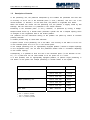
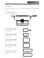
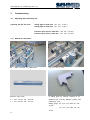
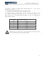
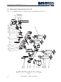
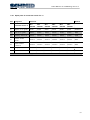
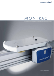
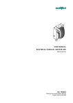
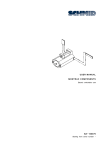
OPERATING INSTRUCTIONS Montrac Positioning Unit PV-2/3 User Manual for Positioning Unit 2/3 508496 ENGLISH Edition: 03/2005 Change index Editions issued so far: Edition Comments Order number 06/2004 Initial edition 508496 2 User Manual for Positioning Unit 2/3 Table of Contents 1 Positioning unit ................................................................................................................ 5 1.1 Directives of the positioning unit which have been fulfilled .................................. 5 1.2 EU conformance (to EC Directive on Machines, Appendix II A) ......................... 5 1.3 Description of function.................................................................................. 6 1.4 Dangers .................................................................................................... 7 1.5 Additional information ................................................................................... 7 1.6 Validity of the User Manual .......................................................................... 8 2 Technical data ................................................................................................................. 9 2.1 Load limits ................................................................................................ 9 2.2 Installation ............................................................................................... 10 2.2.1 Minimum Trac length ................................................................................. 10 2.3 Support on a substructure of Quick-Set® profiles .............................................12 2.4 Support on a flat table top .........................................................................13 3 Commissioning .............................................................................................................. 14 3.1 Adjusting the positioning unit ........................................................................14 3.1.1 Material for adjustment ................................................................................14 3.1.2 Checking the horizontal position of the system: ...............................................15 3.1.3 Adjusting the beam ....................................................................................16 3.1.4 Mechanical check .......................................................................................17 3.1.5 Adjusting the sensors and the air supply........................................................18 3.1.6 Setting the stopping position of the shuttle .....................................................19 3.2 Arrangement of the control cams in single positioning unit ................................ 20 3.3 Arrangement of the control cams in multiple positioning unit .............................. 23 3.4 Additional monitoring and control elements for multiple positioning ....................... 26 3.5 Movement of the shuttle platform due to the indexing process ........................... 27 4 Maintenance .................................................................................................................. 28 4.1 Check the PV with the setting gage ............................................................ 28 4.2 Clean and oil locking slide ......................................................................... 28 4.3 Clean PV ................................................................................................ 28 4.4 Check buffer ............................................................................................ 28 4.5 Wtih pneumatic control elements, check starting vane in the MPV ...................... 28 5 Spare parts for PV-2/3 .................................................................................................. 28 3 User Manual for Positioning Unit 2/3 5.1 Spare parts for PV-2/3 ............................................................................ 28 5.1.1 Spare parts for PV-2/3 ............................................................................ 29 5.2 Spare parts for base structure for PV-2/3 .................................................... 30 5.2.1 Spare parts for base structure for PV-2/3 .....................................................31 5.3 Spare parts for conversion set for PV-2/3 ................................................... 32 5.3.1 Spare parts for conversion set for PV-2 ....................................................... 33 6 Environmental compatibility and disposal ...................................................................... 34 6.1 Surface treatment ...................................................................................... 34 6.2 Shaping processes .................................................................................... 34 6.3 Emissions during operation .......................................................................... 34 6.4 Disposal .................................................................................................. 34 7 List of figures................................................................................................................. 35 4 User Manual for Positioning Unit 2/3 1 Positioning unit 1.1 Directives of the positioning unit which have been fulfilled The directives fulfilled relate to all operating states which may arise in a Montrac transport system and to all functions which the positioning unit has to perform according to the description. 1.2 EU conformance (to EC Directive on Machines, Appendix II A) Regulations and standards taken into account: EC Directive on Machines 98/37/EC Manufacturer: SCHMID Group | montratec AG Zielmattenring 6 4563 Gerlafingen Tel. +41 32 55 88 700 Fax. +41 32 55 88 799 5 User Manual for Positioning Unit 2/3 1.3 Description of function In the positioning unit, the platforms transported by the shuttles are positioned and held with an accuracy of ±0.02 mm in the horizontal plane (x and y direction) and ±0.2 mm in the vertical direction (z direction). At the same time, the platform is supported from below. When the shuttles are moved into the positioning unit, the platform is slighlty raised by ball bearings, with the result that it is positioned in the vertical direction. Positioning in the horizontal plane (x and y direction) is performed by moving a wedgeshaped Pusher driven by a double-action pneumatic cylinder into the V-shaped opening which is arranged on the longitudinal side of the shuttle platform. The presence and the mechanical locking of the platform are polled by means of inductive proximity switches. A dovetail permits fixing to Quick-Set® elements. A special version of the positioning unit is the MPV. The accuracy of the MPV is ±0.03 mm in the horizontal plane and ±0.2 mm in the vertical plane. In the multiple positioning unit, an appropriately equipped platform (several V-shaped openings on the longitudinal side) can be held and positioned several times in succession depending on the chosen spacing. Consequently, it is possible to save one axis in the horizontal plane (in the direction of travel), i.e. a portal axis can be used instead of an XY portal unit or a robot. It is also possible, with an appropriately equipped platform, to perform single positioning in one station of the system and multiple positioning in another station of the system. Versions Single positioning unit Multiple positioning unit Other sizes 1) 2) 3) 6 max. 6 positions possible max. 8 positions possible max. 12 positions possible Platform dimensions Art. No. 200 x 300 mm 55290 300 x 400 mm 55292 200 x 550 mm 55294 200 x 300 mm 55291 1) 300 x 400 mm 55293 2) 200 x 550 mm 55295 3) Max. 400x700 Exo User Manual for Positioning Unit 2/3 1.4 Dangers Danger of crushing in manual workstations with positioning unit, see section on shuttle On moving the shuttle into positioning units which, because of the necessary accessibility (e.g. manual workstation), cannot be made secure by separating, fixed protective devices with locking according to EN 292-2 Section 4.2.2.2 or with locked, separating protective devices with locking according to EN 292-2 Section 4.2.2.3. a), it is essential to reduce the shuttle speed. In order to achieve this, the AB cam is positioned 150 mm before the inlet edge of the beam (before the buffer) of the positioning unit (see section on shuttle). 1.5 Additional information This User Manual is intended to ensure that the positioning unit is used properly and safely. If information is lacking for your application, please contact the manufacturer. 7 User Manual for Positioning Unit 2/3 1.6 Validity of the User Manual Our products are continually updated to reflect the latest state of the art and practical experience. In line with product developments, the User Manuals are continually updated. To avoid confusion, please check whether the present User Manual is valid for the positioning unit to be commissioned. 8 User Manual for Positioning Unit 2/3 2 Technical data Art. No. Weight * Drive medium Operating pressure Nominal pressure Ambient conditions (kg) (bar) (bar) Permissible temperature range Air Purity Relative humidity 55290 55291 55292 55293 55294 11.6 12.6 12.8 14.7 14.6 Oiled or unoiled air filtered to 5 μm 3–6 5 55295 16.8 10–40 °C Atmosphere for assembly of precision engineering products 90% non-condensing 3 Air consumption PV 22 cm /double stroke (at 5 bar) 3 Air consumption start element (pneumatic) 2.1 cm /double stroke (at 5 bar) Pneumatic connection for hose ø2.7/ø4 mm * Including fixing set and cross-struts 2.1 Load limits See Section 2.1.04 The loads which are permitted to act on a platform present in the positioning unit are shown in the section on the shuttle. In the case of higher load values, it is necessary to contact SCHMID. 9 User Manual for Positioning Unit 2/3 2.2 Installation The minimum Trac length Lmin (Fig. 2.1) must be complied with when installing the positioning unit. 2.2.1 Minimum Trac length Fig. 2.2-1: Minimum Trac length = = L min. Art. No. Positioning unit = 55290 Platform 200x300 mm, single L min = 650 mm Art. No. Positioning unit = 55291 Platform 200x300 mm, multiple L min = 720 mm Art. No. Positioning unit = 55292 Platform 300x400 mm, single L min = 950 mm Art. No. Positioning unit = 55293 Platform 300x400 mm, multiple L min = 1100 mm Art. No. Positioning unit = 55294 Platform 200x550 mm, single 10 User Manual for Positioning Unit 2/3 L min = 1400 mm Art. No. Positioning unit = 55295 Platform 200x550 mm, multiple L min = 1600 mm 11 User Manual for Positioning Unit 2/3 2.3 Support on a substructure of Quick-Set® profiles Fig. 2.3-1: Support on a substructure of Quick-Set® profiles A B A: Postioning device including locking cylinder with exhaust air throttles but without proximity switches and signal generators. B: Quick-Set® substructure 12 User Manual for Positioning Unit 2/3 2.4 Support on a flat table top Fig. 2.4-1: Support on a flat table top A B A: Positioning unit including locking cylinder with exhaust air throttles but without proximity switches and signal generators. B: Fixing set 13 User Manual for Positioning Unit 2/3 3 Commissioning 3.1 Adjusting the positioning unit Adjusting with the aid of the setting gage for width 200 (Art. No. 55386) setting gage for width 300 (Art. No. 55387) Precision spirit level for width 200 (Art. No. 506339) Precision spirit level for width 300 (Art. No. 507305) 3.1.1 Material for adjustment PV / MPV mounted on substructure e.g. PV 200 x 300 Precision spirit level L = 200 mm Art. No. 506339 L = 300 mm Art. No. 507305 A setting gage for periodic checking is an essential part of every Montrac system with positioning units. Setting gage: PV 200 mm wide Art. No. 55386 PV 300 mm wide Art. No. 55387 14 User Manual for Positioning Unit 2/3 3.1.2 Checking the horizontal position of the system: Setting gage before and after positioning of PV. Place precision spirit level on the gage. Adjusting the horizontal position of the Trac On the other side If the horizontal position of the PV is incorrect... it must be adjusted by means of the feet of the PV substructure using a size 13 fork wrench; not at the Trac end supports. 15 User Manual for Positioning Unit 2/3 3.1.3 Adjusting the beam Push the beam up to the stop and tighten screws of clamping element again with 6 Nm. Repeat with all four supports. Remove cap Remove cap Loosen screw Make a fine adjustment with the grub screw. The setting gage must touch the beam without moving it. 16 User Manual for Positioning Unit 2/3 The height is adjusted by means of the knurled screw By turning the knurled screw, adjust the bolt until it is flush with the surface of the setting gage. Tighten screws again Repeat the procedure with the remaining supports. Close all holes again 3.1.4 Mechanical check Switch shuttle to "OFF" Move the shuttle manually back and forth in the PV and check whether everything is OK. 17 User Manual for Positioning Unit 2/3 The platform must be raised about 0.3 mm from the shuttle. 3.1.5 Adjusting the sensors and the air supply Pull cover 1 upwards to remove it To remove cover 2, Push it alternatively upwards and downwards and at the same time Pull backwards Undo grub screw and adjust the proximity switch by means of the shuttle platform. Allow the shuttle to travel until it is locked and then index. Adjust signal generator for the extended Pusher position 18 User Manual for Positioning Unit 2/3 Reset cylinder Adjust signal generator for the retracted Pusher position By adjusting the setscrew on the throttle, the extension speed of the Pusher can be adjusted (set to as low a speed as possible). 3.1.6 Setting the stopping position of the shuttle The shuttle stops in the wrong position Switch on shuttle Correct stopping position In this case, the A cam should be moved 19 User Manual for Positioning Unit 2/3 The stopping position of the shuttle is correctly set if the Pusher is extended and the platform remains in position. 3.2 After this adjustment, the AB cam should be repositioned with the standard dimension 130 mm betwen the AB cam and A cam Arrangement of the control cams in single positioning unit With electronic control element: Fig. 3.2-1: Arrangement of the control cams for SPV 20 User Manual for Positioning Unit 2/3 Travel direction U 36.5 x 130 Electronic control element A cam Travel direction GU x 130 AB cam AB cam 24 Electronic control element A cam 21 User Manual for Positioning Unit 2/3 With pneumatic control element: x Travel direction 130 0.5 –1 AB cam Pneumatic control element A cam Platform length (mm) x (mm) 300 400 550 78 128 203 Information: The dimension x is a theoretical dimension. The position of the control cam depends on the V-guide in the platform. In other words: the cam should be positioned so that, when the shuttle is stationary, the V-guide in the platform comes to rest at the height of the locking slide of the positioning unit. The procedure for exact positioning is described in Section 3.1.6. 22 User Manual for Positioning Unit 2/3 3.3 Arrangement of the control cams in multiple positioning unit Fig. 3.3-1: Arrangement of the control cams for MPV (spacing L3 90 mm) Spacing L3 90 mm With electronic control element Travel direction 45 Shuttle L3 L3 L1 With pneumatic control element Travel direction elttuhS 45 L3 L3 L1 115 L2 Spacing L3 40 mm < L3 90 mm * L1* L3/2 L2 L1 – 12 mm ( but min. 10 ) The calculated cam length L1 should be rounded up to whole mm. 23 User Manual for Positioning Unit 2/3 Fig. 3.3-2: Arrangement of the control cams for MPV (spacing L3 > 90 mm) Spacing L3 > 90 mm With electronic control element Travel direction L3 Shuttle L4 45 L2 L1=45 With pneumatic control element Travel direction L3 elttuhS L4 45 Spacing L3 90 mm < L3 < 120 mm 120 mm L3 300 mm 24 L2 10 mm L4 – 45 mm L2 L1=45 L4 55 mm L3/2 User Manual for Positioning Unit 2/3 ** The position of the first control cam depends on the V-guide in the platform. In other words: the cam should be positioned so that, when the shuttle is stationary, the Vguide in the platform comes to rest at the height of the locking slide of the positioning unit. The procedure for exact positioning is described in Secton 3.1.6. 25 User Manual for Positioning Unit 2/3 3.4 Additional monitoring and control elements for multiple positioning Fig. 3.4-1: Additional monitoring and control elements for the MPV Shuttle 3 3 Travel direction A Shuttle 2 Shuttle 1 1 Start Detect Power OSM-T3 2 Start Detect Power OSM-T3 B (A) Presence check for "Shuttle 1" at the last position in the multiple positioning unit (B) Stop/Start element for "Shuttle 2" in waiting position (1) Shuttle in working position (2) Shuttle in waiting position before positioning unit (3) Shuttle in waiting position before inlet gate If (A) is damped by "Shuttle 1", "Shuttle 2" can be started. Shuttle (3) can be started when "Shuttle 2" has reached the first position in the multiple positioning unit (according to position "Shuttle 1"). C Fig. 3.4-2: Shuttle present at logoff with proximity switch Shuttle Holder for singal generator 45428 Proximity switch with switching distance 26 User Manual for Positioning Unit 2/3 The distance "C" between the proximity switch (switching distance Sn = 4 mm) and the damping must be set at 1.5 – 2 mm. 3.5 Movement of the shuttle platform due to the indexing process In the indexing process for the shuttle platform, the latter is pressed by the Pusher (20, Fig. 5.3) against the deep-groove ball bearings (270, Fig. 5.2), which are arranged in the beam (30, Fig. 5.2). In the course of this, the beam (30, Fig. 5.2) moves with the shuttle platform as follows: Drive pressure P (bar) Movement of the beam (40, Fig. 5.2) f (mm) 2 0.008 3 0.016 4 0.025 5 0.034 6 0.042 Adjustment work at a specific point of the shuttle platform must always be carried out in the indexed state and under operating pressure! 27 User Manual for Positioning Unit 2/3 4 Maintenance Every 6 months 4.1 Check the PV with the setting gage Check the PV with the setting gage according to Chapter 3 Commissioning. PV width 200 mm Art. No. 55386, PV width 300 mm Art. No. 55387 4.2 Clean and oil locking slide The locking slide Art. No. 504719. 4.3 should be cleaned and should be lubricated with Paraliq P460 Clean PV The PV/MPV should be cleaned to remove dirt. 4.4 Check buffer The rubber buffers at the end should be checked. Damaged or missing buffers should be replaced. Buffer left Art. No. 91453, buffer right 91454. 4.5 Wtih pneumatic control elements, check starting vane in the MPV Check starting vane (Fig. 3.2) in the MPV for secure fixing and for damage. Fix or replace. 5 Spare parts for PV-2/3 Single positioning unit Multiple positioning unit 5.1 200 x 300: Art. No. 55290 300 x 400: Art. No. 200 x 550: Art. No. 200 x 300: Art. No. 300 x 400: Art. No. 200 x 550: Art. No. Spare parts for PV-2/3 Fig. 5.1-1: Exploded drawing of positioning unit PV-2/3 28 55292 55294 55291 55293 55295 User Manual for Positioning Unit 2/3 20 10 900 910 5.1.1 Spare parts for PV-2/3 Item Designation Article number PV-2/3 SPV 200x300 SPV 300x400 SPV 200x550 MPV 200x300 MPV 300x400 MPV 200x550 10 Base structure for PV-2/3 55317 55319 55321 55318 55320 55322 20 Conversion set for PV-2 55315 55315 55315 55315 55315 55315 900 Identification plate CE 41620 41620 41620 41620 41620 41620 910 Identification plate plaque 48508 48508 48508 48508 48508 48508 The marked articles are wearing parts and are available from stock. 29 User Manual for Positioning Unit 2/3 5.2 Spare parts for base structure for PV-2/3 150 240 350 360 370 A: Signal generator D-F9P(Art. No. 506879) 30 not included in scope of delivery 160 90 320 280 50 100 110 120 230 30 130 340 200 80 140 270 10 40 330 70 210 310 20 60 220 300 290 250 260 A A Fig. 5.2-1: Exploded drawing of base structure for positioning unit PV-2/3 User Manual for Positioning Unit 2/3 5.2.1 Spare parts for base structure for PV-2/3 Item Designation Article No. Material Base structure PV-2/3 SPV 200x300 SPV 300x400 SPV 200x550 MPV 200x300 MPV 300x400 MPV 200x550 10 Roller 91315 91315 91315 91315 91315 91315 Various 20 Flange plate 55258 55258 55258 55258 55258 55258 Aluminum 30 Beam 1 91440 91463 91467 91455 91465 91469 Aluminum 40 Beam 2 55262 55286 55288 55285 55287 55289 Aluminum 50 Support 1 91443 91443 91443 91443 91443 91443 Aluminum 60 Support 2 91444 91444 91444 91444 91444 91444 Aluminum 70 Cover 91447 91447 91447 91447 91447 91447 Aluminum 80 Axle 91448 91448 91448 91448 91448 91448 Steel 90 Knurled screw 91449 91449 91449 91449 91449 91449 Steel 100 Pin 91450 91450 91450 91450 91450 91450 Steel 110 Cover 1 91451 91451 91451 91451 91451 91451 ABS 120 Cover 2 91452 91542 91542 91542 91542 91542 ABS 130 Buffer left 91453 91453 91453 91453 91453 91453 Diepogral 140 Buffer right 91454 91454 91454 91454 91454 91454 Diepogral 150 Hose holder 55393 55393 55393 55393 55393 55393 Steel 160 SLL-55-40 40201N 40201N 40201N 40201N 40201N 40201N Various 200 Machine screw M5x80 506194 506194 506194 506194 506194 506194 Steel 210 Countersunk screw M3x10 506735 506735 506735 506735 506735 506735 Steel 220 Machine screw M6x20 502519 502519 502519 502519 502519 502519 Steel 230 Washer 6x12x1.6 502576 502576 502576 502576 502576 502576 Steel 240 Exhaust air throttle M5/ø4 505023 505023 505023 505023 505023 505023 Various 250 Ribbed washer 6.4x10 505255 505255 505255 505255 505255 505255 Steel 260 Hexagon nut M5x0.5 505266 505266 505266 505266 505266 505266 Steel 270 Deep-groove ball bearing 507354 609.2ZR 507354 507354 507354 507354 507354 Various 280 Stopper 5x8x5 507304 507304 507304 507304 507304 507304 PA 290 Cylinder CDQSB20-10DC 506869 506869 506869 506869 506869 506869 Various 300 Machine screw M5x12 506873 506873 506873 506873 506873 506873 Steel 310 Machine screw M6x20 506874 506874 506874 506874 506874 506874 Steel 31 User Manual for Positioning Unit 2/3 The marked articles are wearing parts and are available from stock. Item Designation Article No. Material Base structure PV-2/3 SPV 200x300 SPV 300x400 SPV 200x550 MPV 200x300 MPV 300x400 MPV 200x550 320 Grub screw M6x10 508647 508647 508647 508647 508647 508647 Steel 330 Cap ø14.3x16.7x10 506878 506878 506878 506878 506878 506878 PA 340 Washer M8x16x1.6 506887 506887 506887 506887 506887 506887 Steel 350 Ribbed washer M4x7x0.5 502606 502606 502606 502606 502606 502606 Steel 360 Machine screw M4x8 502505 502505 502505 502505 502505 502505 Steel 370 Protective tube 508646 508646 508646 508646 508646 508646 PE The marked articles are wearing parts and are available from stock. 5.3 Spare parts for conversion set for PV-2/3 Fig. 5.3-1: Exploded drawing of conversion set for positioning unit PV-2/3 50 70 40 20 10 B 30 60 B: Proximity switch ø6.5(Art. No. 506321) not included in scope of delivery 32 User Manual for Positioning Unit 2/3 5.3.1 Spare parts for conversion set for PV-2 Item Designation Article No. Material Conversion set PV-2 SPV 200x300 SPV 300x400 SPV 200x550 MPV 200x300 MPV 300x400 MPV 200x550 10 Adapter for V-guide 92091 92091 92091 92091 92091 92091 Aluminum 20 Lock for V-guide 92093 92093 92093 92093 92093 92093 Steel 30 Clamping sleeve ø8 42009 42009 42009 42009 42009 42009 POM 40 Machine screw M6x20 502519 502519 502519 502519 502519 502519 Steel 50 Ribbed washer 6.4x10x1.2 505255 505255 505255 505255 505255 505255 Steel 60 Straight pin ø3x10 502020 502020 502020 502020 502020 502020 Steel 70 Grub screw M3x8 503796 503796 503796 503796 503796 503796 Steel The marked articles are wearing parts and are available from stock. 33 User Manual for Positioning Unit 2/3 6 Environmental compatibility and disposal 6.1 Surface treatment 6.2 Anodic oxidation of aluminum Nickel-plating of brass Galvanizing of steel Coating of plastic Shaping processes Profile extruding of aluminum Die-casting of aluminum Injection molding of ABS Foaming of Diepogral Machining of aluminum, steel, POM 6.3 6.4 Emissions during operation See EMC emissions Disposal Positioning units that are no longer in use are to be dismantled and recycled according to the type of material. The type of material for each part is stated in the spare parts lists. Any non-recyclable material is to be disposed of properly according to materials, taking into account the regulations which apply in your location. 34 User Manual for Positioning Unit 2/3 7 List of figures Fig. 1.5-1: Description of identification plate ......................... Fehler! Textmarke nicht definiert. Fig. 1.6-1: Validity of the User Manual .............................. Fehler! Textmarke nicht definiert. Fig. 2.2-1: Minimum Trac length .............................................................................. 10 Fig. 2.3-1: Support on a substructure of Quick-Set® profiles ......................................... 12 Fig. 2.4-1: Support on a flat table top ..................................................................... 13 Fig. 3.2-1: Arrangement of the control cams for SPV .................................................. 20 Fig. 3.3-1: Arrangement of the control cams for MPV (spacing L3 90 mm) ............... 23 Fig. 3.3-2: Arrangement of the control cams for MPV (spacing L3 > 90 mm) .............. 24 Fig. 3.4-1: Additional monitoring and control elements for the MPV................................. 26 Fig. 3.4-2: Shuttle present at logoff with proximity switch ............................................. 26 Fig. 5.1-1: Exploded drawing of positioning unit PV-2/3 .............................................. 28 Fig. 5.2-1: Exploded drawing of base structure for positioning unit PV-2/3...................... 30 Fig. 5.3-1: Exploded drawing of conversion set for positioning unit PV-2/3 ..................... 32 35