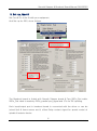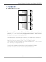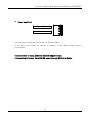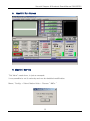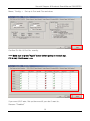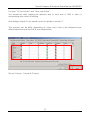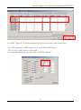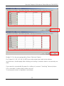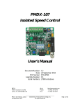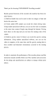
1
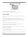
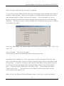
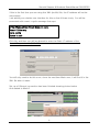
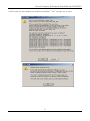
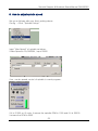
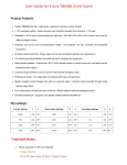
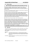
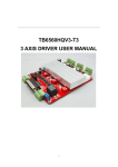
Smooth Stepper & Breakout Board Manual CM106ESS Smooth Stepper & Breakout Board for Mach3 Ethernet Smooth Stepper Feature The 11-position green screw terminals that are on the USB SmoothStepper were replaced with a 3rd parallel port. It is identical to Port 2 of the SmoothStepper, which is a "bidirectional" port. The Ethernet SmoothStepper therefore has the following I/O possibilities: Port 1: 12 Outputs and 5 Inputs Port 2: 12 Outputs and 5 Inputs OR 4 Outputs and 13 Inputs Port 3: 12 Outputs and 5 Inputs OR 4 Outputs and 13 Inputs The maximum number of Outputs is 12 + 12 + 12 = 36. In that configuration there would be 5 + 5 + 5 = 15 Inputs. The minimum number of Outputs is 12 + 4 + 4 = 20. would be 5 + 13 + 13 = 31 Inputs. In that configuration there The other possibility is 12 + 12 + 4 = 28 Outputs, and 5 + 5 + 13 = 23 Inputs. 1.Install a “Plug-in” Open the zip file and double-click the m3p file. It should copy it to the c:\Mach3\Plugins folder and rename it with a dll extension. 1 JI Robotics Smooth Stepper & Breakout Board Manual CM106ESS Run the “ESS_v10a.m3p”in the folder unzipped. This file will be disappeared automatically while installing ESS, Plug-in 2. Set-up, “Ethernet” Here are the instructions for configuring your computer's Ethernet port and running the plugin. 1. The computer's Ethernet port needs to be configured with a static IP address. Usually Ethernet ports are set up for DHCP, which allows a cable or DSL router to assign a unique address to a device that is requesting an address for the local network. Scroll down to the operating system you are using. When you get to the part where you click the radio button that says "Use the following IP address", please type in the following: IP address: 10.9.9.8 (or anything in the 10.9.9.x range, but not 10.9.9.9 because that is the address of the board) Subnet mask: 255.255.255.0 By default it will show a Subnet mask of 255.0.0.0 after you type in 10.9.9.8 be changed to 255.255.255.0. It must The Default Gateway may be left blank, as well as the Preferred and Alternate DNS servers. 2 JI Robotics Smooth Stepper & Breakout Board Manual CM106ESS That is all you need to do for the static IP address. 2. You can try running Mach at this point, but you might need to disable the firewall if it doesn't communicate. When you run Mach, a firewall warning might pop up that says an application is trying to access the Internet. Give it permission to do so. I believe it needs to be valid for Public networks and not just Home or work (private) networks. That way you won't need to disable the Firewall because you are creating an exception for Mach. If you run “Mach3Mill” the window above will show up and choose “ESS-v10a” and click “OK” If you checked, ”Don’t ask me again” It means that it will do automatically without asking next time. Depending upon whether or not the user has previously checked off the box that says "Don't ask me again" when you select a motion control device, you might need to reset that. In order to do that you will need to have Mach running (which means you will need to be pretending to be running another device such as the parallel port). Choose the pull-down menu "Function Cfg's". Then choose the option "Reset Device Sel...". The next time you run Mach it will ask you which motion control device you want to run. When you run the Ethernet SmoothStepper plugin, it will try to contact the board. 3 JI Robotics Smooth Stepper & Breakout Board Manual CM106ESS If this is the first time you are using this XML (profile) file, the IP address will not be set properly. I am working on a better user interface for this so that it flows nicely. You will be presented with a semi-cryptic message that says: CTftp::WakeupClient Board does not reply. Select YES to retry No to config Cancel to quit Click No, and then you will be allowed to enter the Static IP address of the SmoothStepper board (10.9.9.9). You will only need to do this once, since the next time Mach runs, it will find it in the XML file when it starts. Set-up of Ethernet connection has been finished showing picture below And started to Mach3 4 JI Robotics Smooth Stepper & Breakout Board Manual CM106ESS It will come out the window as follows and select “Yes” and go on to next. 5 JI Robotics Smooth Stepper & Breakout Board Manual CM106ESS 3. Set-up, Mach3 Set Port & Pin to be fit with your equipment. And Set-up for ESS, do as follows. The Breakout board is linked with Smooth Stepper board & Two_26Pin_Flat cable. 26Pin_Flat cable is made by 25Pin_parallel port_signal and 1Pin for 5V inputting. Each input/output port in breakout board is connected with the driver or can be joined limit & home sensor and it offers Relay contact signal for speed control of spindle & exterior device. 6 JI Robotics Smooth Stepper & Breakout Board Manual CM106ESS Unit mm +24V DC Power P1.1 NO Contact GND P1.17 NO Contact P1.16 NO Contact P2.17 NO Contact Spindle Speed DC Voltage Select 0~10V/0~5V P2.16 NO Contact P2.14 NO Contact P1.14 NO Contact P2.1 Spindle Speed DC Voltage Output P1.2 X axis Pulse +24V DC Power P1.15 Input P2.15 Input GND P1.3 X axis DIR P1.4 Y axis Pulse +24V DC Power P1.10 Input P1.11 Input P1.12 Input P1.13 Input GND P1.5 Y axis DIR P1.6 Z axis Pulse P1.7 Z axis DIR +24V DC Power P2.10 Input P2.11 Input P2.12 Input P2.13 Input GND P1.8 A axis Pulse P1.9 A axis DIR P2.2 B axis Pulse VOC DC Power P2.6 OC Output P2.7 OC Output P2.8 OC Output P2.9 OC Output GND P2.3 B axis DIR P2.4 C axis Pulse VOC Power Select P2.5 C axis DIR 7 JI Robotics Smooth Stepper & Breakout Board Manual CM106ESS 4. Detailed function Switch or Sensor Input Port. +24V DC Power P1.15 Input P2.15 Input GND +24V DC Power P1.10 Input P1.11 Input P1.12 Input P1.13 Input GND +24V DC Power P2.10 Input P2.11 Input P2.12 Input P2.13 Input GND There are total 10 connectors (5 for port1 / 5 for port2) as above picture, It has each 4 or 6 pins. 24V Pin here provides power of exterior sensor and can be joined to the sensor to be input by +24V If the sensor is the contact by type of switch, you can do not to use 24V Pin. Input signal here can connect “High” “Low” & “Switch Contact” The operation for each inputting can modify setting in port & pins in menu after checking it in Diagnostics(Alt-7) It can link with emergency stop button to halt the system in this port when the emergency and can connect other input button too. 8 JI Robotics Smooth Stepper & Breakout Board Manual CM106ESS Speed Control of spindle & Relay Port for controlling exterior device. P1.1 NO Contact P1.17 NO Contact P1.16 NO Contact P2.17 NO Contact P1.14 NO Contact P2.16 NO Contact P2.1 Spindle Speed DC Voltage Output P2.14 NO Contact This port outputs 0~5V or 0~10V DC voltage for speed control of spindle. In Mach3, it is outputted after the PWM signal is converted to DC voltage when speed control of spindle by PWM mode. For DC voltage can change speed of motor by connecting to servo driver or inverter. You use No. 1 Pin in Port2 Spindle Speed DC Voltage Select 0~10V/0~5V The output voltage is selected 0~5V or 0~10V range. Relay Port is comprised of COM & NO. “NO” is normal open so, it is open usually and if the relay works, it means that it is connected. No.1, 14, 16, 17 in Port 1 and No.14, 16, 17 in Port 2 are allocated. To extend exterior output, you should need an output control code. For an example, the 14 in Relay port P2 above is allotted by Pin No.14 in port2 and it is set Output #3. This output can use after assigning to M3, M7, or M8 but I show you another example to use making other M Code. 9 JI Robotics Smooth Stepper & Breakout Board Manual CM106ESS M code is saved in Mach3-macros-Mach3Mill. Open an note pad to create a new M code ActivateSignal(output3) Put down above and save as M12.m1s DeActivateSignal(output3) Put down above again and save as M13.m1s And if you spell M12 in MDI screen, the relay3 should be “On” If you spell M13, you can check it out that it should be “Off” MDI input window is in MDI(Alt-2) Port connecting to driver P1.2 X axis Pulse P1.3 X axis DIR This is the port to join the driver in each axis and is made by Pins above. This port can link with revolving axis as well as moving straightly in each axis and can do also speed control for by connecting to motor driver for spindle. For linking with driver, It applies +/- line driver and is the output 1pulse as DIR / PLS It is allotted 2~9 in port1 and 2~5 in port2 EX) Samsung servo 10 JI Robotics Smooth Stepper & Breakout Board Manual CM106ESS Line Driver MC3487 or AM26LS31 “DIR” & “SIGN” as direction signal are same. “PLS”, “PULS”, “CLOCK”, & “CLK” as pulse signal are same. Open Collector / Output Port VOC DC Power P2.6 OC Output P2.7 OC Output P2.8 OC Output P2.9 OC Output GND It is assigned 6,7,8,9 in Port2 and can join motor driver & can link with the relay for exterior control too. Power VOC using here can select below pins. If you connect with motor driver, use 5V and if the relay, use 24V VOC Power Select 11 JI Robotics Smooth Stepper & Breakout Board Manual CM106ESS Power Input Port +24V DC Power GND It is the port accepting +24V power for Board-driven. If you don’t use Power for driver in exterior, it has about 80mA current consumption. It doesn’t need to input power to smooth stepper board. It is providing 5V power from CM106 board through 26Pin Flat Cable. 12 JI Robotics Smooth Stepper & Breakout Board Manual CM106ESS 5. Mach3 / Run Screen 6. Mach3 / Set-Up “Set Value” made here, is just an example. It can possible to set it variously and can do detailed modification. Menu / Config → Select Native Units→ Choose “ MM’s “ 13 JI Robotics Smooth Stepper & Breakout Board Manual CM106ESS Menu / Config → Set up in Port and Pins as below. Confirm Pin No. & Port No. exactly. **** Make sure to press “Apply” button before going on to each tap. If it is not, it isn’t saved. **** If you use A,B,C axis, Set up them and if you don’t want to, Remove “Enabled” 14 JI Robotics Smooth Stepper & Breakout Board Manual CM106ESS For both “Dir Low Active” and “Step Low Active” You should set after judging the direction well in each axis in CNC in view of surroundings your driver is working. And Voltage Output Pin for speed control of spindle is set No.17 This process can be differ depending on users and it has to be followed some efforts experiencing a few trial & error experiments. Set up X Home, Y Home & Z Home. 15 JI Robotics Smooth Stepper & Breakout Board Manual CM106ESS If use A,B,C axis, set it and if it is not, remove “Enable” “Set Value” can be much different because users could do “Home” or ‘Limit” Set up “EStop Pin” as above. In “ActiveLow“ case here, should apply after checking out whether your emergency stop button is “Active Low” or “Active High” For probe, it is allotted for Tool Zero Sensor in Z axis. 16 JI Robotics Smooth Stepper & Breakout Board Manual CM106ESS For OEM Trigger #1 & #2 are assigned for Cycle Start and Feed Hold button. The 1000 inputted in OEM Trigger #1 is Cycle Start OEM Code. 1001 of #2 is OEM Code in Feed Hold. For more detailed thing, hope to refer to MACH3 manual. 17 JI Robotics Smooth Stepper & Breakout Board Manual CM106ESS Enable 2~5 is the pin assigned by Open Collector Output. For Output #1, #2, #3, #4, & #5Pin are relay output port and set as above. In ActiveLow, should apply after thinking according to exterior device connected your CNC. If you want to use spindle & pump for cutting oil, remove “checking” above picture. If it is checked, it means that it does not use. To set speed control of spindle is as follows.. 18 JI Robotics Smooth Stepper & Breakout Board Manual CM106ESS 7. Motor Tuning Menu / Config → choose “ Motor Tuning” Select “X axis” and set to be fit user’s equipment. For Velocity or Acceleration, it can alter adequately. ***** Make sure to press “Save Axis Setting” after inputting. 19 JI Robotics Smooth Stepper & Breakout Board Manual CM106ESS 20 JI Robotics Smooth Stepper & Breakout Board Manual CM106ESS 21 JI Robotics Smooth Stepper & Breakout Board Manual CM106ESS Menu / Config → Choose “Motor Homing” and set as below. For more detailed explanation as for each functions, refer to mach3 program manual. 22 JI Robotics Smooth Stepper & Breakout Board Manual CM106ESS 8. How to adjust spindle speed Set up as follows after you finish setting above. Config → Click “Spindle Pulleys” Input “Max Speed” of spindle as below. If Max Speed is 20,000RPM , input 20000 If so, can do speed control of spindle in mach program. If it is S1000 on G code, It means the spindle RPM is 1000 and if it is S5000 It means the RPM is 5000 23 JI Robotics Smooth Stepper & Breakout Board Manual CM106ESS 9. Further Information Allotted pin for Home & Limit Sensor is available in many ways. You can connect one pin together to Home & Limit sensor in each axis in CNC and the rest of pins can be allocated by switch input too after setting up Probe Sensor or OEM Trigger. For more detailed, refer to MACH3 manual. ** If you have any questions or concerns, feel free to contact us anytime via facebook below. Go to Page : http://www.facebook.com/pages/JI-Robo-Cnc/102510056566519?ref=hl Pls..First, Click “ Like” and leave a comment [email protected] 24 JI Robotics