1
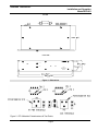
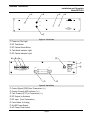
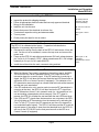
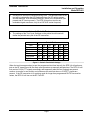
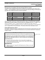
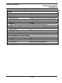
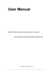
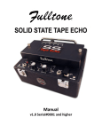
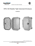
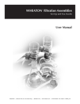
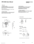
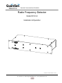
Industrial Communications Worldwide Radio Frequency Detector Model RFD-VU Installation & Operation P006772 Rev. B 070607 7/28/2014 11:53 AM 7552 - 10th Street N.E. Calgary, Alberta, Canada T2E 8W1 Ph: 403.258.3100 \ email:[email protected] \ www.guardiantelecom.com Guardian Telecom Inc. Installation and Operation Model RFD-VU Table of Contents Package Contents.................................................................................2 Overview ...............................................................................................3 Features ................................................................................................3 Installing the RFD-VU ...........................................................................6 Calibration .............................................................................................6 Manual Test ..........................................................................................6 Automatic Periodic Test ........................................................................7 Field Repairs & Adjustments.................................................................8 Engineering Specifications....................................................................9 Warranty..............................................................................................10 Disclaimer ...........................................................................................10 Warning...............................................................................................10 Service Number ..................................................................................10 Feedback ............................................................................................10 Guardian Product Return ....................................................................11 Table of Figures Figure 1 - Dimensions ...........................................................................4 Figure 2 - RF Calibration Potentiometers & Test Points .......................4 Figure 3 - Front Plate ............................................................................5 Figure 4 - Back Plate.............................................................................5 Figure 5 - Periodic Test Switch Settings ...............................................7 Package Contents (1) RFD-VU Radio Frequency Detector (1) Installation & Operation Manual Page 2 Guardian Telecom Inc. Installation and Operation Model RFD-VU Overview RFD-VU Radio Frequency Detector The RFD-VU Radio Frequency Detector monitors radio frequency output from a VHF or UHF transceiver and provides front panel & remote LED indication of RF carrier frequency failure. A timed RF test option is provided to automate the procedure to save from scheduled manual testing of RF transceiver unit. Features 16 gauge steel enclosure - zinc dichromate plated and powder coated 10 gauge steel faceplate - zinc dichromate plated and powder coated Compact 19” rack mount - two rack units (2U) Programmable auto test interval VHF/UHF frequency compatible Front mounted controls and status indicator LEDs Page 3 Guardian Telecom Inc. Installation and Operation Model RFD-VU TOP VIEW FRONT VIEW Guardian Telecom Inc. RF TEST POWER RESET TEST FAIL RFD-VU RADIO FREQUENCY DETECTOR Figure 1 - Dimensions Figure 2 - RF Calibration Potentiometers & Test Points Page 4 Guardian Telecom Inc. Installation and Operation Model RFD-VU 1 2 4 5 Guardian Telecom Inc. RF TEST POWER RESET TEST FAIL RFD-VU RADIO FREQUENCY DETECTOR 3 Figure 3 - Front Plate Power on Pilot Light RF Test Button RF Failure Reset Button Test Mode Indicator Light RF Failure Indicator Light 1 2 3 6 POWER 7 F U SE 8 F U SE ANT + - CTN CTN + - + TX FUSE 1/2 A - CC CC TST TST LED LED TX TX 220 VAC 4 Figure 4 - Back Plate Control Signal [COS] from Transceiver (+/-) Control Console LED Indicator (+/-) Test Transmit [PTT] to Transceiver (+/-) RF Output (to Antenna) RF Input (from Transceiver) Fuse Holder (0.5 Amp) On/Off Power Switch AC Power Cord Socket Page 5 5 Guardian Telecom Inc. Installation and Operation Model RFD-VU Installing the RFD-VU Inspect the product for shipping damage. Follow all appropriate electrical codes and use only approved electrical fittings for the installation. Install the unit into the rack. Ensure that none of the electrical circuits are live. Terminate all respective wiring and antenna cables. Turn on power. Check power pilot light for turn-on status. Tip: If the product is damaged, notify the carrier immediately. Tip: Two rack units are required See: Figure 4 - Back Plate Calibration The RFD-VU is calibrated at the factory. If operation indicates that recalibration is necessary adjust as follows. Disconnect the wiring from the back of the RFD-VU and remove it from the rack. Set the unit on a workbench, remove the top cover and connect the power cord. Power up the RFD-VU and adjust potentiometer R43 until voltage between pin 3 to pin 4 of U3 reads 2.0 VDC. Adjust potentiometer R11 until voltage between pin 2 to pin 4 of U1 reads 20mVDC. Install the unit back into the rack, reconnect wiring and test. Manual Test When the Manual Test switch is pressed on the unit front panel, the RFDVU will monitor the Carrier Operated Squelch (COS) input from the RF transceiver base for a receive signal. If the RF transceiver is receiving a signal, the RFD-VU will abort the test and flash the test LED three times as well as the LED on a Control Console (if equipped). This indicates a live RF transmission was occurring from remote hand held units at that moment and the test cycle was halted. If the RF transceiver is not in receive mode (no remote RF transmission is occurring at the time), the RFD-VU will then monitor the PTT signal from the RF transceiver to see if it is in transmit mode (i.e., the transceiver is in use and making a transmission at that moment). If the PTT signal is present, the RFD-VU will abort the test and flash the test LED three times. If the COS and PTT signals from the transceiver are not present, the RFDVU will initialize an RF transmission from the transceiver by activating the Push To Talk (PTT) input to the RF transceiver and force it to transmit (a non-modulated carrier signal). The RFD-VU will then read the RF meter for transmit power. If the power is lower than the threshold level, the RFD-VU will turn on the RF-Fail LED on the front panel as well as the LED on a Control Console (if equipped). Page 6 See: Figure 2 - RF Calibration Potentiometers & Test Points Guardian Telecom Inc. Installation and Operation Model RFD-VU A manual RF test can be conducted at any time. The failure/success of the test will be indicated by the LED flashing 3 times (for RF activity present and test aborted), LED illuminated solid (RF failure) of no illumination (test passed and RF carrier present). The RFD-VU does not test for any modulated signal waveforms, only for a VHF/UHF carrier frequency. Automatic Periodic Test The settings of the Test Cycle Switches on the printed circuit board will define the periodic test cycle of the RF transceiver. Time One minute 10 minutes 30 minutes 60 minutes Four hours Eight hours #1 On Off Off Off Off Off #2 Off On Off Off Off Off Switch Positions #3 #4 #5 Off Off Off Off Off Off On Off Off Off On Off Off Off On Off Off Off #6 Off Off Off Off Off On Figure 5 - Periodic Test Switch Settings When the test time approaches (as per the programmed test time interval), the RFD-VU will perform a test on the RF transceiver with the exact same procedure as manually activated test. The RFD-VU will first monitor COS & PTT signals accordingly and temporarily abort the test if signals are present, continue to monitor for non-activity and commence the auto test when no COS/PTT signals are present. If the RF transceiver is in receiving mode for longer than programmed RX/TX time monitor values, the RFD-VU will turn on the RF Fail LED. Page 7 Guardian Telecom Inc. Installation and Operation Model RFD-VU RF transceiver transmitting (TX) and receiving (RX) time monitor The RFD-VU will constantly monitor the RF transceiver for transmitting and receiving time duration. If the transmitting or receiving time is longer than the time settings in DIP switch #7 and switch #8, the RFD-VU will turn on the RF Fail LED. Switches #7 #7 OFF position X Switches #8 #8 OFF position X ON position X ON position X COS Timer Value 2 minutes 10 minutes PTT Timer Value 2 minutes 10 minutes If the COS signal is present for longer then the timer values, RF transmission is possibly maintained too long as a result of a switch failure on a handheld radio unit. The failure LED will then illuminate. If the PTT signal is present for longer then the timer values, RF transmission is possibly maintained too long as a result of a switch failure on the transceiver unit or a radical failure of the transceiver. The failure LED will then illuminate as well. Clearing RF transceiver failure Once the RF transceiver failure is registered the RF Fail LED will be cleared when the Clear Fail Switch is pressed. Or another RF transceiver test is performed with the RF transceiver problem is fixed. Field Repairs & Adjustments Field repairs and adjustments may only be carried out by qualified technicians. This device has no user serviceable internal components; The only adjustments are calibration potentiometer settings on the main PCB. The only maintenance possible is the replacement of the fuse – which is available from the back panel. Fuse Replacement Remove the old fuse by pushing in the end cap of the fuse holder and turning counterclockwise to open. Insert a new 0.5 amp, 250Volt, 3AG fast blow fuse and close the fuse holder. WARNING! Replace only with a 0.5 amp 250V 3AG fast blow fuse. Failure to do so will void the warranty. Page 8 See: Figure 4 - Back Plate Guardian Telecom Inc. Installation and Operation Model RFD-VU Engineering Specifications Electrical POWER SUPPLY 230 VAC FUSE ½ AMP; 250 VOLT; 3AG RF Input/Output FREQUENCY RANGE RANGE140-170 / 430-450MHZ (VHF/UHF DUAL BAND) POWER RANGE 0-60 WATTS INSERTION LOSS LESS THAN 0.3 dB IMPEDANCE 50 OHMS NOTE: THE RF INPUT AND RF OUTPUT SECTIONS ARE NOT INTERCHANGEABLE Input/Output Control signals TST TX LOGIC INPUT OPTO RELAY ISOLATED, 5mA@12VDC MAX. CNT LOGIC INPUT 3V CC LED LED DRIVING OUTPUT Test Cycle Timer Setting EIGHT POSITION DIP SWITCH SETTING RANGING FROM ONE MINUTE TO EIGHT HOURS Front Panel Displays and Control Switches POWER ON LED POWER ON DISPLAY TEST LED RF TRANSMITTER UNDER TEST DISPLAY FAIL LED RF TRANSMITTER FAIL DISPLAY RF TEST SWITCH MANUAL TEST TRIGGERING SWITCH RESET SWITCH RESET THE LAST FAIL EVENT SWITCH Page 9 Guardian Telecom Inc. Installation and Operation Model RFD-VU Warranty Guardian Telecom warrants your product to be free of defects in material and workmanship for a period of one year. Guardian Telecom will repair or replace any defective unit that is under warranty free of charge. This warranty is null and void if any non-authorized modifications have been made to this product, or if it has been subjected to misuse, neglect, or accident. This warranty covers bench repairs only; such repairs must be made at Guardian Telecom or an authorized service depot. Guardian Telecom is not responsible for costs incurred for on-site service calls, freight, or brokerage. A return authorization must be obtained prior to warranty claims or repairs. Disclaimer The products covered by this manual are designed for use in Industrial Environments and/or Hazardous Locations. Due to the range of possible applications for these instruments the manufacturer will not be responsible for damages or losses of any kind suffered as a result of the use of this product, including consequential damages. Warning This device has no user serviceable internal components; The only adjustment is a calibration potentiometer setting on the main PCB. The only maintenance possible is the replacement of the fuse – which is available from the back panel. Service Number 1-800-363-8010 Guardian Telecom provides a customer service number which is toll-free within North America. If you need assistance when installing or operating this product, please call the toll-free number between regular business hours (8:00AM-5:00PM), Mountain Standard Time. If you are calling outside of regular business hours, please leave a detailed message and a member of Guardian Telecom’s Service Department will return your call as soon as possible. If your product requires service, Guardian personnel will supply you with an RMA (return materials authorization) number over the telephone or through our web site product return page. This number must be included with your return address and the name of the person to contact. Guardian Telecom Inc. 7552 - 10th Street N.E. Calgary, Alberta, Canada T2E 8W1 Toll-free 1-800-363-8010 Ph. (403) 258-3100 Fax. (403) 253-4967 www.guardiantelecom.com Feedback Guardian Telecom continually strives to make reliable, durable, and easy to use products. If you, as an installer or user of our equipment, have any suggestions for improvements to this or any of our products or documents, including this manual, we would appreciate hearing from you. Page 10 Guardian Telecom Inc. Installation and Operation Model RFD-VU Guardian Product Return Guardian products have been quality tested and are in full working order when shipped from the factory, given the rugged nature of these products shipping is not expected to damage a unit. In the unlikely event of a malfunction, Guardian follows the three step procedure below. Step I - On-Site Correction The most common source of difficulties with a new product is improper installation in one of two ways: incorrect wiring connections or connection to an incorrect power source. Product wiring needs to be properly connected to the on-site wiring. Correct wiring instructions are shown in the user manual included with the product. Connecting a to a standard power source, rather than tip & ring, will blow the ’s internal, user-replaceable fuse. In the event of fuse burn-out, disconnect the from the power source, replace the fuse, and reconnect following the wiring diagrams provided with the product. Step II - Return Materials Authorization (RMA) When a product has been installed following user manual instructions, and the unit fails to operate, the user must contact Guardian Telecom to obtain authorization to return the product. This can be done by completing a RMA form online at www.guardiantelecom.com, or by calling the service number given in this manual. After providing information on the product, the owner and the nature of the problem, Guardian will issue a RMA number, to be shown on documentation returned with the product. In addition to the RMA number, shipping documents should include name, address and number of the owner along with contact information for the person responsible for the repair and/or the user who identified the malfunction. (Where a product is being returned for repair from outside of Canada, customs documentation must show the product’s serial number, date of export [date of purchase], and a notation that the equipment is: “Canadian goods returning”. Step III - Factory Authorized Service Once received, each product is carefully inspected and tested. If the product is under warranty, repairs are completed and the product returned to the owner, generally within five working days of receipt by the factory. A product that has been subjected to misuse, neglect or accident or is beyond the warranty period will be evaluated. The service department will provide the owner’s representative with a repair cost estimate. Once approved, repairs are completed and the product returned, generally within five working days. Page 11 Guardian Telecom Inc. 7552 - 10th Street N.E. Calgary, Alberta, Canada T2E 8W1 Toll-free 1-800-363-8010 Ph. (403) 258-3100 Fax. (403) 253-4967 www.guardiantelecom.com E-mail: mailto:[email protected] (Click to open message box) Industrial Communications Worldwide © Guardian Telecom Inc. 2007