1
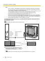
Quick Installation Guide
DECT Cell Station Unit
Model No.
KX-TDA0141
KX-TDA0142
KX-TDA0155
KX-TDA0156
KX-TDA0158
Thank you for purchasing a Panasonic DECT Cell Station Unit.
Please read this manual carefully before using this product and save this manual for future use.
Important Information
Important Information
SAVE THESE INSTRUCTIONS
Safety Notices
Please observe the safety notices in this manual in order to avoid danger to users or other people, and prevent
damage to property.
The notices are classified as follows, according to the severity of injury or damage:
WARNING
This notice means that misuse could result in death or serious injury.
CAUTION
This notice means that misuse could result in injury or damage to
property.
WARNING
SAFETY REQUIREMENTS
• The product must only be installed and serviced by qualified service personnel. The product should be
used as-is from the time of purchase; it should not be disassembled or modified. Disassembly or
modification can cause a fire, electric shock, or damage to the product.
• Make sure that the wall that the unit will be attached to is strong enough to support the unit (approx.
310 g). If not, it is necessary for the wall to be reinforced.
• Only use the wall-mounting equipment (screws, washers) included with the unit.
• When this product is no longer in use, make sure to detach it from the wall.
• Do not connect or disconnect the telephone cord with wet hands.
• Disconnect the unit from the telephone cord, and contact the dealer if:
– The unit is exposed to rain, water, or any other liquid.
– The unit is dropped or damaged.
– Internal components are exposed due to damage.
– The unit does not operate properly.
– Performance deteriorates.
• Disconnect the unit from the telephone cord if the unit emits smoke, an abnormal smell, or makes
unusual noise. These conditions can cause fire or electric shock. Confirm that smoke has stopped and
contact an authorised service centre.
• Do not touch the unit, or telephone cord during a lightning storm.
• Do not allow anything to rest on the telephone cord. Do not locate this unit where the telephone cord
may be stepped on or tripped on.
CAUTION
SAFETY REQUIREMENTS
• The CS should be kept free of dust, moisture, high temperature (more than 40 °C), low temperature
(less than 0 °C), and vibration, and should not be exposed to direct sunlight.
• The CS should not be placed outdoors (use indoors).
• The CS should not be placed near high-voltage equipment.
• The CS should not be placed on a metal object.
• When driving the screws into the wall, be careful to avoid touching any metal laths, wire laths or metal
plates in the wall.
• To prevent malfunction, deformity, overheating, rust, and discolouration, do not install or place
equipment in the following types of locations:
2
Quick Installation Guide
Important Information
–
–
–
–
–
•
•
•
•
•
•
•
•
Locations where air ventilation is poor.
Locations that may be exposed to sulphurous gas, such as near hot springs.
Near devices that emit heat, such as heaters.
Near devices that emit electromagnetic noise, such as radios or televisions.
Near devices that emit high-frequency noise, such as sewing machines or welders.
Do not stretch or bend the cables. Also, do not allow anything to rest on the cables.
Use cables that are fire-resistant or fireproof.
The CS and the cables should never be placed near or over a radiator or other heat source.
Do not bundle cables that are connected to the CS with the AC power cords of machines located
nearby.
Make sure the cables are securely fastened to the wall.
Disconnect the telephone cord from the unit before cleaning. Clean the unit with a soft, dry cloth. Do
not use liquid, aerosol cleaners, abrasive powders, or chemical agents to clean the unit.
When left unused for a long period of time, disconnect the unit from the telephone cord.
Medical—consult the manufacturer of any personal medical devices, such as pacemakers, to
determine if they are adequately shielded from external RF (radio frequency) energy. (The unit operates
in the frequency range of 1880 MHz to 1900 MHz, and the output peak power level is less than
0.25 W.) Do not use the unit in health care facilities if any regulations posted in the area instruct you
not to do so. Hospitals or health care facilities may be using equipment that could be sensitive to
external RF (radio frequency) energy.
Notice
SAFETY REQUIREMENTS
• Before connecting the unit, confirm that the unit supports the intended operating environment.
• If the unit does not operate properly, disconnect the telephone cord, then connect again.
• The unit may not operate in the event of a power failure.
• Do not move the unit while it is in use.
• Satisfactory operation, interoperability, and compatibility cannot be guaranteed with all equipment
connected to the unit, nor with all services provided by telecommunications providers over networks
connected to the unit.
SECURITY REQUIREMENTS
• Privacy of communications may not be ensured when using the wireless systems.
Note
In this manual, the suffix of each model number (e.g., KX-TDA0141CE) is omitted unless necessary.
Quick Installation Guide
3
Important Information
Additional Information
For users in the European Union only
Information for Users on Collection and Disposal of Old Equipment and used Batteries
These symbols on the products, packaging, and/or accompanying documents mean that
used electrical and electronic products and batteries should not be mixed with general
household waste.
For proper treatment, recovery and recycling of old products and used batteries, please take
them to applicable collection points, in accordance with your national legislation and the
Directives 2002/96/EC and 2006/66/EC.
By disposing of these products and batteries correctly, you will help to save valuable
resources and prevent any potential negative effects on human health and the environment
which could otherwise arise from inappropriate waste handling.
For more information about collection and recycling of old products and batteries, please
contact your local municipality, your waste disposal service or the point of sale where you
purchased the items.
Penalties may be applicable for incorrect disposal of this waste, in accordance with national
legislation.
For business users in the European Union
If you wish to discard electrical and electronic equipment, please contact your dealer or
supplier for further information.
Information on Disposal in other Countries outside the European Union
These symbols are only valid in the European Union. If you wish to discard these items,
please contact your local authorities or dealer and ask for the correct method of disposal.
Note for the battery symbol (bottom two symbol examples):
This symbol might be used in combination with a chemical symbol. In this case it complies
with the requirement set by the Directive for the chemical involved.
4
Quick Installation Guide
Table of Contents
Table of Contents
1
2
3
4
5
6
7
8
9
Overview ...................................................................................................6
Procedure Overview ..............................................................................11
Site Planning ..........................................................................................13
Before Site Survey .................................................................................17
Site Survey Using the KX-TCA175/KX-TCA255/KX-TCA256/
KX-TCA275/KX-TCA355/KX-TD7590 .....................................................25
After Site Survey ....................................................................................29
Connecting a Cell Station to the PBX ..................................................30
Wall Mounting .........................................................................................55
Troubleshooting .....................................................................................60
Quick Installation Guide
5
1 Overview
1 Overview
Names and Locations
KX-TDA0155/KX-TDA0156
Antennas
CS ID Number
(ID: xxxxxxxxxx)
RJ11 Modular
LED
DIP Switch
KX-TDA0158
Antennas
CS ID Number
(ID: xxxxxxxxxx)
DIP Switch
RJ45 Modular
LED
KX-TDA0141/KX-TDA0142
Antennas
CS ID Number
(ID: xxxxxxxxxx)
RJ11 Modular
DIP Switch
6
Quick Installation Guide
1 Overview
LED Indications (KX-TDA0155/KX-TDA0156/KX-TDA0158)
Indication
STATUS
Colour
Green/Red
Description
CS status indication
OFF: Power Off
Green ON: Stand-by (no active calls)
Slow Green Flashing (60 times per minute): Talk (active calls)
Moderate Green Flashing (120 times per minute): Busy
Red ON: Fault (includes Initialisation)
Red Flashing (60 times per minute): Out of Service/Starting up
•
•
•
•
•
•
CS status indication during the site survey
• Red ON: The CS is connected to an AC adaptor/battery box.
• Red Flashing (60 times per minute): The CS is connected to the
PBX.
Compatible PBX
PBX
Cell Station
Model No.
KX-TDA0155/
KX-TDA0141
KX-TDA15
PSMPR Software File Version 1.1000 or later
KX-TDA30
PSMPR Software File Version 1.0000 or later
KX-TDA100
KX-TDA200
KX-TDA600
KX-TDE100
KX-TDE200
KX-TDE600
KX-NCP500
KX-NCP1000
KX-TDA0156/
KX-TDA0142
MPR Software Version
KX-TDA100
KX-TDA200
KX-TDA600
KX-TDE100
KX-TDE200
KX-TDE600
PMPR Software File Version 1.1000 or later
PLMPR Software File Version 2.2000 or later
PMMPR Software File Version 1.0000 or later
PGMPR Software File Version 2.0000 or later
PBMPR Software File Version 1.0000 or later
PMPR Software File Version 1.0000 or later
PLMPR Software File Version 2.2000 or later
PMMPR Software File Version 1.0000 or later
PGMPR Software File Version 2.0000 or later
Quick Installation Guide
7
1 Overview
PBX
Cell Station
Model No.
KX-TDA0158
MPR Software Version
KX-TDA15
PSMPR Software File Version 5.0000 or later
KX-TDA30
PSMPR Software File Version 5.0000 or later
KX-TDA100
KX-TDA200
KX-TDA600
KX-TDE100
KX-TDE200
KX-TDE600
KX-NCP500
KX-NCP1000
PMPR Software File Version 5.0000 or later
PLMPR Software File Version 5.0000 or later
PMMPR Software File Version 1.0000 or later
PGMPR Software File Version 2.0000 or later
PBMPR Software File Version 1.0000 or later
Maximum Number of Calls
Cell Stations (CSs) determine the area covered by the wireless system. The number of calls that can be made
simultaneously through each CS varies depending on the model, as follows:
Cell Station
Maximum Calls
KX-TDA0155
2
KX-TDA0156
4
KX-TDA0158
8
KX-TDA0141
2
KX-TDA0142
4
Compatible Portable Station
•
•
•
•
•
•
•
•
KX-TCA155
KX-TCA175
KX-TCA255
KX-TCA256
KX-TCA275
KX-TCA355
KX-TD7590
KX-TD7580
Note
For more details about the Portable Station (PS), refer to the Operating Instructions of the PS.
Maximum Number of CSs Supported by PBX
Notice
The CSs are for connection to specified Panasonic PBXs only.
The following number of CSs can be supported by each PBX.
8
Quick Installation Guide
1 Overview
Maximum Number
PBX
Connected via
KX-TDA0158
KX-TDA0155/
KX-TDA0141
KX-TDA0156/
KX-TDA0142
Super Hybrid
Ports
DLC card
2
4
-
4
8
-
•
Super Hybrid
Ports
DLC card
•
•
DHLC card
DLC card
16
32
-
•
CSIF card
-
-
32
•
•
DHLC card
DLC card
64
128
-
•
CSIF card
-
-
128
•
•
DHLC card
DLC card
16
32
-
•
CSIF card
-
-
32
•
•
DHLC card
DLC card
64
128
-
•
CSIF card
-
-
128
KX-NCP500
•
•
DHLC card
DLC card
2
4
-
KX-NCP1000
•
•
DHLC card
DLC card
4
8
-
KX-TDA15
•
•
KX-TDA30
(with Additional AC
Adaptor)
KX-TDA100/
KX-TDA200
KX-TDA600
KX-TDE100/
KX-TDE200
KX-TDE600
•
Required Distances between Equipment
CAUTION
Maintain the distances listed below between equipment in order to prevent noise, interference or the
disconnection of a conversation. (The distance may vary depending on the environment.)
Equipment
Distance
CS and office equipment such as a computer, telex, fax
machine, etc.
More than 2 m
CS and PS
More than 1 m
Each CS
More than 3 m
Each PS
More than 0.5 m
PBX and CS
More than 2 m
Quick Installation Guide
9
1 Overview
Notice
If multiple CSs cover the same area, the phone connection may become noisy or the number of possible
simultaneous calls with PSs may decrease due to interference between the CSs. For details, refer
to "5 Site Survey Using the KX-TCA175/KX-TCA255/KX-TCA256/KX-TCA275/KX-TCA355/KX-TD7590
—Testing the Radio Signal Strength".
The required distance between CSs may vary depending on the environment of the installation site and
conditions in which the wireless system is used. Conduct a site survey to determine the appropriate
distance.
RF Specification
Item
Description
Radio Access Method
MultiCarrier TDMA-TDD
Frequency Band
1880 MHz to 1900 MHz*1
Number of Carriers
10*2
Carrier Spacing
1728 kHz
Bit Rate
1152 kbps
Carrier Multiplex
TDMA, 24 (Tx12, Rx12) slots per frame
Frame Length
10 ms
Modulation Scheme
GFSK
Roll-off factor=0.5
*1
*2
50 % roll-off in the transmitter
Data Coding for Modulator
Differential Coding
Voice Codec
32 kbps ADPCM (CCITT G.721)
Transmission Output
Peak 250 mW
If the suffix of your PBX model is BX, TW, or XE, the value is 1880 MHz to 1895 MHz.
If the suffix of your PBX model is BX, TW, or XE, the value is 8.
CAUTION
•
•
•
•
•
10
The CS should be kept free of dust, moisture, high temperature (more than 40 °C), low temperature
(less than 0 °C), and vibration, and should not be exposed to direct sunlight.
The CS should not be placed outdoors (use indoors).
The CS should not be placed near high-voltage equipment.
The CS should not be placed on a metal object.
Do not use this wireless system near another high-power cordless system such as DECT or SS
wireless.
Quick Installation Guide
2 Procedure Overview
2 Procedure Overview
When connecting the wireless system, use extreme care in conducting the site survey. Site surveys can be
conducted using the KX-TCA175/KX-TCA255/KX-TCA256/KX-TCA275/KX-TCA355/KX-TD7590 PS. An
incorrectly performed site survey can result in poor service area, frequent noise, and disconnection of calls.
1. Investigate the installation site
Refer to "3 Site Planning".
a. Obtain a map of the CS installation site.
b. Identify the service area required by the user on the map.
c. Plan the location of each CS, taking account of distance, building materials, etc.
2. Prepare for site survey
Refer to "4 Before Site Survey".
a. Check and assign the CS ID number to the PS.
b. Assign a channel number to each CS by setting the DIP switches on the back of the CS.
c. Supply electricity to each CS using an AC adaptor/battery box or by connecting them to the PBX.
d. Install each CS temporarily as planned.
Note
•
•
Install at least 2 m above the floor.
Place the antennas so that they are pointing in directions that are 90 degrees apart (for antenna
diversity).
3. Conduct the site survey
Refer to "5 Site Survey Using the KX-TCA175/KX-TCA255/KX-TCA256/KX-TCA275/KX-TCA355/
KX-TD7590".
a. Test the radio signal strength using the PS.
Confirm that the radio signal strength level is "12" near the CS.
Using the KX-TCA175/KX-TCA255/KX-TCA256/KX-TCA275/KX-TCA355
To survey
specific channel
1
9
0
Press 1, 9, and POWER
for more than 2 seconds.
Channel No.
Display example:
RADIO STRENGTH
<<< MEASURING >>>
0 to 9
RADIO STRENGTH
CH0 SLOT:06 SYNC
L:12 0000/0100
CS-ID:9005301234
Using the KX-TD7590
To survey
specific channel
1
9
Press 1, 9, and POWER
for more than 5 seconds.
0
Channel No.
0 to 9
Display example:
RADIO STRENGTH
<<< MEASURING >>>
CH0 SLOT:06 SYNC
L:12 0000/0100
CS-ID:9005301234
b. By walking away from the CS with the PS, check the radio signal strength. The radio signal strength
weakens as you walk away from the CS.
Quick Installation Guide
11
2 Procedure Overview
c. Map the CS coverage area at radio signal strength levels "3" and "8".
d. Make sure that adjacent CS coverage areas overlap where the radio signal strength level is "8" by at least
5 m.
e. Make sure that the radio signal strength level is greater than "3" at any location within the service area
required by the user.
4. Finish the site survey
Refer to "6 After Site Survey".
a. Turn off the PS.
b. Stop supplying power, and return all DIP switches of each CS to the OFF position.
5. Connect the CS and PS to the PBX and test the operation
Refer to "7 Connecting a Cell Station to the PBX".
a. Connect the CSs to the PBX.
b. Register the PSs to the PBX.
c. Walk around the service area while having a conversation using a registered PS. If noise is frequent or
conversations disconnect, relocate the CSs or install an additional CS.
6. Mount the CS on the wall
Refer to "8 Wall Mounting".
a. If there are no problems in testing, mount the CS on the wall.
12
Quick Installation Guide
3 Site Planning
3 Site Planning
Choosing the best site for the CS requires careful planning and testing of essential areas. The best location
may not always be convenient for installation. Read the following information before installing the unit.
Understanding Radio Waves
Characteristics of Radio Waves
The transmission of radio waves and the CS coverage area depend on the structure and materials of the
building.
Office equipment, such as computers and fax machines, can interfere with radio waves. Such equipment may
create noise or interfere with the performance of the PS.
The illustration below shows the special transmitting patterns of radio waves.
1. Radio waves are reflected by objects made of materials such as metal.
2. Radio waves are diffracted by objects such as metallic columns.
3. Radio waves penetrate objects made of materials such as glass.
CS
1. Reflection
Column
2. Diffraction
3. Penetration
Relationships between Radio Waves and Building Structure and Materials
• The CS coverage area is affected more by the building materials and their thickness than the number of
•
•
•
•
obstacles.
Radio waves tend to be reflected or diffracted by conductive objects and rarely penetrate them.
Radio waves tend to penetrate insulated objects and are rarely reflected by them.
Radio waves penetrate thin objects more than thick objects.
The table below shows the transmission tendency of radio waves when they reach objects made from
various materials.
Quick Installation Guide
13
3 Site Planning
Object
Wall
Transmission Tendency
Concrete
The thicker they are, the less radio waves penetrate
them.
Ferroconcrete
Radio waves can penetrate them, but the more iron
there is, the more radio waves are reflected.
Glass
Radio waves usually penetrate them.
Glass with wire net
Radio waves can penetrate them, but tend to be
reflected.
Glass covered with
heat-resistant film
Radio waves are weakened considerably when they
penetrate windows.
Floor
Ferroconcrete
Radio waves can penetrate them, but the more iron
there is, the more radio waves are reflected.
Partition
Steel
Radio waves are reflected and rarely penetrate them.
Plywood, Glass
Radio waves usually penetrate them.
Ferroconcrete
Radio waves can penetrate them, but the more iron
there is, the more radio waves tend to be reflected or
diffracted.
Metal
Radio waves tend to be reflected or diffracted.
Steel
Radio waves are usually reflected or diffracted, and
rarely penetrate them.
Wood
Radio waves can penetrate them, but they are
weakened.
Window
Column
Cabinet
14
Material
Quick Installation Guide
3 Site Planning
CS Coverage Area
The example below shows the size of the coverage area of 1 CS if it is installed in an area with no obstacles.
Note
Radio signal strength levels are measured during the site survey (refer to "5 Site Survey Using the
KX-TCA175/KX-TCA255/KX-TCA256/KX-TCA275/KX-TCA355/KX-TD7590").
A
Coverage Area
Radio signal strength level is
greater than "3".
(About 50 m to 60 m)
A
B
Gray Zone:
Conversation will be
intermittent
B
C
Good Coverage Area
Radio signal strength
level is greater than "8".
(About 30 m to 40 m)
Good sound quality
can be maintained.
Out of Service:
Cannot make/receive calls
Radio Signal Strength Levels
Level: 11 to 12
Level: 08 to 10
Level: 03 to 07
Level: 01 to 02
Level: 00
Better
Good
May receive noise
Receives noise easily or disconnects
Out of range
Site Survey Preparation
1. Obtain a map and investigate the installation site.
a. Check the obstacles (e.g., shelves, columns, and partitions).
b. Check the materials of the structures (e.g., metal, concrete, and plywood).
c. Check the layout and dimensions of the room, corridor, etc.
d. Write down the above information on the map.
2. Examine the service area required by the user on the map, referring to the following example.
a. Draw the coverage area around a CS. Extend the coverage area 30 m to 60 m in each direction,
depending on the materials of the building structures and obstacles in the installation site. Note that a
CS cannot be installed outside a building.
Quick Installation Guide
15
3 Site Planning
b. If 1 CS cannot cover the entire service area, install additional CSs as required. Overlap the coverage
areas of adjacent CSs.
Where CS coverage areas overlap, the PS will start call handover to the next CS if the signal from one
CS becomes weak. However, if a PS moves away from a CS and there are no CSs available for
handover, the PS may go out of range and the call could be lost.
Example: Installing in a Room Separated by Interior Walls
Things to take note of:
• The room is separated by interior walls.
• The room is surrounded by concrete walls.
CS installation plan:
• The coverage area of each CS will not extend as far as when there are no obstacles, because the radio
signals will be weakened by separating walls. Therefore, you will need 5 CSs to cover the entire room.
150 m
70 m
CS no. 1
CS no. 2
CS no. 5
CS no. 3
16
Quick Installation Guide
CS no. 4
4 Before Site Survey
4 Before Site Survey
Use the KX-TCA175/KX-TCA255/KX-TCA256/KX-TCA275/KX-TCA355/KX-TD7590 PS to conduct the site
survey.
Note
Display prompts for the site survey are only available in English.
Checking the CS ID Number
Check the CS ID number label attached to the CS. If the CS ID number label is not attached to the CS, check
the CS ID number using the Maintenance Console. For details, refer to "Utility—CS Information" in the PC
Programming Manual or the On-line Help for your PBX.
Assigning the CS ID Number to the PS
Using the KX-TCA175/KX-TCA255/KX-TCA256/KX-TCA275/KX-TCA355
To enter letters
9
1
ABC
2
Press 1, 9, and POWER
for more than 2 seconds.
A:
+
0
C:
+
ABC
2
E:
+
GHI
4
B:
+
1
D:
+
DEF
3
F:
+
JKL
5
CS No.
CS ID No.
0 to 7
0 to 9 and A to F
To the Desired CS No.
To the initial display
Note
To clear the CS ID number assigned to the PS, follow the procedure below:
To clear one by one
CS No.
0 to 7
1
9
DEF
3
To the Desired CS No.
Press 1, 9, and POWER
for more than 2 seconds.
OR
To clear all at once
To the initial display
#
Quick Installation Guide
17
4 Before Site Survey
Using the KX-TD7590
To enter letters
9
1
ABC
2
Press 1, 9, and POWER
for more than 5 seconds.
A:
F1
C:
F3
E:
B:
F2
D:
INT'
F:
CS No.
CS ID No.
0 to 7
0 to 9 and A to F
OK
To the Desired CS No.
To the initial display
Note
To clear the CS ID number assigned to the PS, follow the procedure below:
To clear one by one
CS No.
0 to 7
1
9
DEF
3
To the Desired CS No.
Press 1, 9, and POWER
for more than 5 seconds.
OR
To clear all at once
To the initial display
18
Quick Installation Guide
#
4 Before Site Survey
Setting and Installing the CS Temporarily for Site Survey
1. Switch the Radio Signal Test switch from OFF to ON.
2. Set the channel number switches as desired.
3. Set the Power Supply Select switch as desired (KX-TDA0155, KX-TDA0156, and KX-TDA0158 only).
KX-TDA0155/KX-TDA0156
1
2
3
4
1
2
3
4
1
2
3
4
1
2
3
4
1
2
3
4
1
2
3
4
1
2
3
4
1
2
3
4
1
2
3
4
1
2
3
4
Channel 0
Channel 1
1
2
3
4
5
6
ON
Channel 2
DIP Switch
OFF
Channel 3
Channel Number Switch
Power Supply Select Switch
ON: From the AC Adaptor (KX-A11/KX-TCA1)/
Battery Box (PSZZTD142CE)
OFF: From the PBX
Channel 4
Radio Signal Test Switch
Channel 5
Channel 6
Channel 7
Channel 8
Channel 9
Quick Installation Guide
19
4 Before Site Survey
KX-TDA0158
ON
OFF
Radio Signal Test Switch
6
Power Supply Select Switch
5
ON: From the AC Adaptor (KX-A11)/
Battery Box (PSZZTD142CE)
OFF: From the PBX
4
3
Channel Number Switch
2
1
DIP Switch
20
Channel 0
Channel 1
Channel 2 Channel 3 Channel 4 Channel 5 Channel 6 Channel 7 Channel 8 Channel 9
4
4
4
4
3
3
3
3
2
2
2
2
1
1
1
1
Quick Installation Guide
4
4
4
4
4
3
3
3
3
3
2
2
2
2
2
2
1
1
1
1
1
1
4
3
4 Before Site Survey
KX-TDA0141/KX-TDA0142
DIP Switch
OFF
ON
1
2
Channel Number Switch
3
4
Keep this switch at the default
"OFF" position. Otherwise,
the CS will not function.
5
6
Radio Signal
Test Switch
Channel 0 Channel 1 Channel 2 Channel 3 Channel 4 Channel 5 Channel 6 Channel 7 Channel 8 Channel 9
1
1
1
1
1
1
1
1
1
1
2
2
2
2
2
2
2
2
2
2
3
3
3
3
3
3
3
3
3
3
4
4
4
4
4
4
4
4
4
4
Note
If more than 1 CS is in Radio Signal Test mode, each CS must have a unique channel number.
4. After setting the DIP switches, connect the CS to an AC adaptor/battery box using a power supply adaptor,
or connect it to the PBX.
WARNING
When installing or testing a product with an external AC adaptor, the AC adaptor should be
plugged into a wall outlet or floor-mounted AC outlet. Do not connect the AC adaptor to a
ceiling-mounted AC outlet, as the weight of the adaptor may cause it to become disconnected.
Notice
•
•
•
For users in the United Kingdom:
240 V AC must not be used on a building site. Instead of an AC adaptor, connect a battery box to
the CS.
When using the KX-TDA0158, it is NOT recommended to conduct the site survey using the battery
box.
If the Power Supply Select switch is set to ON in step 3, connect the CS to an AC adaptor/battery
box. If it is set to OFF, connect the CS to the PBX (KX-TDA0155, KX-TDA0156, and
KX-TDA0158 only).
Quick Installation Guide
21
4 Before Site Survey
KX-TDA0155/KX-TDA0156
RJ11 Modular
RJ45 Modular
Telephone Cord
Telephone Cord
(PSJA1017Z)
Power Supply Adaptor
(PSZZ1TDA0142)
Power Supply Adaptor
(PSZZ1TDA0142)
RJ11 Modular
RJ11 Modular
To AC Adaptor (KX-A11/KX-TCA1)/
Battery Box (PSZZTD142CE)
RJ11 Modular
To PBX
22
KX-TDA0158
Quick Installation Guide
To AC Adaptor (KX-A11)/
Battery Box (PSZZTD142CE)
RJ45 Modular
To PBX
4 Before Site Survey
KX-TDA0141/KX-TDA0142
RJ11 Modular
Telephone Cord
Power Supply Adaptor
(PSZZ1TDA0142)
RJ11 Modular
To AC Adaptor (KX-A11/KX-TCA1)/
Battery Box (PSZZTD142CE)
Quick Installation Guide
23
4 Before Site Survey
5. Install the CS temporarily for the site survey. Install the CS at least 2 m above the floor, and place the
antennas so that they are pointing in directions that are 90 degrees apart (for antenna diversity), as follows:
Note
The illustration of the CS is based on the KX-TDA0158.
45º
90º
45º
At least 2 m
24
Quick Installation Guide
5 Site Survey Using the KX-TCA175/KX-TCA255/KX-TCA256/KX-TCA275/KX-TCA355/KX-TD7590
5 Site Survey Using the KX-TCA175/
KX-TCA255/KX-TCA256/KX-TCA275/
KX-TCA355/KX-TD7590
The PS has a Radio Signal Test mode that monitors the state of the radio link to the CS for site survey. In
Radio Signal Test mode, the frame loss and signal strength of a synchronous slot, and the signal strength of
the other slots can be measured when the PS is monitoring the CS. After installing the CSs temporarily as
planned during site planning, set the PS to Radio Signal Test mode and locate each CS to measure its coverage
area. Then, record the results on the map of the installation site.
Testing the Radio Signal Strength
After locating the CS(s) temporarily, execute the Radio Signal Test using the PS. Directly after entering Radio
Signal Test mode, the PS scans channel 0 for a CS that it can connect to. The channel to be scanned can be
changed by pressing the appropriate keys 0 through 9.
1. Enter Radio Signal Test mode.
Using the KX-TCA175/KX-TCA255/KX-TCA256/KX-TCA275/KX-TCA355
To survey other slots
1
9
/
Channel No.
Previous or Next
0 to 9
0
Press 1, 9, and POWER
for more than 2 seconds.
To survey specific channel
Display example:
RADIO STRENGTH
<<< MEASURING >>>
To store the scan data
RADIO STRENGTH
CH0*1 SLOT:06*2 SYNC*3
L:12*4 0000/0100*5*6
CS-ID:9005301234
Log No.
0 to 9
Using the KX-TD7590
To survey other slots
1
9
Press 1, 9, and POWER
for more than 5 seconds.
0
/
Channel No.
Previous or Next
0 to 9
To store the scan data
Display example:
RADIO STRENGTH
<<< MEASURING >>>
*1
*2
*3
*4
*5
*6
To survey specific channel
CH0*1 SLOT:06*2 SYNC*3
L:12*4 0000/0100*5*6
CS-ID:9005301234
Log No.
0 to 9
Channel number
Slot number
When a slot is synchronised, "SYNC" is displayed.
Radio signal strength level (12 to 00)
Frame error (0000 to 9999)/Frame counter (0000 to 9999).
Frame error indicates the number of errors out of 10 000 radio signal receptions. An increased number of frame errors indicates
greater radio signal interference and more frequent noise during conversation. The ideal number of frame errors is "0000".
Error rate (%) = Frame error (0000 to 9999) / Frame counter (0000 to 9999) ´ 100
Note
•
Storing the scan data will clear all phonebook data.
Quick Installation Guide
25
5 Site Survey Using the KX-TCA175/KX-TCA255/KX-TCA256/KX-TCA275/KX-TCA355/KX-TD7590
•
The PS will not operate in normal mode if scan data is saved on it. For details on clearing scan
data, refer to "Clearing the Stored Scan Data".
2. Measure the error rate and the radio signal strength by moving towards and away from the CS.
Note
•
When the error rate is 2% or more, measure the error rate at the same location at least 5 times.
You must disconnect the CS and then reconnect it to take each measurement. If the error rate is
consistently 2% or more, there may be interference from external wireless equipment. In this case,
the following may happen regardless of the radio signal strength level.
Error Rate
Description
Approx. 2%
May receive noise
Approx. 10%
May fail to make/receive calls
The above is a rough standard, and may vary depending on the environment.
When deciding where to install the CS, priority should be given to an error rate rather than a radio
signal strength level.
• After installing the CS according to the results of the survey, confirm that calls can be made and
received, and conversations can be heard clearly.
a. Move to the CS until the radio signal strength level becomes "12".
b. Move away from the CS and identify the CS coverage area within which the radio signal strength
level is greater than "8". Draw the area on the map.
c. Move away from the CS and identify the CS coverage area within which the radio signal strength
level is greater than "3". Draw the area on the map.
•
PS
Channel no. 0
CH0
L:12
PS
CH0
L:08
PS
CH0
L:03
Radio Signal Strength Levels
Level: 11 to 12
Level: 08 to 10
Level: 03 to 07
Level: 01 to 02
Level: 00
26
Quick Installation Guide
Better
Good
May receive noise
Receives noise easily or disconnects
Out of range
5 Site Survey Using the KX-TCA175/KX-TCA255/KX-TCA256/KX-TCA275/KX-TCA355/KX-TD7590
3. Repeat steps 1 and 2 for other CSs, and relocate the CSs when necessary.
a. Overlap adjacent CS coverage areas where the radio signal strength level is "8" by 5 m to 10 m.
Channel no. 0
5 m to 10 m
Channel no. 1
b. Overlap the CS coverage areas of at least 2 CSs at any location in the installation site.
Channel no. 0
Channel no. 1
Channel no. 2
Channel no. 3
c. Make sure that the radio signal strength level is greater than "3" at any location in the service area
required by the user.
Note
•
•
If a channel is set, the results of measurement for the 24 slots on the channel are saved each time. If
the same channel is set, the new results override the previous ones. Therefore, a measurement of 10
channels ´ 24 slots in total can be made.
If correct results cannot be obtained (e.g., there are many frame errors), change the location of the CS
and repeat the site survey to select the best location.
Quick Installation Guide
27
5 Site Survey Using the KX-TCA175/KX-TCA255/KX-TCA256/KX-TCA275/KX-TCA355/KX-TD7590
Referring to the Stored Scan Data
Using the KX-TCA175/KX-TCA255/KX-TCA256/KX-TCA275/KX-TCA355
9
1
1
Log No.
0 to 9
Press 1, 9, and POWER
for more than 2 seconds.
To go to other slots
To go to specific channel
/
Channel No.
Previous or Next
0 to 9
A a
Using the KX-TD7590
1
9
1
Log No.
0 to 9
Press 1, 9, and POWER
for more than 5 seconds.
To go to other slots
To go to specific channel
/
Channel No.
Previous or Next
0 to 9
Clearing the Stored Scan Data
Using the KX-TCA175/KX-TCA255/KX-TCA256/KX-TCA275/KX-TCA355
1
9
GHI
4
GHI
4
Press 1, 9, and POWER
for more than 2 seconds.
Using the KX-TD7590
1
9
Press 1, 9, and POWER
for more than 5 seconds.
28
Quick Installation Guide
6 After Site Survey
6 After Site Survey
After obtaining the proper measurement results, exit Radio Signal Test mode before connecting the CS to the
PBX.
1. Hold down the POWER button on the PS until the PS is turned OFF.
2. Disconnect the CS from the AC adaptor/battery box or the PBX to stop supplying electricity.
KX-TDA0155/KX-TDA0156
KX-TDA0158
KX-TDA0141/KX-TDA0142
3. Switch all DIP switches on the CS from ON to OFF.
KX-TDA0155/KX-TDA0156
KX-TDA0158
ON
1
2
3
4
5
6
ON
OFF
KX-TDA0141/KX-TDA0142
OFF
OFF
6
1
5
2
4
3
3
4
2
5
1
6
ON
Quick Installation Guide
29
7 Connecting a Cell Station to the PBX
7 Connecting a Cell Station to the PBX
Connection Examples for KX-TDA15
Refer to the following examples to connect a CS to the PBX.
KX-TDA0158 connecting to KX-TDA15
Super Hybrid Port
Cable
ø 0.4 mm:
ø 0.5 mm:
ø 0.6 mm:
CAT 5:
Port No.
4
3
2
1
30
Quick Installation Guide
Maximum Distance
222 m
347 m
500 m
347 m
7 Connecting a Cell Station to the PBX
Super Hybrid Ports (RJ45)
Port No.
Signal Name
D2
1
D1
D2
2
D1
D2
3
D1
D2
4
D1
Pin No.
1
2
3
4
5
6
7
8
1
2
3
4
5
6
7
8
1
2
3
4
5
6
7
8
1
2
3
4
5
6
7
8
CS (RJ45)
Pin No.
Signal Name
D1C
D2C
D1B
D1A
D2A
D2B
D1D
D2D
1
2
3
4
5
6
7
8
Master
Quick Installation Guide
31
7 Connecting a Cell Station to the PBX
DLC8
Port No.
8
7
6
5
DLC8 card (RJ45)
Port No.
Signal Name
D2
1
D1
4
3
2
1
D2
2
D1
D2
3
D1
D2
4
D1
D2
5
D1
:
32
Quick Installation Guide
:
Pin No.
1
2
3
4
5
6
7
8
1
2
3
4
5
6
7
8
1
2
3
4
5
6
7
8
1
2
3
4
5
6
7
8
1
2
3
4
5
6
7
8
:
CS 1 (RJ45)
Signal Name
D1C
D2C
D1B
D1A
D2A
D2B
D1D
D2D
Pin No.
1
2
3
4
5
6
7
8
Master
CS 2 (RJ45)
Signal Name
D1C
D2C
D1B
D1A
D2A
D2B
D1D
D2D
Pin No.
1
2
3
4
5
6
7
8
Master
7 Connecting a Cell Station to the PBX
CS 1 (RJ45)
DLC8 card (RJ11)
Port No.
Signal Name
D1
D2
Pin No.
1
2
3
4
1
2
3
4
1
2
3
4
1
2
3
4
1
2
3
4
:
:
1
D2
D1
2
D2
D1
3
D2
D1
4
D2
D1
5
:
Signal Name
D1C
D2C
D1B
D1A
D2A
D2B
D1D
D2D
Pin No.
1
2
3
4
5
6
7
8
Master
CS 2 (RJ45)
Signal Name
D1C
D2C
D1B
D1A
D2A
D2B
D1D
D2D
Pin No.
1
2
3
4
5
6
7
8
Master
Accessories and User-supplied Items for the CS
Accessories (included): Screws ´ 2, Washers ´ 2
User-supplied (not included): RJ45 connector
Note
•
•
•
•
•
The no. 4 and no. 5 pins (Master) of the CS must be connected to a pair of pins on the Super Hybrid
Ports or DLC8 card. Then use 4 consecutive pairs of pins on the Super Hybrid Ports or DLC8 card,
starting with the pins corresponding to the Master, as in the example above.
When connecting multiple KX-TDA0158 CSs to a DLC8 card, make sure that the no. 4 and no. 5
pins (Master) of adjacent CSs are at least 3 pairs of pins away on the card.
For details about the Super Hybrid Ports or DLC8 card, refer to the Installation Manual for your
PBX.
CS connections must be made within the Super Hybrid Ports or the same DLC8 card.
When a wrong connection is made, satisfactory performance of the CS cannot be guaranteed.
Check the connection of CS and the PBX using the Maintenance Console. For information about
how to view CS information using the Maintenance Console, refer to "Utility—CS Information" in
the PC Programming Manual or the On-line Help for your PBX.
Quick Installation Guide
33
7 Connecting a Cell Station to the PBX
KX-TDA0155/KX-TDA0141 connecting to KX-TDA15
Super Hybrid Port
Cable
ø 0.4 mm:
ø 0.5 mm:
ø 0.6 mm:
CAT 5:
Maximum Distance
222 m
347 m
500 m
347 m
A Super Hybrid Port
or DLC8 card (RJ45)
Signal Name
D2
D1
Pin No.
1
2
3
4
5
6
7
8
DLC8 card (RJ11)
Signal Name
D1
D2
CS (RJ11)
Pin No.
1
2
3
4
Signal Name
D1
D2
CS (RJ11)
Pin No.
1
2
3
4
Pin No.
1
2
3
4
Signal Name
D1
D2
Accessories and User-supplied Items for the CS
Accessories (included): Screws ´ 2, Washers ´ 2
User-supplied (not included): RJ11 connector
Note
For details about the Super Hybrid Ports or DLC8 card, refer to the Installation Manual for your PBX.
34
Quick Installation Guide
7 Connecting a Cell Station to the PBX
Connection Examples for KX-TDA30
Refer to the following examples to connect a CS to the PBX.
KX-TDA0158 connecting to KX-TDA30
Super Hybrid Port
Cable
ø 0.4 mm:
ø 0.5 mm:
ø 0.6 mm:
CAT 5:
Maximum Distance
222 m
347 m
500 m
347 m
Port No.
4
3
2
1
Quick Installation Guide
35
7 Connecting a Cell Station to the PBX
Super Hybrid Ports
or DLC4 card (RJ45)
Port No.
Signal Name
D2
1
D1
D2
2
D1
D2
3
D1
D2
4
D1
Pin No.
1
2
3
4
5
6
7
8
1
2
3
4
5
6
7
8
1
2
3
4
5
6
7
8
1
2
3
4
5
6
7
8
CS (RJ45)
Pin No.
Signal Name
D1C
D2C
D1B
D1A
D2A
D2B
D1D
D2D
1
2
3
4
5
6
7
8
Master
Super Hybrid Ports
or DLC4 card (RJ11)
Port No.
Signal Name
D1
1
D2
D1
2
D2
D1
3
D2
D1
4
D2
36
Quick Installation Guide
Pin No.
1
2
3
4
1
2
3
4
1
2
3
4
1
2
3
4
CS (RJ45)
Pin No.
Signal Name
D1C
D2C
D1B
D1A
D2A
D2B
D1D
D2D
1
2
3
4
5
6
7
8
Master
7 Connecting a Cell Station to the PBX
DLC8
Port No.
8
7
6
5
DLC8 card (RJ45)
Port No.
Signal Name
D2
1
D1
4
3
2
1
D2
2
D1
D2
3
D1
D2
4
D1
D2
5
D1
:
:
Pin No.
1
2
3
4
5
6
7
8
1
2
3
4
5
6
7
8
1
2
3
4
5
6
7
8
1
2
3
4
5
6
7
8
1
2
3
4
5
6
7
8
CS 1 (RJ45)
Signal Name
D1C
D2C
D1B
D1A
D2A
D2B
D1D
D2D
Pin No.
1
2
3
4
5
6
7
8
Master
CS 2 (RJ45)
Signal Name
D1C
D2C
D1B
D1A
D2A
D2B
D1D
D2D
Pin No.
1
2
3
4
5
6
7
8
Master
:
Quick Installation Guide
37
7 Connecting a Cell Station to the PBX
CS 1 (RJ45)
DLC8 card (RJ11)
Port No.
Signal Name
D1
D2
Pin No.
1
2
3
4
1
2
3
4
1
2
3
4
1
2
3
4
1
2
3
4
:
:
1
D2
D1
2
D2
D1
3
D2
D1
4
D2
D1
5
:
Signal Name
D1C
D2C
D1B
D1A
D2A
D2B
D1D
D2D
Pin No.
1
2
3
4
5
6
7
8
Master
CS 2 (RJ45)
Signal Name
D1C
D2C
D1B
D1A
D2A
D2B
D1D
D2D
Pin No.
1
2
3
4
5
6
7
8
Master
Accessories and User-supplied Items for the CS
Accessories (included): Screws ´ 2, Washers ´ 2
User-supplied (not included): RJ45 connector
Note
•
•
•
•
•
38
The no. 4 and no. 5 pins (Master) of the CS must be connected to a pair of pins on the Super Hybrid
Ports or DLC4/DLC8 card. Then use 4 consecutive pairs of pins on the Super Hybrid Ports or
DLC4/DLC8 card, starting with the pins corresponding to the Master, as in the example above.
When connecting multiple KX-TDA0158 CSs to a DLC8 card, make sure that the no. 4 and no. 5
pins (Master) of adjacent CSs are at least 3 pairs of pins away on the card.
For details about the Super Hybrid Ports or DLC4/DLC8 card, refer to the Installation Manual for
your PBX.
CS connections must be made within the Super Hybrid Ports or the same DLC4/DLC8 card.
When a wrong connection is made, satisfactory performance of the CS cannot be guaranteed.
Check the connection of CS and the PBX using the Maintenance Console. For information about
how to view CS information using the Maintenance Console, refer to "Utility—CS Information" in
the PC Programming Manual or the On-line Help for your PBX.
Quick Installation Guide
7 Connecting a Cell Station to the PBX
KX-TDA0155/KX-TDA0141 connecting to KX-TDA30
Super Hybrid Port
Cable
ø 0.4 mm:
ø 0.5 mm:
ø 0.6 mm:
CAT 5:
Maximum Distance
222 m
347 m
500 m
347 m
A Super Hybrid Port,
or DLC4/DLC8 card (RJ45)
Signal Name
D2
D1
Pin No.
1
2
3
4
5
6
7
8
A Super Hybrid Port,
or DLC4/DLC8 card (RJ11)
Signal Name
Pin No.
D1
1
2
3
4
D2
CS (RJ11)
Pin No.
1
2
3
4
Signal Name
D1
D2
CS (RJ11)
Pin No.
1
2
3
4
Signal Name
D1
D2
Accessories and User-supplied Items for the CS
Accessories (included): Screws ´ 2, Washers ´ 2
User-supplied (not included): RJ11 connector
Note
For details about the Super Hybrid Ports or DLC4/DLC8 card, refer to the Installation Manual for your
PBX.
Quick Installation Guide
39
7 Connecting a Cell Station to the PBX
Connection Examples for KX-TDA100/KX-TDA200/KX-TDA600/KX-TDE100/
KX-TDE200/KX-TDE600
Refer to the following examples to connect a CS to the PBX.
KX-TDA0156/KX-TDA0142 connecting to KX-TDA100/KX-TDA200/KX-TDA600/KX-TDE100/
KX-TDE200/KX-TDE600
Note
The illustration of the PBX is based on the KX-TDE200.
CSIF8 Card
Port 1
Cable
ø 0.4 mm:
ø 0.5 mm:
ø 0.6 mm:
CAT 5:
Maximum Distance
444 m
694 m
1000 m
694 m
CSIF card (RJ45)
CS (RJ11)
Signal Name
D1
POWH
POWL
D2
Pin No.
1
2
3
4
Pin No.
1
2
3
4
5
6
7
8
Signal Name
D1
POWH
POWL
D2
Accessories and User-supplied Items for the CS
Accessories (included): Screws ´ 2, Washers ´ 2, Ferrite core ´ 1
User-supplied (not included): RJ11 connector
Note
For details about the CSIF card, refer to the Installation Manual for your PBX.
40
Quick Installation Guide
7 Connecting a Cell Station to the PBX
KX-TDA0158 connecting to KX-TDA100/KX-TDA200/KX-TDA600/KX-TDE100/KX-TDE200/
KX-TDE600
Note
The illustration of the PBX is based on the KX-TDE200.
DHLC8 Card
Cable
ø 0.4 mm:
ø 0.5 mm:
ø 0.6 mm:
CAT 5:
Maximum Distance
222 m
347 m
500 m
347 m
CS 1 (RJ45)
Signal Name
D1C
D2C
D1B
D1A
D2A
D2B
D1D
D2D
Pin No.
1
2
3
4
5
6
7
8
Master
CS 2 (RJ45)
Signal Name
D1C
D2C
D1B
D1A
D2A
D2B
D1D
D2D
Pin No.
1
2
3
4
5
6
7
8
Master
DHLC/DLC card (Amphenol)
Signal Name
D1B
D2B
D1C
D2C
D1D
D2D
D1E
D2E
D1F
D2F
D1G
D2G
D1H
D2H
Accessories and User-supplied Items for the CS
Accessories (included): Screws ´ 2, Washers ´ 2
User-supplied (not included): RJ45 connector
Quick Installation Guide
41
7 Connecting a Cell Station to the PBX
Note
•
The no. 4 and no. 5 pins (Master) of the CS must be connected to a pair of pins on the DHLC/
DLC card. Then use 4 consecutive pairs of pins on the DHLC/DLC card, starting with the pins
corresponding to the Master, as in the example above.
When connecting multiple KX-TDA0158 CSs to a DHLC/DLC card, make sure that the no. 4 and
no. 5 pins (Master) of adjacent CSs are at least 3 pairs of pins away on the card.
For details about the DHLC/DLC card, refer to the Installation Manual for your PBX.
CS connections must be made within the same DHLC/DLC card.
When a wrong connection is made, satisfactory performance of the CS cannot be guaranteed.
Check the connection of CS and the PBX using the Maintenance Console. For information about
how to view CS information using the Maintenance Console, refer to "Utility—CS Information" in
the PC Programming Manual or the On-line Help for your PBX.
•
•
•
•
KX-TDA0155/KX-TDA0141 connecting to KX-TDA100/KX-TDA200/KX-TDA600/KX-TDE100/
KX-TDE200/KX-TDE600
Note
The illustration of the PBX is based on the KX-TDE200.
DHLC8 Card
Cable
ø 0.4 mm:
ø 0.5 mm:
ø 0.6 mm:
CAT 5:
Maximum Distance
222 m
347 m
500 m
347 m
CS (RJ11)
Signal Name
D1
D2
Pin No.
1
2
3
4
DHLC/DLC card (Amphenol)
Signal Name
D1
D2
Accessories and User-supplied Items for the CS
Accessories (included): Screws ´ 2, Washers ´ 2
User-supplied (not included): RJ11 connector
Note
For details about the DHLC/DLC card, refer to the Installation Manual for your PBX.
42
Quick Installation Guide
7 Connecting a Cell Station to the PBX
Connection Examples for KX-NCP500/KX-NCP1000
Refer to the following examples to connect a CS to the PBX.
KX-TDA0158 connecting to KX-NCP500/KX-NCP1000
Note
The illustration of the PBX is based on the KX-NCP500.
DHLC4 Card
Cable
ø 0.4 mm:
ø 0.5 mm:
ø 0.6 mm:
CAT 5:
Maximum Distance
222 m
347 m
500 m
347 m
Port No.: 1 2 3 4
Quick Installation Guide
43
7 Connecting a Cell Station to the PBX
DHLC4 card (RJ45)
Pin No.
1
2
3
4
5
6
7
8
CS 1 (RJ45)
Signal Name
D1C
D2C
D1B
D1A
D2A
D2B
D1D
D2D
Pin No.
1
2
3
4
5
6
7
8
Master
1
2
3
4
5
6
7
8
1
2
3
4
5
6
7
8
1
2
3
4
5
6
7
8
44
Quick Installation Guide
Signal Name
Port No.
D1
1
D2
D1
2
D2
D1
3
D2
D1
4
D2
7 Connecting a Cell Station to the PBX
DLC8
Port No.: 1 2 3 4 5 6 7 8
9 10 11 12 13 14 15 16
DLC16
CS 1 (RJ45)
Signal Name
D1C
D2C
D1B
D1A
D2A
D2B
D1D
D2D
Pin No.
1
2
3
4
5
6
7
8
Master
CS 2 (RJ45)
Signal Name
D1C
D2C
D1B
D1A
D2A
D2B
D1D
D2D
Pin No.
1
2
3
4
5
6
7
8
Master
DLC8/DLC16 card (RJ45)
Pin No. Signal Name
Port No.
1
2
3
D1
4
1
5
D2
6
7
8
1
2
3
4
5
6
7
8
1
2
3
4
5
6
7
8
1
2
3
4
5
6
7
8
1
2
3
4
5
6
7
8
D1
2
D2
D1
3
D2
D1
4
D2
D1
5
D2
Accessories and User-supplied Items for the CS
Accessories (included): Screws ´ 2, Washers ´ 2
User-supplied (not included): RJ45 connector
Quick Installation Guide
45
7 Connecting a Cell Station to the PBX
Note
•
•
•
•
•
The no. 4 and no. 5 pins (Master) of the CS must be connected to a pair of pins on the DHLC/
DLC card. Then use 4 consecutive pairs of pins on the DHLC/DLC card, starting with the pins
corresponding to the Master, as in the example above.
When connecting multiple KX-TDA0158 CSs to a DHLC/DLC card, make sure that the no. 4 and
no. 5 pins (Master) of adjacent CSs are at least 3 pairs of pins away on the card.
For details about the DHLC/DLC card, refer to the Installation Manual for your PBX.
CS connections must be made within the same DHLC/DLC card.
When a wrong connection is made, satisfactory performance of the CS cannot be guaranteed.
Check the connection of CS and the PBX using the Maintenance Console. For information about
how to view CS information using the Maintenance Console, refer to "Utility—CS Information" in
the PC Programming Manual or the On-line Help for your PBX.
KX-TDA0155/KX-TDA0141 connecting to KX-NCP500/KX-NCP1000
Note
The illustration of the PBX is based on the KX-NCP500.
DHLC4 Card
Cable
ø 0.4 mm:
ø 0.5 mm:
ø 0.6 mm:
CAT 5:
Maximum Distance
222 m
347 m
500 m
347 m
DHLC/DLC card (RJ45)
CS (RJ11)
Signal Name
D1
D2
Pin No.
1
2
3
4
Pin No.
1
2
3
4
5
6
7
8
Signal Name
D1
D2
Accessories and User-supplied Items for the CS
Accessories (included): Screws ´ 2, Washers ´ 2
User-supplied (not included): RJ11 connector
Note
For details about the DHLC/DLC card, refer to the Installation Manual for your PBX.
46
Quick Installation Guide
7 Connecting a Cell Station to the PBX
Connecting the CS
1. Connect the cable from the PBX to the CS.
KX-TDA0155/KX-TDA0156
RJ11 Modular
To PBX
KX-TDA0158
KX-TDA0141/KX-TDA0142
RJ45 Modular
To PBX
RJ11 Modular
To PBX
2. Pass the cable through the groove of the CS (in any direction depending on your preference).
KX-TDA0155/KX-TDA0156
To PBX
KX-TDA0158
To PBX
KX-TDA0141/KX-TDA0142
To PBX
Quick Installation Guide
47
7 Connecting a Cell Station to the PBX
For the KX-TDA0142 User only:
3. Wrap the cable once around the ferrite core. Then close the case of the ferrite core.
To PBX
Note
If you need to open the ferrite core, use a flathead screwdriver to unlatch the case of the ferrite core.
Registering the PS
The PS must be registered to the PBX before it can be used. Programming of both the PS and PBX is required.
A Proprietary Telephone (PT) with multiline display (e.g., KX-T7636 6-line display) is required to perform the
PBX system programming.
Note
For details about system programming using a PT, refer to "PT Programming" in the Feature Guide,
and "PT Programming" in the PT Programming Manual for your PBX.
48
Quick Installation Guide
7 Connecting a Cell Station to the PBX
Entering the System Programming Mode
PT (Administrator Level)
System Password for Administrator—
for PT Programming
#
PROGRAM/
PAUSE
Programming No.
1234
3 digits
Note
means default value throughout this section.
Setting the Personal Identification Number (PIN) for PS Registration
To prevent registering the PS to a wrong PBX, a PIN for PS registration can be set to the PBX. Before registering
the PS to the PBX, enter the PIN set to the PBX into the PS. By doing so, the PS will only be registered to the
PBX with the matching PIN.
CAUTION
To avoid unauthorised access and possible abuse of the PBX, we strongly recommend:
a. Keeping the password (PIN for PS registration) secret.
b. Not using the default password and changing the password regularly.
c. Selecting a complex, random password that cannot be easily guessed.
Note
The PIN for PS registration will only be used when registering the PS to the PBX. Therefore, during normal
operation after registration, even if there is more than 1 PBX with the same PIN near the PS, the PS will
not be inadvertently linked to a different PBX.
Setting the PIN for PBX
[692]
PIN for PS Registration
4 digits
1234
ENTER
ENTER
END
(HOLD)
Setting the PIN for PS
Using the KX-TCA175/KX-TCA275
Press POWER
for 2 seconds.
Select
"Setting Handset".
Select
"System Option".
If required
System Lock Password
4 digits
Select
"Change PIN".
PIN for PS Registration
1 to 8 digits
1234
C.Tone
Changing the Display Language of the PS
Using the KX-TCA175/KX-TCA275
Refer to "PS Registration".
Quick Installation Guide
49
7 Connecting a Cell Station to the PBX
Using the KX-TCA155/KX-TCA255/KX-TCA256/KX-TCA355
Press POWER
for 2 seconds.
Select
"Setting Handset".
Select
"Select Language".
Select
"Display Option".
Select the desired
language.
Using the KX-TD7590
F
0
SELECT
/
Press POWER
for 5 seconds.
Select
"DISPLAY SETTING".
SELECT
SELECT
/
Select
"LANGUAGE".
SELECT
/
Select the desired
language.
Using the KX-TD7580
/
Press POWER
for 2 seconds.
/
Select
"Setting Handset".
/
/
Select "Select
Language".
Select the desired
language.
Select
"Display Option".
PS Registration
[690]
ENTER
PS No.
Extn. No.
001 to max. no.
of PSs (3 digits)
1 to 5 digits
ENTER
To the PS
operation
below
END
(HOLD)
Using the KX-TCA175/KX-TCA275
When the PS has not been registered yet
When registering the PS for the first time, it is possible to select the desired language for the display. (You do
not need to enter the PS system programming mode when registering for the first time.)
If required
C.Tone
Press
POWER for
2 seconds.
Select the desired
language.
When the PS has already been registered to another PBX
50
Quick Installation Guide
C.Tone
Press "F"
for 2
seconds.
7 Connecting a Cell Station to the PBX
One PS can be registered to a maximum of 4 different PBXs.
Press POWER
for 2 seconds.
Select
"Setting Handset".
Select
"System Option".
If required
System Lock Password
4 digits
Select
"Register H/S".
"Please wait".
Select
"Base 1–4".
C.Tone
Using the KX-TCA155/KX-TCA255/KX-TCA256/KX-TCA355
Press POWER
for 2 seconds.
Select
"Setting Handset".
Select
"Registration".
"Please wait".
Select
"Register H/set".
"Enter Base PIN".
Select
"Base 1–4".
PIN for PS Registration
4 digits
C.Tone
Using the KX-TD7590
After PS registration, it is possible to set a 4-digit system lock password to prevent unauthorised access to PS
system settings. When system lock is enabled, the system lock password will be required to access PS system
settings.
Quick Installation Guide
51
7 Connecting a Cell Station to the PBX
CAUTION
To avoid unauthorised access and possible abuse of the PBX, we strongly recommend:
a. Keeping the password secret.
b. Changing your password regularly.
c. Selecting a complex, random password that cannot be easily guessed.
F
F
Press POWER
for 5 seconds.
To register for the first time
SELECT
/
Select
"INITIAL SETTING".
OR
To re-register
If required
SELECT
/
Select
"PS-PROGRAM".
/
Select
"REGISTRATION".
/OK
System Lock Password
Select "DECTSYS SETTING".
SELECT
/
SELECT
4 digits
SELECT
/
Select
"DECT-SYS1-4"
PIN for
PS Registration
/OK
C.Tone
4 digits
To set system lock
SELECT
/
Choose
"ENABLE/DISABLE".
4 digits
DISABLE
System Lock Password
/OK
System Lock Password
ENABLE
/OK
4 digits
Using the KX-TD7580
/
Press POWER
for 2 seconds.
/
Select
"Register H/set".
/
Select
"Setting Handset".
/
Select
"Base 1–4".
Select
"Registration".
PIN for
PS Registration
4 digits
PS Termination
Confirm the following before cancelling the PS registration:
• The PS is turned on.
52
Quick Installation Guide
C.Tone
7 Connecting a Cell Station to the PBX
•
The PS is within range.
[691]
PS No.
001 to max. no.
of PSs (3 digits)
ENTER
ENTER
If "Rejected" or "Time out" is displayed
CLEAR
YES
Press "CLEAR".
Press "YES".
END
(HOLD)
If "Rejected" or "Time out" is displayed
The registration information is still stored in the PS. You need to delete the registration information from
the PS.
Using the KX-TCA175/KX-TCA275
Press POWER
for 2 seconds.
Select
"Setting Handset".
Select
"System Option".
If required
System Lock Password
4 digits
Select
"Cancel Base".
Select
"Base 1–4".
C.Tone
Select
"Yes".
Using the KX-TCA155/KX-TCA255/KX-TCA256/KX-TCA355
Press POWER
for 2 seconds.
Select
"Setting Handset".
Select
"Registration".
Handset PIN
4 digits
Select
"Cancel Base".
C.Tone
Select
"Base 1–4".
Select
"YES".
Quick Installation Guide
53
7 Connecting a Cell Station to the PBX
Using the KX-TD7590
F
0
SELECT
/
Press POWER
for 5 seconds.
Select "DECTSYS SETTING".
If required
/
/
Select the
desired item.
Select "CANCEL
DECT-SYS".
4 digits
SELECT
SELECT
/
/OK
System Lock Password
SELECT
C.Tone
Select "YES".
Using the KX-TD7580
/
Press POWER
for 2 seconds.
/
Select
"Setting Handset".
Select
"Registration".
/
Handset PIN
/
Select
"Cancel Base".
4 digits
Select the
desired item.
/
Select "YES".
C.Tone
Testing the Operation
Walk around the service area while having a conversation using a registered PS. If noise is frequent or
conversations disconnect, relocate the CSs or install an additional CS.
54
Quick Installation Guide
8 Wall Mounting
8 Wall Mounting
Mounting the KX-TDA0155/KX-TDA0156/KX-TDA0158
WARNING
•
•
•
Make sure that the wall that the unit will be attached to is strong enough to support the unit
(approx. 310 g). If not, it is necessary for the wall to be reinforced.
Only use the wall-mounting equipment (screws, washers) included with the unit.
When this product is no longer in use, make sure to detach it from the wall.
CAUTION
•
•
•
•
•
•
When driving the screws into the wall, be careful to avoid touching any metal laths, wire laths or metal
plates in the wall.
Do not stretch or bend the cables. Also, do not allow anything to rest on the cables.
Use cables that are fire-resistant or fireproof.
The CS and the cables should never be placed near or over a radiator or other heat source.
Do not bundle cables that are connected to the CS with the AC power cords of machines located
nearby.
Make sure the cables are securely fastened to the wall.
1. Place the reference for wall mounting (KX-TDA0155/KX-TDA0156/KX-TDA0158) on the wall to mark the
2 screw positions.
2. Install the 2 screws and washers (included) into the wall.
Note
•
•
Make sure that the screw heads are at the same distance from the wall.
Install the screws perpendicular to the wall.
3. Hook the CS on the screw heads.
KX-TDA0155/KX-TDA0156
Washer
Drive the screw
to this point.
Quick Installation Guide
55
8 Wall Mounting
KX-TDA0158
Washer
Drive the screw
to this point.
4. Place the antennas so that they are pointing in directions that are 90 degrees apart (for antenna diversity),
as follows:
45º
90º
45º
56
Quick Installation Guide
8 Wall Mounting
Reference for Wall Mounting (KX-TDA0155/KX-TDA0156/KX-TDA0158)
Please copy this page and use as a reference for wall mounting.
Install a screw here.
83 mm
Install a screw here.
Note
Make sure to set the print size to correspond with the size of this page. If the dimension of the paper output
still deviates slightly from the measurement indicated here, use the measurement indicated here.
Quick Installation Guide
57
8 Wall Mounting
Mounting the KX-TDA0141/KX-TDA0142
WARNING
•
•
•
Make sure that the wall that the unit will be attached to is strong enough to support the unit
(approx. 310 g). If not, it is necessary for the wall to be reinforced.
Only use the wall-mounting equipment (screws, washers) included with the unit.
When this product is no longer in use, make sure to detach it from the wall.
CAUTION
•
•
•
•
•
•
When driving the screws into the wall, be careful to avoid touching any metal laths, wire laths or metal
plates in the wall.
Do not stretch or bend the cables. Also, do not allow anything to rest on the cables.
Use cables that are fire-resistant or fireproof.
The CS and the cables should never be placed near or over a radiator or other heat source.
Do not bundle cables that are connected to the CS with the AC power cords of machines located
nearby.
Make sure the cables are securely fastened to the wall.
1. Place the reference for wall mounting (KX-TDA0141/KX-TDA0142) on the wall to mark the 2 screw
positions.
2. Install the 2 screws and washers (included) into the wall.
Note
•
•
Make sure that the screw heads are at the same distance from the wall.
Install the screws perpendicular to the wall.
3. Hook the CS on the screw heads.
Washer
Drive the screw
to this point.
58
Quick Installation Guide
8 Wall Mounting
4. Place the antennas so that they are pointing in directions that are 90 degrees apart (for antenna diversity),
as follows:
45º
90º
45º
Reference for Wall Mounting (KX-TDA0141/KX-TDA0142)
Please copy this page and use as a reference for wall mounting.
Install a screw here.
71 mm
Install a screw here.
Note
Make sure to set the print size to correspond with the size of this page. If the dimension of the paper output
still deviates slightly from the measurement indicated here, use the measurement indicated here.
Quick Installation Guide
59
9 Troubleshooting
9 Troubleshooting
PROBLEM
•
The LED of the CS does not
change to Green ON.
PROBABLE CAUSE
SOLUTION
•
The optional service card is
not working.
•
Install the card properly.
•
CS is not connected
properly.
•
Make sure that the cable is connected
properly with correct pin assignments.
Also, make sure that the cable does not
make short circuits.
•
CS is not set for normal
operation.
•
Switch all DIP switches off.
•
The status of the port that
the CS is connected to is
Out of Service.
•
Change the port status from Out of
Service to In Service using the
Maintenance Console.
<Only when connecting a
KX-TDA0158 CS to a
KX-TDA600/KX-TDE100/
KX-TDE200/KX-TDE600>
•
The Local Processor (LPR)
software of the
corresponding DHLC/DLC
card is not version 5.000 or
later.
•
Upgrade the LPR software of the
DHLC/DLC card.
<KX-TDA0158 only>
•
The maximum number of
PS calls that the CS
supports cannot be made.
•
Poor connection
•
Make sure that a 4-pair cable is used
for connection.
•
The LED of the CS stays
Red ON during normal
operation.
•
CS malfunction
•
Replace the CS.
•
"CLEAR SCAN DATA" is
displayed on the PS's
screen after turning on the
PS.
•
The PS cannot be used for
normal operation when
scan data is stored on the
PS.
•
Clear the scan data by following the
procedure described in "Clearing the
Stored Scan Data" in "5 Site Survey
Using the KX-TCA175/KX-TCA255/
KX-TCA256/KX-TCA275/KX-TCA355/
KX-TD7590".
•
Cannot register the PS.
•
Wrong Personal
Identification Number (PIN)
is registered to the PS.
•
Enter the PIN set to the PBX into the
PS.
60
Quick Installation Guide
9 Troubleshooting
PROBLEM
•
•
PS becomes out of range.
Cannot make calls using
the PS.
PROBABLE CAUSE
•
•
Location of CS is not good.
Access system of the PS is
not properly set.
SOLUTION
•
•
•
•
•
•
•
•
Noise is frequent while
using the PS.
Conversations disconnect
while using the PS.
"NO SERVICE" is displayed
on the PS's screen.
•
The CS is not busy (i.e., the
status of the LED is not
Moderate Green Flashing),
but calls cannot be made or
received.
There is noise during a
phone call.
PS stays out of service
when the CS status is
changed from Out of
Service to In Service.
Locate the CS properly (refer to "5 Site
Survey Using the KX-TCA175/
KX-TCA255/KX-TCA256/KX-TCA275/
KX-TCA355/KX-TD7590").
Change the access system setting of
the PS to the appropriate system or
automatic.
Call handover is not
working.
PS is out of CS coverage
area.
•
Locate the CS properly (refer to "5 Site
Survey Using the KX-TCA175/
KX-TCA255/KX-TCA256/KX-TCA275/
KX-TCA355/KX-TD7590").
•
CSs are located too close
together in the same area.
•
Reduce the number of CSs in the area,
or increase the distance between CSs
(refer to "5 Site Survey Using the
KX-TCA175/KX-TCA255/KX-TCA256/
KX-TCA275/KX-TCA355/
KX-TD7590").
•
It may take about 20 s for
the CS to start up after the
status has been changed
to In Service.
•
Wait until the CS starts up.
•
Quick Installation Guide
61
0682
KX-TDA0142CE
Panasonic System Networks Company U.K. Ltd. declares that this equipment is in compliance with the essential
requirements and other relevant provisions of Radio & Telecommunications Terminal Equipment (R&TTE)
Directive 1999/5/EC.
1321
KX-TDA0141CE/KX-TDA0158CE
Panasonic System Networks Company U.K. Ltd. declares that this equipment is in compliance with the
essential requirements and other relevant provisions of Radio & Telecommunications Terminal Equipment
(R&TTE) Directive 1999/5/EC.
KX-TDA0155CE/KX-TDA0156CE
Panasonic System Networks Co., Ltd./Panasonic System Networks Company U.K. Ltd. declares that this
equipment is in compliance with the essential requirements and other relevant provisions of Radio &
Telecommunications Terminal Equipment (R&TTE) Directive 1999/5/EC.
Declarations of Conformity for the relevant Panasonic products described in this manual are available for
download by visiting:
http://www.doc.panasonic.de
Contact to Authorised Representative:
Panasonic Testing Centre
Panasonic Marketing Europe GmbH
Winsbergring 15, 22525 Hamburg, Germany
1-62, 4-chome, Minoshima, Hakata-ku, Fukuoka 812-8531, Japan
Copyright:
This material is copyrighted by Panasonic System Networks Co., Ltd., and may be reproduced for internal use
only. All other reproduction, in whole or in part, is prohibited without the written consent of Panasonic
System Networks Co., Ltd.
Panasonic System Networks Co., Ltd. 2009
PSQX5045WA KK0409NT3119