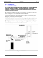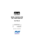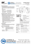
1
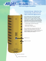
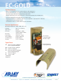
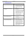
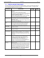
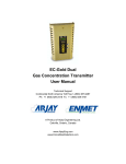
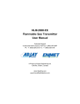
EC-Gold-NEM Gas Concentration Transmitter User Manual Technical Support Continental North America Toll Free 1-(800) 387-9487 Ph: +1 (905) 829-2418 Fx: +1 (905) 829-4701 A Product of Arjay Engineering Ltd. Oakville, Ontario, Canada www.ArjayEng.com www.EnmetGasDetection.com EC-Gold Toxic Gas/Oxygen Transmitter Economical gas detection for commercial, residential and light industrial applications Top and rear conduit knock-outs The EC-Gold is part of the Arjay series of gas detection instruments. This employs electrochemical sensors to target toxic gas or oxygen concentrations in ambient air. The unique design and flexible interface allows this transmitter to be used with any of the Arjay controllers or directly with your own site automation or control system. • multiple outputs and communications • robust metal housing • wide variety of sensor options The on-board sensor continuously monitors the ambient air by natural diffusion. The sensor responds proportionally to the gas concentration in the air. A signal is sent to the control panel or system for ventilation or alarms. Calibration port Metal sensor guard Manual test button External calibration button EC-GOLD Standard Features • Plug-in wiring terminal block for quick installation and maintenance • 1/2” and 3/4" knockouts, top, bottom, and back for easy installation • LED alarm status indication including flashing fault alarm • External calibration port for easy application of Test Gas (used with onboard CO sensor) • Protective aluminum housing with electronics filter screen • External push button for calibration (the user is not required to open the unit to calibrate) • Shielded sensor port for plug-in sensors • manual Pust-To-Test to confirm interlock of fans and alarms Technical Specifications Operating Temperature -20C to +40C, indoor use Humidity 90% non-condensing Approvals to CSA, UL Enclosure Nema/Type 1 (IP40), 197mm x 76mm x 76mm Mounting Surface mount Power Input 14-24 vdc (.1 amp) Analog Output 4-20 mA, 700 ohms Communication RS-485 Modbus Accuracy +/- 2 % of reading 24 vdc input 4-20 mA / RS-485 Modbus output Typical Gases CO carbon monoxide 0-500 ppm (factory shipped 0-200 ppm) NO2 nitrogen dioxide 0-20 ppm NH3 ammonia 0-100 ppm H2S hydrogen sulphide 0-100 ppm (factory shipped 0-10 ppm Cl2 chlorine 0-10 ppm O2 oxygen 0-30% plug-in CO sensor (3 year guarantee) combustibles refrigerants CANADA LTD. Enmet Canada Ltd is the gas detection division of Arjay Engineering Ltd. www.SkitterNet.com telephone: ++1 905-829-2418 2851 Brighton Road Oakville, Ontario N. America toll free: 1-800-387-9487 Canada fax: ++1 905-829-4701 L6H 6C9 EC11b Model: EC-GOLD NEM User Manual TABLE OF CONTENTS 1.0 2.0 3.0 4.0 INSTRUMENT OVERVIEW .............................................................................. 3 1.1 FEATURES ........................................................................................... 3 1.2 DESCRIPTION ...................................................................................... 3 1.3 SPECIFICATIONS................................................................................. 5 INSTALLATION ................................................................................................. 6 2.1 MECHANICAL INSTALLATION ............................................................ 6 2.2 ELECTRICAL INSTALLATION .............................................................. 7 STARTUP AND CONFIGURATION .................................................................. 9 3.1 NOTES ON THE USER INTERFACE OPTIONS .................................. 9 3.2 STARTUP .............................................................................................. 10 3.3 USING THE DIP SWITCH FOR SETUP ............................................... 10 3.3.1 ENTERING SETUP MODE ...................................................... 10 3.3.2 SETTING CONFIGURATION ................................................... 10 3.3.3 SETTING THE HIGH ALARM .................................................. 11 3.3.4 SETTING THE LOW ALARM ................................................... 11 3.3.5 SETTING THE CALIBRATION GAS CONCENTRATION ........ 12 3.3.6 SETTING THE NETWORK ADDRESS .................................... 12 3.3.7 EXITING SETUP MODE .......................................................... 13 CALIBRATION .................................................................................................. 14 4.1 CALIBRATION NOTES ......................................................................... 14 4.2 SINGLE POINT CALIBRATION ............................................................ 15 4.3 DUAL POINT CALIBRATION ................................................................ 15 5.0 PUSH TO TEST FEATURE .............................................................................. 16 6.0 TROUBLESHOOTING ...................................................................................... 17 7.0 CONTROLLER SETTINGS SHEET .................................................................. 18 TABLE OF FIGURES Figure 1 – TYPICAL APPLICATION ................................................................................ 4 Figure 2 – MECHANICAL INSTALLATION ...................................................................... 6 Figure 3 – ELECTRICAL INSTALLATION (EC-GOLD) ................................................... 7 Figure 4 – ELECTRICAL INSTALLATION (EC-GOLD CAP) ........................................... 7 Figure 5 – ELECTRICAL INSTALLATION (66RLU / GAS ALERT) ................................. 8 Figure 6 – USER INTERFACE OVERVIEW .................................................................... 9 Figure 7 – CALIBRATION .............................................................................................. 14 -2- Rev: 1.0 Model: EC-GOLD NEM 1.0 INSTRUMENT OVERVIEW 1.1 FEATURES 1.2 User Manual Rev: 1.0 Single gas transmitter for a large variety of gas types. Carbon Monoxide sensor has expected life of 7 years min. (3 year guarantee) Other toxic sensors have expected life of 2 years (1 year guarantee) Output may be user selectable for analog (4-20mA / 2-10V) or Arjay’s Discrete Voltage Output (DVO). Convenient pushbutton calibration. Push to test feature User selectable for Single or Dual Point calibration High, Low, and System Fault indication User selectable High and Low Alarm levels Modbus protocol via RS-485 for access by Arjay/Enmet Central Access Panel or compatible system User specified custom features may be added by contacting Arjay Engineering Ltd. DESCRIPTION The EC-Gold transmitter may be used to sense a large variety of gases including CO, NO2, Ammonia, Chlorine, and Hydrogen Sulfide (H2S), and Oxygen. The EC-GOLD sensor offers a Push To Test feature, which allows the user to check his/her alarm points to verify if the fans are working without having to gas the sensor. The analog output may be field configured either as a 4-20mA / 2-10V output or as an Arjay/Enmet Discrete Voltage Output (DVO). The DVO is a 4 level output: 0V = ok, Low Alarm = 1.8V, High Alarm = 2.8V, Sensor Fault = 10V. The DVO is a common signaling method: any sensor in a zone triggers the corresponding Low, High or Sensor Fault alarm at the Arjay/Enmet ISA-66RLU or Gas Alert alarm panel. In Discrete Voltage Output (DVO) mode, the transmitter may be connected as part of a zone connected to an Arjay/Enmet ISA-66RLU zone system. In Analog mode, the transmitter puts out a 4-20mA output proportional to the adjustable Span value. This can be used as a standalone transmitter OR hooked up to the 4200 series panels. Independent of the output type selected, the transmitter may also be accessed by an Arjay/Enmet Central Access Panel (modbus protocol) to form part of a networked gas monitoring system where up to 96 transmitters may be linked on a 2-wire RS485 connection. The networked approach allows more complex control strategies based on the gas concentrations of a number of transmitters. -3- Model: EC-GOLD NEM User Manual Figure 1 – TYPICAL APPLICATION -4- Rev: 1.0 Model: EC-GOLD NEM 1.3 User Manual Rev: 1.0 SPECIFICATIONS OPERATION The EC-Gold is a single channel gas concentration transmitter. A variety of gases may be sensed when fitted with the appropriate sensor. The output may be field selected to be one of two types: Analog 4-20mA / 2-10V, or Arjay’s RLU Discrete Voltage Output which is used in zoned alarm systems. In addition, an RS-485 interface is available so that the EC-Gold can be accessed by an Arjay/Enmet network master (Central Access Panel or CAP) or user modbus compatible system. USER INTERFACE Calibration and setup DIP switches, pushbutton, and LED status lights. Push to Test Pushbutton used to check alarm points without gasing sensors. Network RS-485 modbus protocol. Used either with the ARJAY/ENMET CAP unit or via third party, modbus compatible systems. INPUTS Integral Sensors Single sensor. Electrochemical type for gases including CO, H2S, NH3, NO, NO2 and Cl2, and O2. OUTPUTS mA output DC Voltage output When configured for Analog output: 4-20mA into 650 ohms max. When configured for Voltage output: 2-10V proportional to calibrated range. mA / Voltage output 0.1% resolution – non-isolated. RLU DVO output When configured for RLU Discrete Voltage Output mode: 0V = No Alarm, 1.8V = Low Alarm, 2.8V = High Alarm, 2.8V = HI/HI Alarm. Alarms 3 alarms (High, Low and Sensor Fault). Alarm Indication High (Red), Low (Yellow), and a 2 color LED for Sensor Fault (Red) and No Alarms (Green). The 2 color LED is also used to flash calibration errors (Red for ~2 seconds after an unsuccessful calibration). PERFORMANCE Accuracy ±2% of Full Scale Range (the accuracy is limited by the sensors – the electronic accuracy is better than 1%. POWER 15VDC - 24VDC @ 0.100A max MECHANICAL SPECIFICATIONS Enclosure Nema 1 wall mount Dimensions 7.75” [197mm]H x 3” [76mm]W x 3” [76mm]D Weight 0.3 kg ENVIRONMENTAL SPECIFICATIONS Operating Temp. Relative Humidity -20°C to +55°C 90% max. with no condensation. -5- Model: EC-GOLD NEM User Manual 2.0 INSTALLATION 2.1 MECHANICAL INSTALLATION Rev: 1.0 Figure 2 – MECHANICAL INSTALLATION Locate the EC-Gold on a vertical surface away from drafts, open doors or windows, condensation or dripping moisture. The vertical placement (above the floor) depends on the gas being monitored. For CO, the unit should be located within the breathing zone: about 900mm (3’) to 1800mm (6’) feet above the finished floor*. For other gases, refer to an Arjay Engineering representative. * Check local building codes -6- Model: EC-GOLD NEM 2.2 User Manual ELECTRICAL INSTALLATION Figure 3 – ELECTRICAL INSTALLATION (EC-GOLD) Figure 4 – ELECTRICAL INSTALLATION (EC-GOLD CAP) -7- Rev: 1.0 Model: EC-GOLD NEM User Manual Rev: 1.0 Figure 5 – ELECTRICAL INSTALLATION (66RLU / GAS ALERT) All user connections are via mating plug/receptacle connectors to make installation and service easier. CAUTION: THE UNIT HOUSES SENSITIVE ELECTRONIC COMPONENTS AND SHOULD BE HANDLED WITH CARE. IF PUNCHING OR DRILLING THROUGH THE ENCLOSURE WALLS IT IS NECESSARY MAKE SURE THAT THE INTERNAL ELECTRONIC MODULES ARE SHIELDED FROM DEBRIS ESPECIALLY METAL PARTICLES. PLEASE MAKE SURE THAT THE CONNECTIONS HAVE THE POLARITY AS INDICATED OR THE CONTROLLER MAY BE DAMAGED. USE GOOD INSTALLATION PRACTICE! DO NOT RUN HIGH VOLTAGE CABLE IN THE SAME CONDUIT AS SIGNAL WIRES. -8- Model: EC-GOLD NEM 3.0 User Manual Rev: 1.0 STARTUP AND CONFIGURATION Figure 6 – USER INTERFACE OVERVIEW 3.1 NOTES ON THE USER INTERFACE OPTIONS The EC-Gold is factory set for the requested setting at time of order. If changes are required then the EC-Gold may be configured using either of 2 methods: 1. Using the integral DIP switch: The EC-Gold front cover must be removed to access the DIP switch. 2. Using Arjay’s optional 4000-CAL hand held calibrator: The calibrator communicates with the EC-Gold via the RS-485 connection using the modbus protocol. The calibrator’s LCD and keypad offer a more convenient method of setting up and calibrating the ECGold units. See the 4000-CAL hand held calibrator manual for details if using it instead. -9- Model: EC-GOLD NEM 3.2 User Manual Rev: 1.0 STARTUP Power up the unit. The status LED should be green. The High and Low alarm LED’s should go off in less than a minute. Note: all of the following settings are preset at the factory as per the customer requirements. The settings are listed on the packing slip and may be entered in the controller setting of this manual for future reference. The following procedures should only be followed if changes are required. 3.3 USING THE DIP SWITCH FOR SETUP This DIP switch is only required if factory setup needs to change. See section 4.0 for calibration. 3.3.1 ENTERING SETUP MODE Set DIP switches 1-6 (switch 7 is not important here) to the ON position, and press the Calibration pushbutton. The Status LED starts to blink Green indicating the system is now ready to accept configuration changes. ON 1 3.3.2 2 3 4 5 6 7 SETTING CONFIGURATION While the Status LED is blinking green, set the DIP switch as follows: 1. MODE SETTINGS ON 1 2 3 4 5 6 4 Sensor supports self tests Sensor does not support self tests 5 Single point Cal 2 Point Cal 6 Continuous output mode - For mA output Sw7=Off, V out Sw7=On DVO (Discrete Voltage Output) mode. This requires Sw7 to be set for voltage output (On). 2. Single Point / Dual Point Calibration: The default position is Single Point Calibration. A Single Point calibration assumes the instrument has already been zeroed successfully. This mode saves calibration time. The Dual Point calibration is selected if the sensor has not been successfully zeroed, or if a new sensor is installed in the field. Set switch 5 On for Single Point and Off for Dual Point calibration. 3. Output Mode: In Analog output mode, the output is proportional to the gas concentration. In Discrete Voltage Output mode, the output is set to one of 4 step values based on alarms and is compatible with Arjay’s ISA 66RLU/GasAlert systems. Notes: Wire connections to the OUT terminal are dependent on the type of Output mode selected. When configured for mA out, the transmitter does not become a 2 wire Loop Powered transmitter. The mA output is referenced to the Ground terminal (Terminal #2 –see Electrical installation for terminal number details). For Analog output, switch 6 should be On and switch 7 should either be Off for 4-20mA output, or On for voltage output (2V – 10V). - 10 - Model: EC-GOLD NEM User Manual Rev: 1.0 For RLU Discrete Voltage output, switch 6 should be in the Off position, and switch 7 should be in the On position. Note: Switch 7 acts immediately and does not require configuration mode to be entered, or the Cal pushbutton to be pressed to take effect. It can be changed at any time. After switches 4 – 6 are set as required, press the Cal pushbutton to lock in the values. If finished go to exit mode (section 3.3.7) or procced with setting alarm values. 3.3.3 SETTING THE HIGH ALARM The EC-Gold will register a High Alarm condition when the sensor detects a gas concentration equivalent or exceeding this value. 1. While the Status LED is blinking green, set the DIP switch as follows: SET HIGH ALARM FUNCTION 4 56 ON 1 2 3 4 5 6 SWs 4-6 set 1 of 8 different High Alarm values: 4 56 code 0 = 5 code 4 = 75 code 1 = 10 code 5 = 100 code 2 = 20 code 6 = 150 code 3 = 50 code 7 = 200 2. Switches 4-6 should be set as per the desired High Alarm ppm value. For example to set the High Alarm value to 50 ppm, set switch 4 On, and switches 5 and 6 Off. 3. Press the Cal pushbutton to lock in the value. 3.3.4 SETTING THE LOW ALARM The EC-Gold will register a Low Alarm condition when the sensor detects a gas concentration equivalent or exceeding this value. 1. While the Status LED is blinking green, set the DIP switch as follows: SET LOW ALARM FUNCTION 4 56 4 56 ON 1 2 3 4 5 6 SWs 4-6 set 1 of 8 different Low Alarm values: code 0 = 1 code 4 = 20 code 1 = 2 code 5 = 25 code 2 = 3 code 6 = 35 code 3 = 10 code 7 = 50 2. Switches 4-6 should be set as per the desired Low Alarm ppm value. For example to set the Low Alarm value to 35 ppm, set switches 4 and 5 Off, and switch 6 On. 3. Press the Cal pushbutton to lock in the value. - 11 - Model: EC-GOLD NEM 3.3.5 User Manual Rev: 1.0 SETTING THE CALIBRATION GAS CONCENTRATION This value tells the EC-Gold what the value of gas concentration will be used during calibration. 1. While the Status LED is blinking green, set the DIP switch as follows: SET CAL CONCENTRATION FUNCTION ON 1 2 3 4 5 4 56 4 56 6 SWs 4-6 set 1 of 8 different Cal2 values: code 0 = 5 code 4 = 35 code 1 = 10 code 5 = 50 code 2 = 20 code 6 = 75 code 3 = 25 code 7 = 100 2. Switches 4-6 should be set as per the desired calibration gas ppm value. For example to set the value to 100 ppm, set switches 4, 5, and 6 Off. 3. Press the Cal pushbutton to lock in the value. 3.3.6 SETTING THE NETWORK ADDRESS This value is only used in network applications. Each EC-Gold transmitter connected on a network must have a unique address. Note: the maximum address that can be entered via the DIP switches is 31. To set values up to 96, use the Arjay/Enmet EC-Gold hand held calibrator. Network problems will result if 2 or more transmitters have identical addresses. 2 34 5 6 SET RS-485 ADDRESS FUNCTION 2 34 5 6 2 34 5 6 2 34 5 6 =1 =9 = 17 = 25 =2 = 10 = 18 = 26 =3 = 11 = 19 = 27 =4 = 12 = 20 = 28 =5 = 13 = 21 = 29 =6 = 14 = 22 = 30 =7 = 15 = 23 = 31 =8 = 16 = 24 ON 1 2 3 4 5 6 SWs 2-6 set 1 of 31 different addresses 1. While the Status LED is blinking green, set the DIP switch as follows: 2. Switches 2-6 should be set as per the desired number between 1 and 31. For example to set the address to 5, set switches 2, 3, and 5 On and switches 4 and 6 Off. 3. Press the Cal pushbutton to lock in the value. - 12 - Model: EC-GOLD NEM 3.3.7 User Manual Rev: 1.0 EXITING SETUP MODE After all configuration is done, the setup mode must be exited for normal operation. Also, calibration cannot be done via the Calibration pushbutton while in setup mode. To exit setup mode (i.e. Status LED is blinking green), set the DIP switches 1-6 (switch 7 is not important) to the ON position, and press the Calibration pushbutton. The Status LED should remain steady green. ON 1 2 3 4 5 6 7 IMPORTANT: after exiting the setup mode, do not leave the DIP switches (1-6) in the ON position as shown above. This will cause entry to Setup mode if calibration is attempted (i.e. if Calibration pushbutton is pressed). Set all switches (1-6) in the off position. FOR EXAMPLE, LEAVE THE DIP SWITCH IN THE FOLLOWING POSITION FOR NORMAL OPERATION: TYPICAL SETTING FOR NORMAL OPERATION ON 1 2 3 4 5 6 7 THIS COMPLETES THE STARTUP AND CONFIGURATION - 13 - Model: EC-GOLD NEM 4.0 CALIBRATION 4.1 CALIBRATION NOTES User Manual Rev: 1.0 The EC-Gold may be calibrated using either a Single Point (Preferred Method) or Dual Point calibration procedure. The factory setting is for a single point calibration i.e. calibration can be performed without removing the cover using calibration port and access hole. The Calibration pushbutton may be accessed using a screwdriver or other fine tool – See Figure 6 or 7 for the location of the access hole. For single point calibration, the factory setting requires a 100ppm CO concentration gas or 10ppm NO2 . Consult factory for other toxic gases. A full Dual Point calibration is always performed at the factory and involves zeroing the sensor in clean air, then calibrating at a preset gas concentration. The Single Point calibration is typically used in the field since it is more convenient. Also, it does not require clean air as one of the calibration points, since clean air cannot be guaranteed in all installations. A Single Point calibration assumes the unit has already been zeroed. This is always true for new units from the factory. Figure 7 – CALIBRATION - 14 - Model: EC-GOLD NEM 4.2 User Manual Rev: 1.0 SINGLE POINT CALIBRATION The EC-Gold must be configured for Single Point calibration (factory default), and the calibration gas concentration value must be known. The unit comes factory set for Single Point Calibration and 100 ppm CO or 10 ppm NO2. If either setting is in doubt, then see section 3 to set these values. 4.3 1. Determine what Calibration gas concentration the EC-Gold is expecting. This value is listed on the packing slip and may be recorded in the back of the user manual in the CONTROLLER SETTINGS sheet for future reference. This value can be changed at any time as described in SETTING THE CALIBRATION GAS CONCENTRATION section described earlier. 2. The gas sensor is mounted directly behind the Calibration Port in the middle of the front plate of the EC-Gold housing [See Fig. 7]. Insert the Quick Disconnect tube into the EC-Gold’s Calibration Port. 3. Start gassing the sensor by opening the valve on the canister. The flow rate is preset to 0.5 Lpm (or ~1 SCFH (Standard Cubic Foot per Hour). Wait about 90 seconds. 4. Press and hold the calibration pushbutton (via the access hole – see Fig. 6) until the Status LED glows orange acknowledging the calibration request. Release the pushbutton. 5. If the Status LED blinks green 3 times after the Calibration pushbutton is released, then the Calibration has been successfully completed. If the calibration was successful, the Status LED will return to steady green. 6. If the status LED blinks dark red 3 times after the Calibration pushbutton is released, then there was a calibration error such as not enough change for the gas concentration used. For unsuccessful calibrations, the original calibration values remain unchanged. For example, if the EC-Gold calibration gas is set as 100 ppm via the DIP switches (this is described earlier), but the actual gas used is only 20 ppm then the calculated sensitivity will be out of allowed limits and will cause a calibration error. The Status LED will blink dark red 3 times, but the new erroneous calibration values will be discarded and the Status LED will return to steady green. 7. If the Status LED does not glow orange, and continuously blinks green after the Calibration pushbutton is released, then the DIP switches (1-6) are probably set to Enter Setup Mode i.e. all of them are set to ON. If this is the case, shut off the calibration gas and press the Calibration pushbutton to exit the Setup Mode, then set DIP switch 1-6 to OFF. DUAL POINT CALIBRATION This procedure is typically done at the factory. The Dual Point calibration not only trims the sensitivity (like a Single Point calibration), but also zeroes the reading i.e. 0 ppm in clean air. Dual point calibration in the field requires a handheld calibrator. THIS COMPLETES THE CALIBRATION PROCEDURE - 15 - Model: EC-GOLD NEM 5.0 User Manual Rev: 1.0 PUSH TO TEST FEATURE The Push to Test feature allows the customer to verifty if the controller is receiving a LOW, HIGH and HIGH HIGH (Total span) alarm signals and that ventilation fans, audio alarms etc are working. Press the Push to Test pushbutton to activate this feature. See Figure 5 for the pushbutton location. When the button is pressed and released, the Status LED starts blinking green on and off every 2 seconds to indicate a test is underway. This feature forces the sensor to to Low alarm plus 1ppm. Press Button again to force High alarm plus 1ppm. Press Button again to force HIGH HIGH alarm (Total span plus 1 ppm). Press Button again to get out of Push to Test feature. If Push to Test feature is left ON, it will time out after 30 minutes. - 16 - Model: EC-GOLD NEM 6.0 User Manual Rev: 1.0 TROUBLESHOOTING ERROR DESCRIPTION WHAT TO DO Check the power to the unit. The voltage should be 24VDC at the power connector with the positive and negative connected as shown on the connector label. If the Power checks out, call Arjay Service. Make sure that DIP switch 7 is set to Off (down) position. Make sure that the EC-Gold output mode is set to Analog mode and not to Discrete Voltage Output mode. See SETTING CONFIGURATION section for details. Calibration may be required. See the calibration section for details. Call Arjay/Enmet Service for Help if none of the above fix the problem. 3. In Discrete Voltage Output mode, the ISA66RLU or Gas Alert connected to the ECGold always shows Sensor Fault Make sure that DIP switch 7 is set to the On (up) position. Make sure that the EC-Gold output mode is set to Discrete Voltage Output mode and not to Analog. 4. When pressing the Calibration pushbutton there is no calibration acknowledge (i.e. the Status LED does not glow orange) Make sure the calibration pushbutton is pressed for at least 2 seconds. Make sure that the DIP switches 1-6 are not all On (Up). This will cause the Setup mode to be entered when the pushbutton is pressed. If the Status LED is flashing green, first press the calibration pushbutton to exit the Setup mode, then set switch 6 to the Off (down) position. Then proceed with the calibration procedure. 1. No Output and all lights off 2. 4-20mA output does not track the gas concentration. - 17 - Model: EC-GOLD NEM 7.0 User Manual Rev: 1.0 CONTROLLER SETTINGS SHEET The factory settings column below lists the typical default settings. The user may change these values at any time either by the integral DIP switches or via the EC-Gold hand held calibrator. If changed, please fill in the USER SETTING column for future reference. PARAMETER OUTPUT MODE VOLTAGE / CURRENT OUTPUT CALIBRATION TYPE DESCRIPTION There are 2 main output modes which may be field selected: Analog: the output is proportional to the gas concentration. The output type may be further selected to be mA type (4-20mA) or voltage type (2V-10V) – see Voltage / Current Output setting. Discrete Voltage Output mode: the output is compatible with Arjay’s ISA 66RLU/Gas-Alert Alarm system. If Analog output mode is selected, then the type of output may be further selected to be current type (4-20mA) or voltage (2V – 10V). Note: if the Output type is RLU discrete voltage, then this setting MUST be voltage type. Field selectable for either Dual Point, or Single Point. The Dual Point type zero’s and spans the instrument. The Single Point type assumes the zero has been successfully done, and only spans the instrument. FACTORY SETTING As per order As per order Single Point HIGH ALARM The value in ppm at or above which a High Alarm condition is entered. As per order LOW ALARM The value in ppm at or above which a Low Alarm condition is entered. As per order CALIBRATION GAS The calibration gas value in ppm. This value is assumed by the EC-Gold during calibration. Note: for Single Point calibrations, this is the only gas used. For Dual Point calibrations, the first gas is always assumed to be clean air (0 ppm) As per order This value is only pertinent if Analog Output has been selected. It is the full scale value in PPM at which concentration the EC-Gold output is at its maximum: 20mA (current type) or 10V (voltage type). Note: this value cannot be set via the integral DIP switches. It can only be set via the EC-Gold hand held calibrator or EC-Gold Central Access Panel. Only required for network applications (where the RS485 bus is used). The Address is used by the EC-Gold calibrator or by the EC-Gold Central Access Panel to access each EC-Gold transmitter on a network. Each EC-Gold on a network must have a unique address number from 0 – 96. Note: the maximum address value which can be set by the integral DIP switches is 31. To set values higher than this, use the EC-Gold hand held calibrator. As per order CONCENTRATION SPAN VALUE NETWORK ADDRESS - 18 - As per order USER SETTING MAINTENANCE AND CALIBRATION Your ARJAY / ENMET gas detector is the state of the art in gas detection, but like any other part of your ventilation system, it requires periodic maintenance and calibration. There are various sensor technologies that may be used in your Arjay gas monitor; including solid state MOS, Electrochemical, Infrared and Pellister Pair (Hot wire). These have a normal operating life of 3 to 5 years under ambient conditions. You should consider a preventive maintenance schedule whereby you test your system on a periodic basis to ensure its proper calibration and operation. For solid state (MOS) sensors, we recommend calibration every 3 to 4 months for a typical garage application. For Electrochemical sensors, we recommend calibration every 6 months for a typical garage application. Pellister Pair we recommend every 3 to 4 months and Infrared we recommend every 6 months. For applications that are more sensitive, or where internal policies exist, a higher frequency of calibration may be required. This is a simple procedure which will indicate any problems with your system. A test and calibration kit may be purchased from ARJAY ENGINEERING for this purpose. Parts are also readily available from our facility. MAINTENANCE CONTRACT Alternatively you may wish to consider a Maintenance Contract with ARJAY ENGINEERING whereby one of our service technicians comes to your site and checks out the unit for proper calibration and operation on a regularly scheduled basis. This is done on a flat per annum fee. All parts are extra. Typical target gases are included, however, exotic or specialty gases may have a surcharge. If you wish us to quote a Maintenance Contract fill in the section below and return to our office. COMPANY: ADDRESS: CONTACT PERSON: PHONE: FAX: EMAIL: MODEL AND SERIAL NO. OF GAS DETECTOR: Fax to address below or e-mail to [email protected] ARJAY ENGINEERING LTD 2851 Brighton Rd Oakville, Ontario, Canada L6H 6C9 Telephone: +1 (905)-829-2418 Telefax: +1 (905)-829-4701 N. America Toll: (800)-387-9487 Internet: www.arjayEng.com E-Mail: [email protected] ARJAY ENGINEERING LTD. GUARANTEE We hereby guarantee this instrument to be free from defects in workmanship and materials, and if found defective in workmanship or materials, upon being returned to our factory, prepaid, within one year from date of purchase, it will be repaired or replaced at factory without charge. However, if upon being returned and after inspection, there is evidence that the instrument has been subjected to tampering, careless handling, improper or faulty application or installation, the above guarantee shall not be applicable, and we shall have the right in any such case to make a charge to cover the cost of repairs, servicing and transportation expense. The undersigned assumes and shall have no liability for consequential damages resulting from the use or misuse of the instrument. The foregoing guarantee is in lieu of all other guarantees or warranties, expressed or implied, and all other obligations or liabilities, contractual or otherwise, either to the original purchaser of said instrument, or to any other person whomever. BY: ARJAY ENGINEERING LTD. For service, call ARJAY Engineering Ltd. directly: Canada (905) 829-2418 North American Toll Free: 1-800-387-9487 Fax: (905) 829-4701 Internet: www.arjayeng.com E-mail: [email protected] ARJAY ENGINEERING LTD 2851 Brighton Rd Oakville, Ontario, Canada L6H 6C9 Telephone: +1 (905)-829-2418 Telefax: +1 (905)-829-4701 N. America Toll: (800)-387-9487 Internet: www.arjayEng.com E-Mail: [email protected]