1
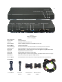
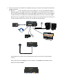
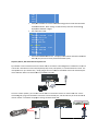
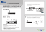
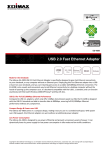
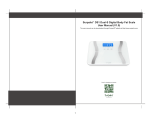
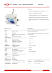
InternetVue™ HD Multimedia Extender DT11‐KIT DT11‐RX DT11‐TX DT70‐TX User Manual v1.0 Introductio on Thank you for purchasingg the DT11 Mu ultimedia Exten nder. With thee DT11, you can n send high‐deefinition audio and m one or more sources to onee or more displlays over an Etthernet network. Furthermo ore, the DT11 ccan video from also relay IIR remote conttrol signals, as well as PS/2 keeyboard and m mouse inputs frrom a remote display locatio on to a source PC or consumer e electronics devvice. IN OR RDER TO O PREVEENT DAM MAGE, READ THIIS MANU UAL IN ITTS ENTIRETY BEEFORE ATTTEMPTTING TO CONNECT OR P POWER U UP ANY SING A GLE DEV VICE OR C COMPONENT! Hardware Remote On/Off switch h put VGA passs‐through outp RJJ45 network jaack DC input jack DVI/VGA select sw witch USB to PC Ext. IR port DVI‐I video input DT11‐TX On ne‐port Transm mitter (P PCA – PC Adap pter) STTATUS LED R LED POWER Audio porrts Reset butto on STATU US LED Rem mote On/Off switch POWER LED DC inp put jack Extt. IR jack DVI‐I video input Reset button n 7x 10//100 Ethernet ports U USB to PC DVI/VGA Audio ports VGA paass‐through DT70‐TX Seven‐port Transmitter CA – PC Adapteer) (PC Port / Connector DC input Jaack USB to PC n/Off Remote On External IR R port VGA pass‐tthrough DVI/VGA select DVI‐I inputt Status LED D Power LED Audio portts Reset button port(s) Ethernet p RIES: ACCESSOR IR Transm mitter Purpose 5V DC poweer input Keyboard an nd mouse input to PC Enables / Dissables peripheerals connected d to receiver unit Connects to IR emitter ocal VGA monittor. Works onlly if source is aalso VGA. Allows you tto connect a lo Selects betw ween the VGA o or the DVI‐D pins on the DVI‐‐I input connecctor Video signal input – utilizees either DVI‐D or the VGA siggnals through tthe select switch Displays network connectiion status wer and operattion mode stattus Displays pow Audio signal input from so ource to RX (speaker), and ou utput audio from RX to PC (m mic) operation mod de selection Resets unit, and provides o on(s) to RX unit(s) through LA ANs or direct connections 10/100 Etheernet connectio External IR Receiver VGA‐M to DVI‐F adapter DV VI‐M to VGA‐F adapter Cables IR receiver w window External IR jack URCE button SOU POWER LED D S STATUS LED DC input jack PS/2 keybo oard and mousse ports RJ45 ne DVI‐I vid etwork jack deo output Audio ports Reset button Port / Connector DC input Jaack PS/2 conneectors IR receiverr window External IR R jack Source buttton DVI‐I outpu ut Status LED D Power LED Audio portts Reset button port Ethernet p DT11‐RX One‐port Receeiver O ((TVA – TV Adap pter) Purpose 5V DC poweer input PS/2 keyboaard and mouse input for remote PC control Receives IR rremote contro ol signals Connects to external IR recceiver Multifunctio on button that allows selectio on of various sources and oth her functions Video signal output – transsmits both DVI‐D and VGA signals simultan neously Displays network connectiion status wer and operattion mode stattus Displays pow Audio signal input from mic to TX, and output audio fro om TX to speakers operation mod de selection Resets unit, and provides o on from TX uniit(s) through LA AN or direct co onnection 10/100 Etheernet connectio Features and Specifications Very low latency Audio / SD and HD Video transmission over Ethernet networks Send video from multiple sources to multiple destinations over the same Ethernet network Adjustable bandwidth Receivers can select which source transmitter to display using pushbutton and OSD Standard 38 kHz IR remote control repeater from receiver back to transmitter Accepts VGA and DVI‐D input signals, including HDMI (NOTE: HDCP and digital audio are not supported, and requires DVI‐HDMI adapter, not included) Accepts stereo audio input Works with any computer operating system Remote On/Off switch at transmitter disables peripherals connected to receiver Relays mic input from receiver back to transmitter Transmitter accepts video resolutions from 640 x 480 to 1920 x 1080, from 60Hz to 70Hz refresh Built‐in scaler scales output video to display’s capability regardless of input video resolution Receiver output resolutions and frame rates are as follows: o 1360 x 768 30 fps o 640 x 480 70 fps o 1400 x 1050 30 fps o 720 x 480 60 fps o 1440 x 900 30 fps o 720 x 576 50 fps o 1600 x 1200 30 fps o 800 x 600 70 fps o 1680 x 1050 30 fps o 1024 x 768 60 fps o 1920 x 1080 25 fps o 1280 x 720 30 fps o 1280 x 1024 30 fps Receiver outputs both DVI‐D and VGA signals, regardless of input signal on transmitter Built‐in browser‐based configuration for easy user‐setting of “Operational IP address” and device naming Permanent, hard‐coded “Setup IP address” are as follows: o Transmitter (PCA) 192.168.168.21 o Receiver (TVA) 192.168.168.22 STATUS LED colors: o Off No network connection o Green Network connected o Blinking green Network activity o Orange/Red High network bandwidth usage POWER LED colors: o Off Unpowered o Green Powered on and connection established with corresponding TX or RX unit o Red Powered on, but no connection to corresponding TX or RX unit o Blinking Red Reset button held down, ready to enter Setup mode o Orange Unit is in Setup Mode Configurattion and Setup p 1. You w will need to set fixed IP addressses for each o of your DT11 deevices. This is necessary for proper operattion, and so o that the DT11 1 units will nott interfere with h any other devvices on your n network. However, you can sskip settingg the IP addressses on the uniits, and go to SStep 2, only if: The TX and RX units aare connected only by an Eth hernet cable, w with no router o or switch in betwee en (one‐to‐onee operation): DT11‐TX DTT11‐RX or more RX units are connectted through a sswitch, but no PCs There is only one TX unit, and one o or routters are conneccted to that sw witch (one‐to‐m many operation n): DT11‐TX DTT11‐RX DTT11‐RX There is only one TX unit, and one o or more RX units are connectted through a sswitch. PCs an nd/or routerss are connected to that switcch, but reside o on a subnet oth her than 192.1 168.168.x (one‐to‐ many o operation): DT11‐TX DT11‐RX DT11‐RX PCs on 192 2.168.1.x subnet . . . . . . 1.1. FFirst, you will n need to connecct a computer using an Ethernet cable to eaach DT11 (TX aand RX) unit in order t to access its co onfiguration weeb page. In your computer’s network adap pter settings, give it a fixed IP P a address of 192 .168.168.100, subnet mask 2 255.255.255.0. In n Windows XP, this can be do one using the fo ollowing proceedure: 1..1.1. Go to CON NTROL PANEL > NETWORK CONNECTIONS > right‐click LO OCAL AREA CON NNECTIONS, th hen click on STTATUS. Click o on the PROPER RTIES button, sccroll‐down, and double‐click on “Internet Protocol ((TCP/IP)”. In th he next window w, enter the IP P address and ssubnet as show wn below: 1..1.2. Click OK, tthen OK, then CLOSE. 1.2. Now, prepare t N the DT11 (or D DT70) unit to bee configured an nd a small blun nt instrument ssuch as a tooth hpick o or straightened d paperclip. M Make sure the u unit is unpowerred and not co onnected to anything. 1.3. Using the blunt U t instrument, h hold down the RESET button,, then power o on the unit by p plugging in thee p power adapter r. When you seee the POWER LED blink RED D, release the R RESET button, tthen the POWEER L LED should turn n ORANGE. On nly when the P POWER LED is O ORANGE can yyou access the unit’s configurration w web page, also o known as Setu up Mode. 1.4. N Next, connect tthe unit to you ur computer ussing any standaard Ethernet caable. Once thee cable is c connected, the e STATUS LED tturns green. 1.5. O Open a browse er, and enter th he following “SSetup IP addresss”, dependingg if the unit you u are configuring is a a transmitter o or a receiver: 1..5.1. Transmittter (PCA) 192.168..168.21 1..5.2. Receiver ((TVA) 192.168..168.22 e settings web page where you can enter the “Operational IP address”.. This address is in 1.6. YYou will see the e effect only whe en the device is in normal AV V operation (wh hen POWER LEED is not ORAN NGE), and is d different from up IP the “Setup IP aaddress” abovee, which is perrmanent and caannot be changed. The “Setu a address” in effe ect only when the POWER LEED is ORANGE. Even if you haave set an “Op perational IP a address” previo ously, enteringg this Setup mo ode will revert all settings back to the facto ory defaults: Now, you can enter an IP address for this unit, and also a friendly device name. Some rules‐of‐thumb: Because the DT11 / DT70 units will not be interacting with any other devices on your network, the IP address should be on a subnet which is currently not used by any device on your network. For example, if your router and DHCP server use the 192.168.1.x subnet, you set all your DT11 / DT70 devices to another subnet, such as its current factory subnet 192.168.168.x. However, be sure that every DT11 / DT70 unit has a unique address. For the Device Name, use a descriptive name which can easily be identified by the user. See example below. Permitted IP Address Ranges: 192.168.0.0 to 192.168.254.254 172.16.0.0 to 172.31.254.254 10.0.0.0 to 10.254.254.254 When done, click on SAVE, then EXIT. The unit will restart. 1.7. Disconnect the Ethernet cable from your computer and the unit. The DT11 / DT70 unit is now configured with the IP address 192.168.168.200, and Device Name “Lobby TV”. 1.8. Repeat steps 1.2 to 1.7 for all DT11 / DT70 units in your setup, making sure each unit has a different IP address, but MUST HAVE the same first three octets (ie. 192.168.168.x). Here is an example: Device Name IP Address Unit Type DT11‐RX Lobby TV 192.168.168.200 DT11‐RX Upstairs TV 192.168.168.201 DT11‐TX DVD‐Player‐1 192.168.168.202 DT11‐TX DVR 192.168.168.203 1.9. Go back to the TCP/IP properties window as shown in step 1.1.1 above, and change it back to “Obtain an IP address automatically”. Click OK, then OK, then CLOSE. 2. Now that all your DTT11 / DT70 devvices are configgured properlyy, you can begin connecting aall the hardwarre and herals togetherr. periph 2.1. Receiver: R ur display to th he receiver’s DV VI‐I port. You may need a DV VI‐VGA adapteer, or Connect you D DVI‐HDMI adap pter. Next, plu ug in the speakkers or audio am mplifier to the Audio Out jack of the receivver. If y you are using a a keyboard and d/or mouse, yo ou can plug tho ose into the recceiver as well. If you are usin ng the IR repeater fun nction, you can n either just usee the built‐in IR R window on the receiver, orr use the includ ded e external receiv ver, and plug th hat into the Extt IR port in fron nt. If you are u using the devicce on a networrk, you c can plug an Eth hernet cable into the receiver now, and thaat cable into th he network. DT11‐RX DT11‐RX ll‐in‐one cable can be used to T The included a o extend the devices if the DT11‐RX is in an n inaccessible location. L Lastly, power u up the unit by p plugging in its power adapterr. The POWER R LED should bee RED, and the S STATUS LED sh ould be GREEN N. DT11‐RX 2.2. TTransmitter: The included d cable is used to convenienttly connect a P PC to the transm mitter Connectt your c computer or so ource device to o the transmittter’s DVI‐I portt. You may neeed a DVI‐VGA o or DVI‐HDMI a adapter. If the signal comingg from the sourrce is DVI or HD DMI, be sure to o set the DVI/V VGA switch to DVI. If the signal is V VGA, set the sw witch to VGA. Next, plug onee end of the au udio cable into the Audio In jaack on t the transmitter r, and the otheer end into you ur computer orr source devicee’s Line Out or Speaker Out jaack. T The audio cable e also has a paass‐through fem male connecto or for a local sp peaker connecttion. If you aree u using a keyboa rd and/or mou use, plug in thee USB cable intto the USB portt on the transm mitter, and thee o other end into a free USB porrt on your com mputer. If you aare using the IR repeater fun nction, plug thee included IR emitter into the IR Out jack, and d point the IR eemitter to the device being ccontrolled. If yyou a are using the d net cable into tthe receiver no ow, and that caable evice on a network, you can plug an Ethern into the network, or you can plug the otherr end directly into the transm mitter. DT11‐TX Local speaker Audio output Line‐In or Miic input DVI or VGA output USB Setup p with a PC DT11‐TX Local speaker Steereo Ou ut HDMI‐DVI‐I Adapter (not included) Setup with a Consumer Electronics device e VD player with HDMI outputt such as a DV HDMI Out At this point, yo A ou can also plu ug in a local VG GA monitor to tthe transmitteer. But note that the local VG GA m monitor will on nly work if the input signal is also VGA. DT11‐TX L Lastly, power u up the unit by p plugging in it’s power adapteer. The POWER R LED should b be RED, and thee S STATUS LED sh ould be GREEN N. D DT11‐TX 2.3. D DT70 Transmittter: Thee DT70‐TX is identical as the D DT11‐TX, except that it has aa built‐in 7‐portt E Ethernet switch h with IGMP sn nooping, designed specifically for use with multiple DT11 1 units. You can plug s seven other DT T11 devices dirrectly into the D DT70‐TX, witho out the need fo or additional n network hardw ware. DT70 0‐TX D DT11‐RX DT11‐R RX . . . Directt to receivers A AND/OR To other switches DT11‐R RX 2.4. Repeat steps 2 R .1 to 2.3 abovee for all DT11 // DT70 devices that would bee in use. 2.5. IIMPORTANT: W WHEN USING M MULTIPLE TRA ANSMITTERS O ON THE SAME N NETWORK T Transmitters ca an consume up p to 99% of avaailable bandwidth on a 100M Mb/s Ethernet llink when runn ning at 1 1080p. Therefo ore, the ideal m method of con nnecting multip ple transmitterrs to multiple rreceivers is to h have a all transmitters s connected to o a single switch using a direcct connection, w without any ad dditional 100M Mb/s s switches in bet tween. This en nsures that eacch transmitter has a full 100M Mb/s link to the switch: DT11‐TX DT11‐RX 100Mb/ss 100Mb/ss 100Mb/s b/s 100Mb DT11‐RX DT11‐TX 100Mb b/s switch with h DT11‐RX 100Mb/ss DT11‐TX 100Mb/s IGMP ssnooping A An alternative is to have a Giggabit link in beetween switchees to accommo odate the additional bandwid dth u used by the mu ultiple transmittters: 100 0Mb/s switch w w/ gigabit port DT11‐TX 100Mb b/s and d IGMP snoopin ng DT11‐TX DT11‐TX 100Mb/ss 100Mb/s 1000Mb/ss 100Mb//s 100M Mb/s DT11‐RX 100M Mb/s switch w/ gigabit port and IGMP snooping DT11‐RX 100Mb//s DT11‐RX Most importanttly, switches ussed with multip M ple DT11 / DT7 70 transmitterss must have “IG GMP snoopingg” fu unctionality. This is critical in n preventing m multiple multicaast streams fro om flooding thee entire netwo ork, caausing all other network deviices such as co omputers to haave slow or no access to the n network. The IGMP sn nooping featurre in switches intelligently ideentifies and routes the AV paackets from thee transmitters only to o the appropriaate DT11‐RX deestinations, no ot to computerrs that don’t neeed it. This freees up bandwid dth th hereby allowing other network traffic to paass. OSD Functtions The DT11‐RX includes an n On‐Screen Dissplay (OSD) meenu which is en nabled by he SOURCE buttton on the fro ont panel. The OSD menu pro ovides the pressing th user with vvarious settings and the abilitty to select wh hich source video stream to display. SOUR RCE button 1. Press the SO OURCE button n to cycle throu ugh the variou us options. To select an n item, leave tthe desired item highlighted for three seco onds. DT11‐‐RX (TVA) Setup via OSD To sett the options off the DT11‐RX (TVA) unit, maake sure that th he DT11‐RX is not connected d to the networrk. Powerr it up with a display, and thee following message will appeear: SEARCHI ING PCA . . . NOT FOUN ND Wait aa few seconds until the message disappearss, the press thee SOURCE buttton to bring up p the OSD: > REFRESH > TVA S SETTING > TVA O OFF network again for any enableed DT11‐TX (PC CA) units REFRESH will search the n NG brings up th he options for tthe DT11‐RX. SSelect this optiion to go to the next menu b below TVA SETTIN TVA OFF dissables the DT1 11‐RX from disp playing any vid deo or audio > AU UDIO INPUT > IR R INPUT > RE ETURN AU UDIO INPUT brings up the MIC input settinggs menu, see b below IR INPUT brings u up the IR remo ote input menu u settings menu, see below menu REETURN goes to the previous m > MIC IN N DISABLE > MIC IN N ENABLE > RETURN N MIC IN DISABLE turns off the MIC input to save bandwidth MIC IN ENABLE turns o on the MIC inp put RETURN N goes to the p previous menu > IR DIS SABLE > INTERN NAL IR > EXTERN NAL IR > RETURN N BLE turns off th he IR repeater to save bandw width IR DISAB INTERNAL IR enables tthe IR repeater using the front‐panel IR recceiver NAL IR enables the IR repeateer using the extternal IR jack EXTERN RETURN N goes to the p previous menu 2. Run‐time OSD When the DT11‐RX is streaming video from a source transmitter, the OSD options are different than in #1 above. Again, pressing the SOURCE button brings up the OSD: > DVD‐1 (00:00:20) connected > APPLE‐3 (00:00:26) > REFRESH > VGA SYNC > PCA SETTING > TVA OFF > EXIT In the Run‐Time OSD, the list of available transmitters is listed first. In the example here, two transmitters are shown, “DVD‐1” and “APPLE‐3”. The numbers in the parentheses are its MAC addresses. The “connected” status indicates that this DT11‐RX unit is currently showing the AV stream from the transmitter “DVD‐1”. To select another transmitter’s content to display, simply press the SOURCE button again until it is highlighted, wait three seconds, and its stream will be shown instead. VGA SYNC (appears only if input at transmitter is VGA) re‐synchronizes VGA signal REFRESH will search the network again for any enabled DT11‐TX (PCA) units PCA SETTING brings up the options for the currently selected transmitter. Select this option to go to the next menu below TVA OFF disables the DT11‐RX from displaying any video or audio EXIT turns off the OSD > MULTI/ONE TVA > BANDWIDTH SETTING > INFORMATION > EXIT MULTI/ONE TVA brings up the MULTI/ONE menu below BANDWIDTH SETTING brings up the BANDWIDTH menu below INFORMATION displays the current operating modes of both the receiver and currently selected transmitter EXIT turns off the OSD > ONE TVA ONLY > MULTI TVA > EXIT ONE TVA ONLY sets the currently selected transmitter to Unicast mode wherein only this receiver can display that transmitter’s content MULTI TVA sets the currently selected transmitter to Multicast mode wherein more than one receiver can display that transmitter’s content EXIT turns off the OSD > LOW > MID > HIGH > EXIT LOW, M MID and HIGH aare various ban ndwidth settinggs which can b be selected to ssave networkk bandwidth. TThese settings are effective o only when the content beingg displayeed is 1280x720 0 or higher EXIT turrns off the OSD D PCA COL VERSION N 0.91 PROTOC SUPPOR RT MULTI TV VA BANDIW WDTH High DVI IN N 1024*768 aster TVA – Ma PROTOC COL VERSION N 0.91 DVI OU UT 1024*768 8 MIC IN N INTERN NAL IR Here is tthe INFORMATTION screen. It displays all th he relevant infformation abou ut the DT11‐RX X (TVA) and the currently selected transmittter (PCA). Keyboard, Mouse, Mic aand IR Remote Repeater Use e der to control the transmittin ng device conn nected to a DT1 11‐TX Input devicces can be connected to the DT11‐RX in ord or DT70‐TX X. These devicces can be a PS/2 keyboard, P PS/2 mouse, m microphone, or standard IR reemote control. The microphon ne is set up in aa similar way –– simply plug in n the mic or oth her low‐level aaudio source in nto the MIC‐IN jack on the DT1 11‐RX. Make sure that the M MIC IN is enableed in the OSD. DT11‐RX As for the remote repeatter, you can eitther use the bu uilt‐in or external IR receiver on the DT11‐R RX side. On the ng side, plug in n the included IR transmitter into the IR OU UT port, and aim m it directly at the AV devicee’s IR transmittin receiver window. Ensure e that the prop per IR setting iss selected in th he OSD. DT11‐RX DT11‐TTX Simply plug in the PS/2 d devices into theeir respective p ports on the trransmitter, theen power up th he receiver. On n the mitter’s USB porrt to an unused d USB port on the transmitter side, use the included USB cable to conneect the transm computer. Your computer may prompt you that it haas detected neew hardware, sso just follow the prompts to n process. complete tthe installation DT11‐TX USB One imporrtant note whe en using multip ple receivers peer transmitter:: Only the MASSTER DT11‐RX will have the functional keyboard, mouse, and IR port with respectt to each transsmitter. To sett which DT11‐R RX is the MASTER unit, turn o off all other DTT11‐RX units, p power up the desired unit firsst, and allow it to establish a connected to the transmitter. See the INFORMATION OSSD screen abovve on how to d display the DT1 11‐RX’s MASTEER/SLAVE statu us. When the desired DT11‐RX unit is alreaady set as MASSTER, all other DT11‐RX unitss can be powerred up. DT11‐TX PC 100M Mb/s switch MASTTER unit – conne ected 1st DT11‐RX DT11‐RX DT11‐R RX SLAVEE units ‐ conneected after MASTER Remote On – Off Switch Each DT11‐TX / DT70‐TX transmitter un nit has a front‐‐panel REMOTEE ON/OFF switch. This switch h disables all in nput devices (keeyboard, mousse, and IR remo ote control on a Master DT11 1‐RX) from con ntrolling the co omputer or AV device con nnected to the transmitter. Remote On/Off switch DT11‐RX X For technical support, please visit www.addlogix.com/wbs ©2009 atBox Technology Inc. No part of this User Guide can be copied, reproduced, transmitted, or otherwise used without the prior written consent of atBox Technology Inc.