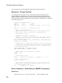
1
Simulator Reference Manual
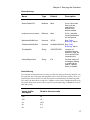
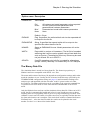
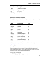
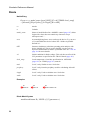
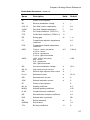
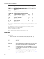
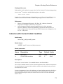
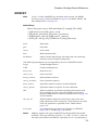
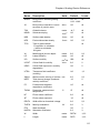
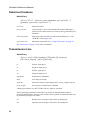
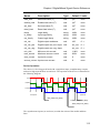
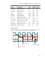
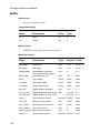
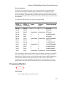
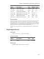
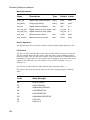
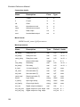
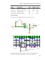
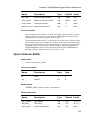
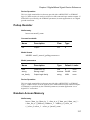
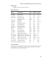
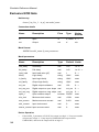
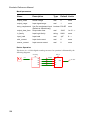
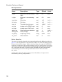
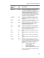
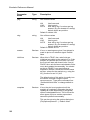
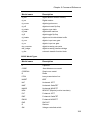
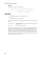
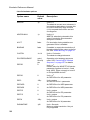
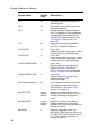
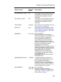
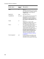
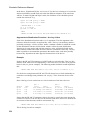
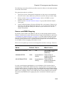
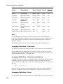
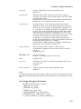
Model parameters
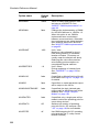
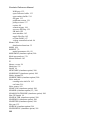
Name
Description
Type
Default Limits
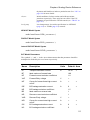
in_low
Maximum 0-valued analog
input
real
0.1
none
in_high
Minimum 1-valued analog
input
real
0.9
none
rise_delay
Rise delay
real
1nS
1e-12 - ∞
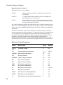
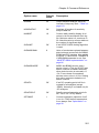
fall_delay
Fall delay
real
1nS
1e-12 - ∞
time_tol
Threshold time tolerance
real
100pS
1e-12 - ∞
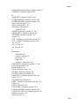
out_low
Used to calculate reflected
static load. See text
real
0
none
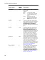
out_high
Used to calculate reflected
static load. See text
real
5
none
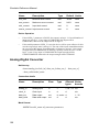
clamp_low
Clamp threshold 'ZERO'
digital input. Default to
out_low
real
out_low
none
clamp_high
Clamp threshold 'ONE' digital real
input. Default to out_high
out_high none
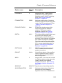
clamp_res
Clamp minimum resistance
real
1
1e-06 - ∞
clamp_bias
Clamp voltage
real
0.8
0.2 - 2
out_family
Output logic family
string
UNIV
none
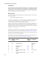
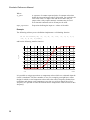
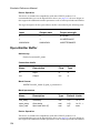
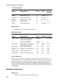
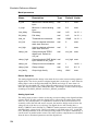
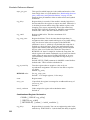
Device Operation
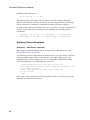
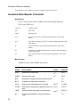
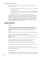
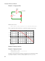
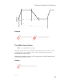
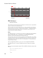
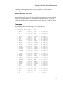
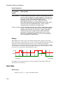
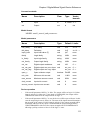
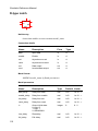
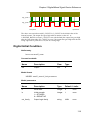
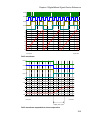
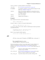
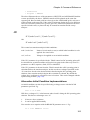
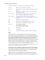
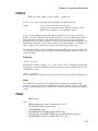
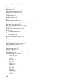
The analog-digital interface bridge is the main device used to connect analog signals to
digital inputs. The device produces a digital signal that is in the logic '1' state when the
analog input is above the high threshold (IN_HIGH) and a logic '0' state when it is
below the low threshold (IN_LOW). When the analog input is in between these two
states the output will be in the UNKNOWN state. The changes in state will be delayed
according to the RISE_DELAY and FALL_DELAY parameters.
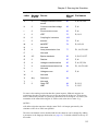
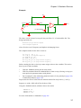
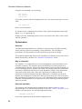
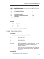
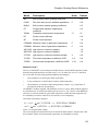
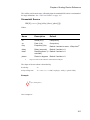
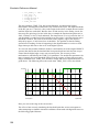
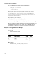
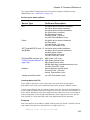
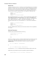
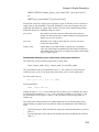
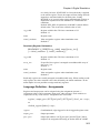
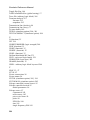
Analog input load
The analog input presents a load to its driving circuit according to the digital load that
is being driven. In other words the digital load is reflected to the analog input. Both
static (i.e. DC) and dynamic (i.e. capacitance) elements of the load are reflected. To
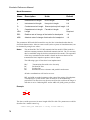
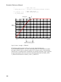
accurately reflect the sink and source currents, the interface bridge needs to know the
voltage levels of the device it is driving. The digital device will (usually) have a
SINK_CURRENT and a SOURCE_CURRENT model parameter each of which apply
at defined logic voltage levels. These levels must be specified in the OUT_LOW and
OUT_HIGH parameters of the AD interface bridge model. The input is modelled by a
current source in parallel with a resistor. The values of these components are calculated
from the above mentioned parameters and the digital load.
154